Dell Latitude E5430 Owner's Manual Regulatory Model: P27G Regulatory Type: P27G001
Notes, Cautions, and Warnings NOTE: A NOTE indicates important information that helps you make better use of your computer. CAUTION: A CAUTION indicates either potential damage to hardware or loss of data and tells you how to avoid the problem. WARNING: A WARNING indicates a potential for property damage, personal injury, or death. Copyright © 2014 Dell Inc. All rights reserved. This product is protected by U.S. and international copyright and intellectual property laws.
Contents 1 Working on Your Computer................................................................................... 7 Before Working Inside Your Computer................................................................................................ 7 Turning Off Your Computer..................................................................................................................9 After Working Inside Your Computer..................................................................................
Installing the Thermal Module............................................................................................................30 Removing the Processor.................................................................................................................... 30 Installing the Processor....................................................................................................................... 31 Removing the Palmrest..............................................................
Entering System Setup........................................................................................................................ 67 System Setup Options.........................................................................................................................67 6 Diagnostics............................................................................................................... 77 Diagnostics...................................................................................
Working on Your Computer 1 Before Working Inside Your Computer Use the following safety guidelines to help protect your computer from potential damage and to help to ensure your personal safety. Unless otherwise noted, each procedure included in this document assumes that the following conditions exist: • You have read the safety information that shipped with your computer. • A component can be replaced or--if purchased separately--installed by performing the removal procedure in reverse order.
4. Disconnect all network cables from the computer. 5. Disconnect your computer and all attached devices from their electrical outlets. 6. Close the display and turn the computer upside-down on a flat work surface. NOTE: To avoid damaging the system board, you must remove the main battery before you service the computer. 7. Remove the main battery. 8. Turn the computer top-side up. 9. Open the display. 10. Press the power button to ground the system board.
Turning Off Your Computer CAUTION: To avoid losing data, save and close all open files and exit all open programs before you turn off your computer. 1. Shut down the operating system: • In Windows 8: – Using a touch-enabled device: a. Swipe in from the right edge of the screen, opening the Charms menu and select Settings. b. Select the and then select Shut down – Using a mouse: • a. Point to upper-right corner of the screen and click Settings. b. Click the and select Shut down.
5. 10 Turn on your computer.
Removing and Installing Components 2 This section provides detailed information on how to remove or install the components from your computer. Recommended Tools The procedures in this document may require the following tools: • Small flat-blade screwdriver • #0 Phillips screwdriver • #1 Phillips screwdriver • Small plastic scribe Removing the SD Card 1. Follow the procedures in Before Working Inside Your Computer. 2. Press in on the SD card to release it from the computer. 3.
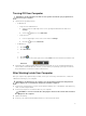
Installing the ExpressCard 1. Slide the ExpressCard in its slot until it clicks in place. 2. Follow the procedures in After Working Inside Your Computer. Removing the Battery 1. Follow the procedures in Before Working Inside Your Computer. 2. Slide the battery release latches into the unlock position. 3. Remove the battery from the computer.
Installing the Battery 1. Slide the battery into its slot until it clicks into place. 2. Follow the procedures in After Working Inside Your Computer. Removing the Access Panel 1. Follow the procedures in Before Working Inside Your Computer. 2. Remove the battery. 3. Remove the screws that secure the access panel. 4. Slide the access panel towards the front of the system and remove it from the computer.
Installing the Access Panel 1. Slide the base cover into its slot until it clicks into place. 2. Install the screws that secure the access panelto the computer. 3. Install the battery. 4. Follow the procedures in After Working Inside Your Computer. Removing the SIM Card 1. Follow the procedures in Before Working On Your Computer. 2. Remove the battery. 3. Press and release the SIM card located on the battery wall. 4. Slide the SIM card from the computer.
3. Perform the following steps: a. Pry up the bottom edge of the display bezel. b. Work your way around the sides and top edge of the display bezel. 4. Remove the display bezel from the computer. Installing the Display Bezel 1. Place the display bezel onto the display assembly. 2. Starting from the top corner, press on the display bezel and work around the entire bezel until it snaps onto the display assembly. 3. Install the battery. 4. Follow the procedures in After Working Inside Your Computer.
3. Perform the following steps: a. Remove the screw that secures the camera and microphone module. b. Disconnect the camera cable. c. Lift and remove the camera and microphone module. Installing the Camera 1. Place the camera and microphone module on its place. 2. Connect the camera cable. 3. Tighten the screw to secure the camera and microphone module. 4. Install: a. display bezel b. battery 5. Follow the procedures in After Working Inside Your Computer. Removing the Display Panel 1.
3. Remove the screws that secure the display panel. 4. Flip the display panel over.
5. Lift the mylar tape and disconnect the low-voltage differential signalling (LVDS) cable from the back of the display panel. 6. Remove the display panel from the display assembly. Installing the Display Panel 1. Place the display panel to the display assembly. 2. Align the display panel in its original position. 3. Connect the low-voltage differential signaling (LVDS) cable to the display panel and attach the tape. 4.
3. Remove the screws at the back of the computer. 4. Pry up the keyboard trim starting from the bottom edge. 5. Work your way around the sides and the top edge of the keyboard trim.
6. Lift upwards and remove the keyboard trim from the computer. Installing the Keyboard Trim 1. Align the keyboard trim to its place. 2. Press along the sides of the keyboard trim until it snaps in place. 3. Install the battery. 4. Follow the procedures in After Working Inside Your Computer.
Removing the Keyboard 1. Follow the procedures in Before Working Inside Your Computer. 2. Remove: a. battery b. keyboard trim 3. Remove the screws at the back of the computer. 4. Remove the screws that secure the keyboard in place. 5. Lift the clip to release the keyboard cable and disconnect it from the computer .
6. Flip the keyboard over. 7. Peel off the adhesive tape securing the keyboard flat flex cable to the back of the keyboard and remove it from the computer. 8. Remove the keyboard from the computer . Installing the Keyboard 1. Attach the keyboard flat flex cable to the keyboard. 2. Affix the adhesive tape securing the keyboard flat flex cable to the keyboard. 3. Slide the keyboard into its compartment until all the metal tabs fit into their positions. 4. Fasten the keyboard cable clip. 5.
7. Install the screw at the back of the computer. 8. Install: a. keyboard trim b. battery 9. Follow the procedures in After Working Inside Your Computer. Removing the Optical Drive 1. Follow the procedures in Before Working Inside Your Computer. 2. Remove: a. battery b. access panel 3. Remove the screw that secures the optical drive. 4. Push the screw tab away from the computer to release the optical drive from the drive bay.
5. Remove the optical drive from the computer. 6. Remove the screws that secure the optical drive bracket. 7. Remove the optical drive bracket. 8. Disengage the optical drive bezel tabs to separate the optical drive bezel from the optical drive. 9. Remove the optical drive bezel. Installing the Optical Drive 1. Engage the optical-drive bezel tabs to attach the optical-drive bezel to the optical drive. 2. Install the optical-drive bracket. 3.
Removing the Hard Drive 1. Follow the procedures in Before Working Inside Your Computer. 2. Remove: a. battery b. access panel 3. Remove the screws that secure the hard drive bracket in place. 4. Use the tab to pull the hard drive bracket to release the hard drive from its connector.
5. Remove the hard drive from the computer. 6. Remove the screws that secure the hard drive bracket. 7. Remove the hard drive bracket from the hard drive. Installing the Hard Drive 1. Engage the hard drive bracket to the hard drive. 2. Tighten the screws that secure the hard drive bracket. 3. Install the hard drive into the computer. 4. Tighten the screw that secures the hard drive bracket in place. 5. Install: a. access panel b. battery 6.
Removing the WLAN Card 1. Follow the procedures in Before Working Inside Your Computer. 2. Remove: a. battery b. base cover 3. Perform the following steps: a. Disconnect the antennae cables from the WLAN card. b. Remove the screw that secures the WLAN card to the computer. c. Remove the WLAN card from its slot on the system board. Installing the WLAN Card 1. Insert the WLAN card into its connector on the system board. 2.
Installing the Memory Module 1. Insert the memory into the memory socket. 2. Press the clips to secure the memory module to the system board. 3. Install: a. base cover b. battery 4. Follow the procedures in After Working Inside Your Computer. Removing the Right Base Panel 1. Follow the procedures in Before Working Inside Your Computer. 2. Remove: a. battery b. access panel 3. Remove the screws that secure the right base panel in place. 4. Remove the right base panel from the computer.
Installing the Right Base Panel 1. Place the right base panel on the computer. 2. Tighten the screws that secure right base panel to the computer. 3. Install: a. access panel b. battery 4. Follow the procedures in After Working Inside Your Computer. Removing the Thermal Module 1. Follow the procedures in Before Working Inside Your Computer. 2. Remove: a. b. c. d. 3. SD memory card battery access panel right base panel Remove the screws that secure the thermal module in place.
4. Lift up the thermal module and remove it from the computer. Installing the Thermal Module 1. Place the thermal module in its compartment. 2. Tighten the screws that secures the thermal module to the computer. 3. Install: a. b. c. d. 4. right base panel access panel battery SD memory card Follow the procedures in After Working Inside Your Computer. Removing the Processor 1. Follow the procedures in Before Working Inside Your Computer. 2. Remove: a. b. c. d. e. 3.
Installing the Processor 1. Place the processor in its socket on the computer. 2. Rotate the processor cam lock in a clockwise direction to secure the processor. 3. Install: a. b. c. d. e. 4. thermal module access panel right base panel battery SD memory card Follow the procedures in After Working Inside Your Computer. Removing the Palmrest 1. Follow the procedures in Before Working Inside Your Computer. 2. Remove: a. b. c. d. e. f. g. 3.
4. Remove the screws that secure the palmrest of the computer. 5. Disconnect the LED board flat flex cable. 6. Disconnect the media button flat flex cable. 7. Disconnect the touch pad flat flex cable. 8. Disconnect the fingerprint scanner flat flex cable. 9. Disconnect the power button flat flex cable. 10. Lift up the right edge of palmrest assembly.
11. Release the tabs on the left edge of the palm rest assembly and remove the palmrest from the computer. Installing the Palmrest 1. Align the palm rest assembly to its original position in the computer and snap it into place. 2. Connect the following cables to the system board: a. b. c. d. e. power button flat flex cable. fingerprint scanner flat flex cable touch pad flat flex cable media button flat flex cable LED board flat flex cable 3. Tighten the screws on the palmrest. 4.
Removing the ExpressCard Reader Cage 1. Follow the procedures in Before Working Inside Your Computer. 2. Remove: a. b. c. d. e. f. g. h. SD memory card battery access panel keyboard trim keyboard optical drive right base panel palmrest 3. Remove the screws that secure the ExpressCard reader cage in place. 4. Remove the ExpressCard reader cage from the computer. Installing the ExpressCard Reader Cage 1.
Removing the Bluetooth Module 1. Follow the procedures in Before Working Inside Your Computer. 2. Remove: a. b. c. d. e. f. g. h. SD memory card battery access panel keyboard trim keyboard optical drive right base panel palmrest 3. Disconnect the bluetooth cable from the system board. 4. Remove the screw that secures the bluetooth module in place. 5. Remove the bluetooth module from the computer. 6. Disconnect the bluetooth cable from the bluetooth module. Installing the Bluetooth Module 1.
Removing the Audio Board 1. Follow the procedures in Before Working Inside Your Computer. 2. Remove: a. b. c. d. e. f. g. h. i. SD memory card battery access panel keyboard trim keyboard optical drive right base panel palmrest bluetooth module 3. Disconnect the audio board flat flex cable from the system board. 4. Remove the screw that secures the audio board in place. 5. Remove the audio board from the computer. Installing the Audio Board 1. Place the audio board in the computer. 2.
Removing the Display Assembly 1. Follow the procedures in Before Working Inside Your Computer. 2. Remove: a. b. c. d. e. f. g. h. i. 3. SD memory card battery access panel keyboard trim keyboard optical drive hard drive right base panel palmrest Disconnect and remove any antennae from the routing channels.
4. Disconnect the low-voltage differential signaling (LVDS) cable. 5. Pull the antennas through the opening to the top of the computer.
6. Remove the screws that secure the display assembly in place. 7. Remove the display assembly from the computer. Installing the Display Assembly 1. Install the screws that secures the display assembly in place. 2. Insert the low-voltage differential signaling (LVDS) cable and wireless antennae cables through the holes on the chassis. 3. Route the LVDS cable along its compartment and connect the connector to the system board. 4. Connect the antenna cables to their connectors. 5. Install: a. b.
Removing the Right Support Frame 1. Follow the procedures in Before Working Inside Your Computer. 2. Remove: a. b. c. d. e. f. g. h. i. j. k. l. m. SD memory card ExpressCard battery access panel keyboard trim keyboard optical drive hard drive WLAN card right base panel thermal module palmrest display assembly 3. Disconnect the flat flex cable located at the base of the right support frame. 4. Remove the screws that secure the right support frame to the computer.
5. Lift the right support frame away from the computer. Installing the Right Support Frame 1. Place the right support frame on the computer. 2. Tighten the screws to secure the right support frame to the computer. 3. Connect the flat flex cable located at the base of the right support frame. 4. Install: a. b. c. d. e. f. g. h. i. j. k. l. m. 5.
Removing the Modem Card 1. Follow the procedures in Before Working Inside Your Computer. 2. Remove: a. b. c. d. e. f. g. h. i. j. k. l. m. n. SD memory card ExpressCard battery access panel keyboard trim keyboard optical drive hard drive right base panel thermal module palmrest ExpressCard reader cage display assembly right support frame 3. Remove the screw that secures the modem card to the computer. 4. Lift the modem card to disengage it from the connector on the back of the card. 5.
5. Install: a. b. c. d. e. f. g. h. i. j. k. l. m. n. 6. right support frame display assembly ExpressCard reader cage palmrest thermal module right base panel hard drive optical drive keyboard keyboard trim access panel battery ExpressCard SD memory card Follow the procedures in After Working Inside Your Computer. Removing the Left Support Frame 1. Follow the procedures in Before Working Inside Your Computer. 2. Remove: a. b. c. d. e. f. g. h. i. j. k. l. m. 3.
4. Lift the left support frame away from the computer. Installing the Left Support Frame 1. Place the left support frame on the computer. 2. Tighten the screws to secure the left support frame to the computer. 3. Install: a. b. c. d. e. f. g. h. i. j. k. l. m. 4. 44 display assembly palmrest thermal module right base panel WLAN card hard drive optical drive keyboard keyboard trim access panel battery ExpressCard SD memory card Follow the procedures in After Working Inside Your Computer.
Removing the System Board 1. Follow the procedures in Before Working Inside Your Computer. 2. Remove: a. b. c. d. e. f. g. h. i. j. k. l. m. battery access panel keyboard trim keyboard optical drive hard drive WLAN card right base panel thermal module palmrest ExpressCard reader cage display assembly left support frame 3. Disconnect the power connector cable. 4. Disconnect the system fan cable from the system board. 5. Disconnect the speaker cable from the system board. 6.
7. Disconnect the bluetooth cable. 8. Remove the screws that secure the system board.
9. Lift the right edge of the system board assembly and raise it to a 45–degree angle. 10. Release the system board from the port connectors on the left and remove the system board. Installing the System Board 1. Align the system board into its original position on the computer. 2. Replace and tighten the screws to secure the system board to the computer. 3. Route and connect the following cables the system board: a. b. c. d. e.
4. Install: a. b. c. d. e. f. g. h. i. j. k. l. m. 5. left support frame display assembly ExpressCard reader cage palmrest thermal module right base panel hard drive optical drive keyboard keyboard trim access panel battery SD memory card Follow the procedures in After Working Inside Your Computer. Removing the Coin-Cell Battery 1. Follow the procedures in Before Working Inside Your Computer. 2. Remove: a. b. c. d. e. f. g. h. i. j. k. l. m. n. o.
Installing the Coin-Cell Battery 1. Place the coin-cell battery on the system board with adhesive side downwards. 2. Connect the coin-cell battery cable to the system board. 3. Install: a. b. c. d. e. f. g. h. i. j. k. l. m. n. o. p. 4.
4. Lift the Input/Output (IO) board out of the computer. Installing the Input/Output (I/O) Board 1. Place the Input/Output (I/O) board in the computer. 2. Tighten the screw to secure the Input/Output (I/O) board to the computer. 3. Install: a. b. c. d. e. f. g. h. i. j. k. l. m. n. o. p. q. 4.
Removing the Power Connector 1. Follow the procedures in Before Working Inside Your Computer. 2. Remove: a. b. c. d. e. f. g. h. i. j. k. l. m. n. o. p. 3. SD memory card ExpressCard battery access panel keyboard trim keyboard optical drive hard drive WLAN card right base panel thermal module palmrest ExpressCard reader cage display assembly left support bracket system board Remove the power connector cable from the routing channels.
4. Remove the power connector. Installing the Power Connector 1. Install the power connector in the computer. 2. Thread the power connector in the routing channel. 3. Install: a. b. c. d. e. f. g. h. i. j. k. l. m. n. o. p. 4.
Removing the System Fan 1. Follow the procedures in Before Working Inside Your Computer. 2. Remove: a. b. c. d. e. f. g. h. i. j. k. l. m. n. o. p. q. r. s. t. 3.
4. Lift the system fan out of the computer. Installing the System Fan 1. Place the system fan in the computer. 2. Tighten the screws to secure the fan in the computer. 3. Install: a. b. c. d. e. f. g. h. i. j. k. l. m. n. o. p. q. r. s. t. 4.
Removing the Network Connector 1. Follow the procedures in Before Working Inside Your Computer. 2. Remove: a. b. c. d. e. f. g. h. i. j. k. l. m. n. o. p. q. r. SD memory card ExpressCard battery access panel keyboard trim keyboard optical drive hard drive WLAN card right base panel thermal module palmrest ExpressCard reader cage display assembly right support frame left support frame modem card system board 3. Remove the network connector cables from the routing channels. 4.
3. Install: a. b. c. d. e. f. g. h. i. j. k. l. m. n. o. p. q. r. 4. system board modem card left support frame right support frame display assembly ExpressCard reader cage palmrest thermal module right base panel WLAN card hard drive optical drive keyboard keyboard trim access panel battery ExpressCard SD memory card Follow the procedures in After Working Inside Your Computer. Removing the Speakers 1. Follow the procedures in Before Working Inside Your Computer. 2. Remove: a. b. c. d. e. f. g. h.
3. Remove the screws to release the speakers. 4. Remove the speaker cables from the routing channels. 5. Lift the speaker out from the computer. Installing the Speakers 1. Place the speakers in the computer. 2. Tighten the screws to secure the speakers to the computer. 3. Connect the speaker cables and secure it in the routing channels.
4. Install: a. b. c. d. e. f. g. h. i. j. k. l. m. n. o. p. q. r. 5. 58 system board left support frame display assembly audio board bluetooth module ExpressCard reader cage palmrest thermal module right base panel WLAN card hard drive optical drive keyboard keyboard trim access panel battery ExpressCard SD memory card Follow the procedures in After Working Inside Your Computer.
3 Specifications Specifications NOTE: Offerings may vary by region. For more information regarding the configuration of your computer, click Start (Start icon) → Help and Support, and then select the option to view information about your computer. Table 1. System Information Feature Specification Chipset Intel HM77/QM77 Express Chipset DRAM bus width 64-bit Flash EPROM SPI 32 Mbits PCIe Gen1 bus 100 MHz External Bus Frequency DMI (5GT/s) Table 2.
Table 4. Audio Feature Specification Type four-channel high definition audio Controller IDT92HD93 Stereo conversion 24-bit (analog-to-digital and digital-to-analog) Interface: Internal high definition audio External microphone-in/stereo headphones/external speakers connector Speakers two Internal speaker amplifier 1W (RMS) per channel Volume controls keyboard function keys, program menus Table 5.
Feature Specification Subscriber Identity Module (SIM) port one Table 8. Display Feature Specification Type Latitude E5430 • • HD(1366x768), WLED HD+(1600 x 900) Latitude E5530 • • HD(1366x768), WLED FHD (1920 x 1080) Latitude E5430 14.0" Latitude E5530 15.6" Size Dimensions: Latitude E5430: Height 192.5 mm (7.57 inches) Width 324 mm (12.75 inches) Diagonal 355.60 mm (14.00 inches) Active ares (X/Y) 309.40 mm x 173.
Feature Vertical Specification • +/- 60° for FHD • • +10°/-30° for HD +/-50° for FHD Pixel pitch: Latitude E5430 0.2265 mm x 0.2265 mm Latitude E5530 • • 0.2520 mm x 0.2520 mm for HD 0.1790 x 0.1790 for FHD Table 9. Keyboard Feature Specifcation Number of keys United States: 86 keys, United Kingdom: 87 keys, Brazil: 87 keys, and Japan: 90 keys Layout QWERTY/AZERTY/Kanji Table 10. Touchpad Feature Specification Active Area: X-axis 80.00 mm Y-axis 45.00 mm Table 11.
Feature Specification 6-cell 344.73 g (0.76 lb) 9-cell 508.20 g (1.12 lb) Voltage 4-cell 14.8 VDC 6- and 9-cell 11.1 VDC Temperature range: Operating 0 °C to 50 °C (32 °F to 122 °F) Non-Operating –40 °C to 85 °C (–40 °F to 185 °F) NOTE: The battery pack is capable of safely withstanding the above storage temperatures with 100% charge. NOTE: The battery pack is also capable of withstanding storage temperatures from –20 °C to +60 °C with no degradation in its performance.
Physical Weight Latitude E5430 Latitude E5530 2.04 kg (4.50 lb) 2.38 kg (5.25 lb) Table 14. Environmental Feature Specification Temperature: Operating 0 °C to 35 °C (32 °F to 95 °F) Storage –40 °C to 65 °C (–40 °F to 149 °F) Relative humidity (maximum): Operating 10 % to 90 % (non condensing) Storage 5 % to 95 % (non condensing) Altitude (maximum): Operating –15.24 m to 3048 m (–50 ft to 10,000 ft) Non-Operating –15.
4 Additional Information This section provides information for the additional features that are part of your computer. Docking Port Information The docking port is used for connecting the laptop to a docking station (optional). 1. Subscriber Identity Module (SIM) Port 2.
5 System Setup Overview System Setup allows you to: • change the system configuration information after you add, change, or remove any hardware in your computer. • set or change a user-selectable option such as the user password. • read the current amount of memory or set the type of hard drive installed. CAUTION: Unless you are an expert computer user, do not change the settings for this program. Certain changes can cause your computer to work incorrectly. Entering System Setup 1.
Option Description • Maximum Clock Speed, Processor L2 Cache, Processor L3 Cache, HT Capable, and 64-Bit Technology. Device Information: Displays Primary Hard Drive, Fixed bay Device, System eSATA Device, Dock eSATA Device, LOM MAC Address, Video Controller, Video BIOS Version, Video Memory, Panel Type, Native Resolution, Audio Controller, Modem Controller, Wi-Fi Device, Cellular Device, Bluetooth Device.
Option Description Serial Port Allows you to configure the integrated serial port. The options are: • • • • • SATA Operation Allows you to configure the internal SATA hard-drive controller. The options are: • • • • Drives SATA-0 SATA-1 SATA-4 SATA-5 This field controls whether hard drive errors for integrated drives are reported during system startup. This technology is part of the SMART (Self Monitoring Analysis and Reporting Technology) specification. This option is disabled by default.
Option Description • • Miscellaneous Devices Level is 75% Level is 100% Allows you to enable or disable the following devices: • • • • • • • Enable Internal Modem Enable Microphone Enable eSATA Ports Enable Hard Drive Free Fall Protection Enable Fixed Bay Enable Express card Enable Camera NOTE: All devices are enabled by default. You can also enable or disable Media Card. Table 17.
Option Description Default Setting: Enable Strong Password is not selected. NOTE: If Strong Password is enabled, Admin and System passwords must contain at least one uppercase character, one lowercase character and be at least 8 characters long. Password Configuration Allows you to determine the minimum and maximum length of Administrator and System passwords. Password Bypass Allows you to enable or disable the permission to bypass the System and the Internal HDD password, when they are set.
Option Description Admin Setup Lockout Allows you to prevent users from entering Setup when an Administrator password is set. Default Setting: Enable Admin Setup Lockout is not selected. Table 19. Performance Option Description Multi Core Support This field specifies whether the process will have one or all cores enabled. The performance of some applications will improve with the additional cores. This option is enabled by default.Allows you to enable or disable multi-core support for the processor.
Option Description USB Wake Support Allows you to enable USB devices to wake the system from Standby. NOTE: This feature is only functional when the AC power adapter is connected. If the AC power adapter is removed during Standby, the system setup will remove power from all of the USB ports to conserve battery power. • • Wireless Radio Control Allows you to enable or disable the feature that automatically switches from wired or wireless networks without depending on the physical connection.
Table 21. POST Behavior Option Description Adapter Warnings Allows you to enable or disable the system setup (BIOS) warning messages when you use certain power adapters. Default Setting: Enable Adapter Warnings Keypad Allows you to choose one of two methods to enable the keypad that is embedded in the internal keyboard. • • Mouse/Touchpad Allows you to define how the system handles mouse and touch pad input. The options are: • • • Numlock Enable Fn Key Only: This option is enabled by default.
Table 23. Wireless Option Description Wireless Switch Allows to set the wireless devices that can be controlled by the wireless switch. The options are: • • • WWAN WLAN Bluetooth All the options are enabled by default. Wireless Device Enable Allows you to enable or disable the internal wireless devices. • • • WWAN WLAN Bluetooth All the options are enabled by default. Table 24. Maintenance Option Description Service Tag Displays the Service Tag of your computer.
6 Diagnostics If you experience a problem with your computer, run the ePSA diagnostics before contacting Dell for technical assistance. The purpose of running diagnostics is to test your computer's hardware without requiring additional equipment or risking data loss. If you are unable to fix the problem yourself, service and support personnel can use the diagnostics results to help you solve the problem. Diagnostics Table 26.
Table 28. Keyboard Status Lights Turns on when the numeric keypad is enabled. Turns on when the Caps Lock function is enabled. Turns on when the Scroll Lock function is enabled.
Contacting Dell 7 NOTE: If you do not have an active Internet connection, you can find contact information on your purchase invoice, packing slip, bill, or Dell product catalog. Dell provides several online and telephone-based support and service options. Availability varies by country and product, and some services may not be available in your area. To contact Dell for sales, technical support, or customer service issues: 1. Visit dell.com/support 2. Select your support category. 3.