Dell Latitude E6440 Benutzerhandbuch Vorschriftenmodell: P38G Vorschriftentyp: P38G001
Anmerkungen, Vorsichtshinweise und Warnungen ANMERKUNG: Eine ANMERKUNG liefert wichtige Informationen, mit denen Sie den Computer besser einsetzen können. VORSICHT: Ein VORSICHTSHINWEIS macht darauf aufmerksam, dass bei Nichtbefolgung von Anweisungen eine Beschädigung der Hardware oder ein Verlust von Daten droht, und zeigt auf, wie derartige Probleme vermieden werden können.
Inhaltsverzeichnis 1 Arbeiten am Computer............................................................................................................... 6 Vor der Arbeit an Komponenten im Innern des Computers......................................................................................6 Ausschalten des Computers.....................................................................................................................................7 Nach der Arbeit an Komponenten im Innern des Computers..
Einbauen des Prozessors....................................................................................................................................... 24 Entfernen des Stromanschlusses...........................................................................................................................24 Installieren des Stromanschlusses........................................................................................................................
Technische Daten..................................................................................................................... 62 6 Kontaktaufnahme mit Dell........................................................................................................
Arbeiten am Computer 1 Vor der Arbeit an Komponenten im Innern des Computers Die folgenden Sicherheitshinweise schützen den Computer vor möglichen Schäden und dienen der persönlichen Sicherheit des Benutzers. Wenn nicht anders angegeben, ist bei jedem in diesem Dokument beschriebenen Vorgang darauf zu achten, dass die folgenden Bedingungen erfüllt sind: • Sie haben die Arbeitsschritte unter „Arbeiten am Computer“ durchgeführt.
3. Falls der Computer mit einer Dockingstation verbunden (angedockt) ist, etwa der optionalen Media-Base oder dem Slice-Akku, trennen Sie die Verbindung. VORSICHT: Wenn Sie ein Netzwerkkabel trennen, ziehen Sie es zuerst am Computer und dann am Netzwerkgerät ab. 4. Trennen Sie alle Netzwerkkabel vom Computer. 5. Trennen Sie den Computer sowie alle daran angeschlossenen Geräte vom Stromnetz. 6.
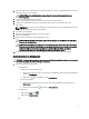
2. 1. Klicken Sie auf Start (Start) , 2. Klicken Sie auf den Pfeil unten rechts im Startmenü (siehe Abbildung unten), und klicken Sie anschließend auf Herunterfahren. Stellen Sie sicher, dass der Computer und alle angeschlossenen Geräte ausgeschaltet sind. Wenn der Computer und die angeschlossenen Geräte nicht automatisch beim Herunterfahren des Betriebssystems ausgeschaltet wurden, halten Sie den Betriebsschalter 4 Sekunden lang gedrückt.
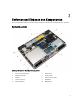
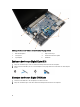
Entfernen und Einbauen von Komponenten 2 Dieser Abschnitt bietet detaillierte Informationen über das Entfernen und Einbauen von Komponenten Ihres Computers. Systemübersicht Abbildung 1. Rückansicht – Rückseitige Abdeckung entfernt 1. Gehäuseeckenabdeckungen 2. Netzanschluss 3. Kühlkörperbaugruppe 4. Speichermodul 5. SD-Karte 6. ExpressCard-Steckplatz 7. Optisches Laufwerk 8. WLAN-Karte 9. Knopfzellenbatterie 10.
Abbildung 2. Ansicht von oben – Tastatur- und Handballenstütze-Baugruppe entfernt 1. WiFi-Schalterplatine 2. ExpressCard-Träger 3. Lautsprecher 4. Laufwerkschacht für Festplatte 5. Systemplatine 6. E/A-Platine Entfernen der Secure-Digital-Karte (SD) 1. Folgen Sie den Anweisungen unter Vor der Arbeit an Komponenten im Innern des Computers. 2. Drücken Sie auf die SD-Karte, bis sie aus dem Computer herausspringt. Ziehen Sie die SD-Karte aus dem Computer heraus.
Entfernen der ExpressCard 1. Folgen Sie den Anweisungen unter Vor der Arbeit an Komponenten im Innern des Computers. 2. Drücken Sie auf die ExpressCard-Karte, um sie aus dem Computer zu lösen. Schieben Sie die ExpressCard-Karte aus dem Computer. Einsetzen der ExpressCard 1. Schieben Sie die ExpressCard in den entsprechenden Steckplatz, bis sie hörbar einrastet. 2. Folgen Sie den Anweisungen unter Nach der Arbeit an Komponenten im Inneren des Computers. Entfernen des Akkus 1.
Entfernen der Bodenabdeckung 1. Folgen Sie den Anweisungen unter Vor der Arbeit an Komponenten im Innern des Computers. 2. Entfernen Sie die Schrauben, mit denen die Abdeckung am Computer befestigt ist und heben Sie die hintere Bodenabdeckung ab, um sie vom Computer zu entfernen. Einsetzen der Abdeckung an der Unterseite 1. Setzen Sie die Abdeckung an der Unterseite passend zu den Schraublöchern auf den Computer. 2.
Einbauen des Speichers 1. Setzen Sie den Speicher in den Speichersockel ein. 2. Drücken Sie auf die Halteklammern, um das Speichermodul auf der Systemplatine zu verankern. 3. Einbau von: a. Hintere Bodenabdeckung b. Akku 4. Folgen Sie den Anweisungen unter Nach der Arbeit an Komponenten im Inneren des Computers. Entfernen des Festplattenlaufwerks 1. Folgen Sie den Anweisungen unter Vor der Arbeit an Komponenten im Innern des Computers. 2. Entfernen Sie den Akku. 3.
Einsetzen des Festplattenlaufwerks 1. Bringen Sie die Festplattenisolierung am Festplattenlaufwerk an. 2. Befestigen Sie die Festplattenlaufwerkhalterung am Festplattenlaufwerk. 3. Ziehen Sie die Schrauben fest, um die Festplattenlaufwerkhalterung am Festplattenlaufwerk zu befestigen. 4. Schieben Sie das Festplattenlaufwerk in den Computer. 5. Ziehen Sie die Schrauben fest, um das Festplattenlaufwerk am Computer zu befestigen. 6. Setzen Sie den Akku ein. 7.
5. Entfernen Sie die Schrauben, mit denen die Halterung der Verriegelung des optischen Laufwerks am optischen Laufwerk befestigt ist. Entfernen Sie die Halterung der Verriegelung vom optischen Laufwerk. Einsetzen des optischen Laufwerks 1. Richten Sie die Halterung der Verriegelung des optischen Laufwerks an seiner Position auf dem optischen Laufwerk aus. 2. Ziehen Sie die Schraube fest, um die Haltung der Verriegelung des optischen Laufwerks am optischen Laufwerk zu befestigen. 3.
3. Führen Sie einen Plastikstift unter dem Tastaturrahmen entlang, um ihn vom Computer zu lösen. Heben Sie den Tastaturrahmen vom Computer ab und entfernen Sie ihn. Einsetzen des Tastaturrahmens 1. Richten Sie den Tastaturrahmen an seinem Fach aus. 2. Drücken Sie die Seiten des Tastaturrahmens nach unten, bis er einrastet. 3. Setzen Sie den Akku ein. 4. Folgen Sie den Anweisungen unter Nach der Arbeit an Komponenten im Inneren des Computers. Entfernen der Tastatur 1.
4. Entfernen Sie die Schrauben, mit denen die Tastatur an der Handballenstützen-Baugruppe befestigt ist. Heben Sie die Tastatur an und drehen Sie sie herum, um auf das Tastaturkabel zugreifen zu können. 5. Trennen Sie das Tastaturkabel von der Systemplatine.
Einsetzen der Tastatur 1. Schließen Sie das Tastaturkabel an die Systemplatine an. 2. Schieben Sie die Tastatur in ihr Fach, bis sie einrastet. 3. Bringen Sie die die Schrauben wieder an und ziehen Sie sie fest, mit denen die Tastatur an der HandballenstützenBaugruppe befestigt wird. 4. Drehen Sie den Computer um und ziehen Sie die Schrauben auf der Rückseite des Computers fest. 5. Bauen Sie den Tastaturrahmen ein. 6. Setzen Sie den Akku ein. 7.
Einbauen der WLAN-Karte 1. Setzen Sie die WLAN-Karte in einem 45-Grad-Winkel in ihren Steckplatz ein. 2. Schließen Sie die Antennenkabel an ihren entsprechend gekennzeichneten Anschlüssen auf der WLAN-Karte an. 3. Ziehen Sie die Schraube fest, um die WLAN-Karte am Computer zu befestigen. 4. Einbau von: a. Hintere Bodenabdeckung b. Akku 5. Folgen Sie den Anweisungen unter Nach der Arbeit an Komponenten im Inneren des Computers. Entfernen der WWAN-Karte 1.
4. Einbau von: a. Hintere Bodenabdeckung b. Akku 5. Folgen Sie den Anweisungen unter Nach der Arbeit an Komponenten im Inneren des Computers. Entfernen der Gehäuseeckenabdeckung 1. 2. Folgen Sie den Anweisungen unter Vor der Arbeit an Komponenten im Innern des Computers. Entfernen Sie folgende Komponenten: a. Akku b. Bodenabdeckung c. Festplattenlaufwerk 3.
4. Folgen Sie den Anweisungen unter Nach der Arbeit an Komponenten im Inneren des Computers. Entfernen des Netzwerkanschlusses 1. Folgen Sie den Anweisungen unter Vor der Arbeit an Komponenten im Innern des Computers. 2. Entfernen Sie: a. Akku b. Bodenabdeckung c. Gehäuseeckenabdeckung (links) 3. Führen Sie folgende Schritte wie in der Abbildung gezeigt durch: a. Trennen Sie das Kabel von der Systemplatine [1]. b. Lösen Sie die Kabel aus der Kabelführung [2]. c.
Entfernen der Knopfzellenbatterie 1. Folgen Sie den Anweisungen unter Vor der Arbeit an Komponenten im Innern des Computers. 2. Entfernen Sie: a. Akku b. Hintere Bodenabdeckung 3. Trennen Sie das Kabel des Knopfzellenakkus. Hebeln Sie den Knopfzellenakku nach oben und entfernen Sie ihn aus dem Computer. Einsetzen der Knopfzellenbatterie 1. Setzen Sie die Knopfzellenbatterie in ihren Steckplatz. 2. Schließen Sie das Knopfzellenbatteriekabel auf der Systemplatine an. 3. Einbau von: a.
4. Führen Sie folgende Schritte wie in der Abbildung gezeigt durch: a. Heben Sie die Kühlkörperbaugruppe aus dem Computer. b. Schieben Sie die Kühlkörperbaugruppe. Einbauen der Kühlkörperbaugruppe 1. Platzieren Sie den Kühlkörper an seiner ursprüngliche Position auf der Systemplatine. 2. Ziehen Sie die Schrauben fest, um die Kühlkörperbaugruppe auf der Systemplatine zu befestigen. 3. Schließen Sie das Lüfterkabel an die Systemplatine an. 4. Bauen Sie folgende Komponenten ein: a. Bodenabdeckung b.
Entfernen des Prozessors 1. Folgen Sie den Anweisungen unter Vor der Arbeit an Komponenten im Innern des Computers. 2. Entfernen Sie: a. Akku b. Bodenabdeckung c. Kühlkörperbaugruppe 3. Drehen Sie den Verriegelungsnocken des Prozessors entgegen dem Uhrzeigersinn. Entfernen Sie den Prozessor aus dem Computer. Einbauen des Prozessors 1. Richten Sie die Kerben am Prozessor und am Sockel aneinander aus und setzen Sie den Prozessor in den Sockel ein. 2.
4. Lösen Sie das Kamerakabel und die LVDS-Kabel, die den Stromversorgungsanschluss am Computer befestigen, aus der Führung. 5. Trennen Sie das Stromversorgungskabel und entfernen Sie die Schraube, mit der der Stromversorgungsanschluss am Computer befestigt ist.
Installieren des Stromanschlusses 1. Bringen Sie den Stromversorgungsanschluss in seinem Steckplatz an. 2. Schließen Sie das Stromversorgungskabel an und ziehen Sie die Schraube an, mit der der Stromversorgungsanschluss am Computer befestigt ist. 3. Platzieren Sie das Kamerakabel und das LVDS-Kabel, das den Stromversorgungsanschluss am Computer befestigt, in der Führung. 4.
Entfernen der Handballenstützen-Baugruppe 1. Folgen Sie den Anweisungen unter Vor der Arbeit an Komponenten im Innern des Computers. 2. Entfernen Sie: a. b. c. d. e. f. g. h. i. j. SD-Karte ExpressCard Akku Tastaturrahmen Tastatur Festplattenlaufwerk Optisches Laufwerk Bildschirmscharnierabdeckung Bodenabdeckung Gehäuseeckenabdeckungen 3. Entfernen Sie die Schrauben, mit denen die Handballenstütze an der Unterseite des Computers befestigt ist. 4.
5. Entfernen Sie die Schrauben, mit denen die Handballenstützen-Baugruppe am Computer befestigt ist. Einbauen der Handballenstützen-Baugruppe 1. Bringen Sie die Handballenstützen-Baugruppe in ihre ursprüngliche Position im Computer und lassen Sie sie einrasten. 2. Ziehen Sie die Schrauben fest, um die Handballenstützen-Baugruppe am Computer zu befestigen. 3. Verbinden Sie die folgenden Kabel: a. b. c. d. e.
4. Drehen Sie den Computer um und ziehen Sie die Schrauben fest, um die Handballenstützen-Baugruppe am Computersockel zu befestigen. 5. Bauen Sie folgende Komponenten ein: a. b. c. d. e. f. g. h. i. j. 6. Gehäuseeckenabdeckungen Bodenabdeckung Bildschirmscharnierabdeckung Optisches Laufwerk Festplattenlaufwerk Tastatur Tastaturrahmen Akku ExpressCard SD-Karte Folgen Sie den Anweisungen unter Nach der Arbeit an Komponenten im Inneren des Computers. Entfernen des ExpressCard-Kartenträgers 1.
Einbauen des ExpressCard-Kartenträgers 1. Bringen Sie die ExpressCard-Kartenträger an seinem Steckplatz an. 2. Ziehen Sie die Schrauben fest, um den ExpressCard-Träger auf der Systemplatine zu befestigen. 3. Ziehen Sie die Schraube fest, um die Abdeckung des ExpressCard-Trägers am Computer zu befestigen. 4. Bauen Sie folgende Komponenten ein: a. b. c. d. e. f. g. h. i. j. k. 5.
3. Führen Sie folgende Schritte wie in der Abbildung gezeigt durch: a. Ziehen Sie das Kabel der WiFi-Schalterplatine von der Systemplatine ab. b. Entfernen Sie die Schrauben, mit der die WiFi-Schalterplatine befestigt ist, und heben Sie sie aus dem Computer. Installieren der WiFi-Schalterplatine 1. Setzen Sie die WiFi-Schalterplatine in ihren Steckplatz ein. 2. Ziehen Sie die Schrauben fest, um die WiFi-Schalterplatine am Computer zu befestigen. 3.
f. g. h. i. j. k. l. m. n. o. p. q. r. s. Festplattenlaufwerk Optisches Laufwerk Bildschirmscharnierabdeckung Bodenabdeckung Gehäuseeckenabdeckungen Netzanschluss Knopfzellenbatterie Speicher WLAN-Karte WWAN-Karte Kühlkörperbaugruppe Prozessor Handballenstützen-Baugruppe ExpressCard-Träger 3. Entfernen Sie das Kabel der Knopfzellenbatterie und die Lautsprecherkabel und entfernen Sie sie von der Systemplatine. 4. Entfernen Sie die Schrauben, mit denen die Systemplatine am Computer befestigt ist.
5. Heben Sie die Systemplatine vom Computer ab. Einbauen der Systemplatine 1. Setzen Sie die Systemplatine passend zu den Ports auf den Computer ein. 2. Verbinden Sie das Kabel der WiFi-Schalterplatine mit der Systemplatine und ziehen Sie die Schrauben fest, um die Systemplatine zu befestigen. 3. Verbinden Sie folgende Kabel mit der Systemplatine: a. Lautsprecher b. Knopfzellenbatterie 4. Bauen Sie folgende Komponenten ein: a. b. c. d. e. f. g.
h. i. j. k. l. m. n. o. p. q. r. s. 5. Knopfzellenbatterie Netzanschluss Gehäuseeckenabdeckungen Bodenabdeckung Bildschirmscharnierabdeckung Optisches Laufwerk Festplattenlaufwerk Tastaturrahmen Tastatur Akku ExpressCard SD-Karte Folgen Sie den Anweisungen unter Nach der Arbeit an Komponenten im Inneren des Computers. Entfernen der Lautsprecher 1. Folgen Sie den Anweisungen unter Vor der Arbeit an Komponenten im Innern des Computers. 2. Entfernen Sie: a. b. c. d. e. f. g. h. i. j. k. l. m. n. o. p. q.
Einbauen der Lautsprecher 1. Richten Sie den Lautsprecher in der richtigen Position auf dem Computer aus und führen Sie die Lautsprecherkabel durch die Kabelführungskanäle auf dem Computer. 2. Ziehen Sie die Schrauben fest, um die Lautsprecher zu befestigen. 3. Bauen Sie folgende Komponenten ein: a. b. c. d. e. f. g. h. i. j. k. l. m. n. o. p. q. r. s. t. 4.
d. e. f. g. h. i. j. k. l. m. n. o. p. q. 3. Tastaturrahmen Tastatur Festplattenlaufwerk Optisches Laufwerk Bildschirmscharnierabdeckung Bodenabdeckung Speicher WLAN-Karte WWAN-Karte Gehäuseeckenabdeckungen Handballenstütze Lautsprecher Bildschirmbaugruppe Systemplatine Trennen Sie das E/A-Kabel von der Systemplatine und entfernen Sie die Schrauben, mit der die E/A-Platine am Computer befestigt ist. Entfernen Sie die E/A-Platine aus dem Computer. Einsetzen der E/A-Platine 1.
m. n. o. p. q. 5. Tastaturrahmen Festplattenlaufwerk Akku Express Kartenträger SD-Karte Folgen Sie den Anweisungen unter Nach der Arbeit an Komponenten im Inneren des Computers. Entfernen der Bildschirmbaugruppe 1. Folgen Sie den Anweisungen unter Vor der Arbeit an Komponenten im Innern des Computers. 2. Entfernen Sie: a. b. c. d. e. f. g. h. i. j.
5. Entfernen Sie die Bildschirmbaugruppe vom Computer. Einsetzen der Bildschirmbaugruppe 1. Platzieren Sie die Bildschirmbaugruppe an ihrer Position auf dem Computer. 2. Ziehen Sie das LVDS-Kabel und das Kamerakabel durch den Führungskanal. Ziehen Sie die Schrauben fest, um die Bildschirmbaugruppe zu befestigen. 3. Schließen Sie die Wireless-Antennen entlang ihrer Kanäle an und schließen Sie sie wieder an die entsprechenden Wireless-Module an. 4. Bauen Sie folgende Komponenten ein: a. b. c. d. e.
g. h. i. j. 5. Festplattenlaufwerk Tastatur Tastaturrahmen Akku Folgen Sie den Anweisungen unter Nach der Arbeit an Komponenten im Inneren des Computers. Entfernen der Bildschirmblende 1. Folgen Sie den Anweisungen unter Vor der Arbeit an Komponenten im Innern des Computers. 2. Entfernen Sie: a. b. c. d. e. Akku Bildschirmscharnierabdeckung Hintere Bodenabdeckung Gehäuseeckenabdeckungen Bildschirmbaugruppe 3. Heben Sie die Bildschirmblende entlang der Kanten an, um sie zu lösen. 4.
Einsetzen der Bildschirmblende 1. Bringen Sie die Blende an der Bildschirmbaugruppe an. 2. Drücken Sie die Bildschirmblende von der Oberseite beginnend nach unten und arbeiten Sie sich entlang der gesamten Blende vor, bis diese in die Bildschirmbaugruppe einrastet. 3. Drücken Sie auf die linken und rechten Kanten der Bildschirmblende. 4. Einbau von: a. b. c. d. e. 5.
3. Entfernen Sie die Schrauben, mit denen der Bildschirm an der Bildschirmbaugruppe befestigt ist. 4. Drehen Sie den Bildschirm um.
5. Ziehen Sie das Klebeband des LVDS-Kabelanschluss ab und trennen Sie das LVDS-Kabel vom Bildschirm. Entfernen Sie den Bildschirm von der Bildschirmbaugruppe. Einsetzen des Bildschirms 1. Schließen Sie das LVDS-Kabel an und bringen Sie das Klebeband am LVDS-Kabelanschluss an. 2. Drehen Sie den Bildschirm um und platzieren Sie ihn in der Bildschirmbaugruppe. 3. Ziehen Sie die Schrauben fest, um den Bildschirm an der Bildschirmbaugruppe zu befestigen. 4. Einbau von: a. b. c. d. e. f. 5.
e. Bildschirmbaugruppe f. Bildschirmblende g. Bildschirm 3. Führen Sie die folgenden Schritte aus, wie in der Abbildung dargestellt: a. Entfernen Sie die Schrauben, mit denen die Bildschirmscharniere am Bildschirm befestigt sind. b. Entfernen Sie die Bildschirmscharniere vom Computer. Einbauen der Bildschirmsscharniere 1. Bringen Sie die Bildschirmscharniere in ihrer Position auf dem Computer an. 2.
Einbauen der Kamera 1. Platzieren Sie das Kameramodul im entsprechenden Steckplatz im Computer. 2. Ziehen Sie die Schraube fest, mit der die Kamera an der Bildschirmbaugruppe befestigt ist. 3. Schließen Sie das Kamerakabel an. 4. Einbau von: a. Bildschirmblende b. Bildschirmbaugruppe c. Akku 5. 44 Folgen Sie den Anweisungen unter Nach der Arbeit an Komponenten im Inneren des Computers.
System-Setup 3 Über das System-Setup können Sie die Verwaltung der Computerhardware und die Festlegung der BIOS-Level-Optionen verwalten.
Tabelle 1. Navigationstasten Tasten Navigation Pfeil nach oben Zurück zum vorherigen Feld Pfeil nach unten Vorwärts zum nächsten Feld Ermöglicht die Eingabe eines Wertes im ausgewählten Feld (falls zutreffend) oder das Verfolgen des Links in dem Feld. Leertaste Öffnet oder schließt gegebenenfalls eine Dropdown-Liste. Weiter zum nächsten Fokusbereich.
Option Beschreibung • Aktuelle Taktrate, Minimale Taktrate, Maximale Taktrate, Prozessor-L2-Cache, Prozessor-L3-Cache, HT-Fähigkeit und 64Bit-Technologie). Device Information (Geräteinformationen) - Angezeigt werden Primary Hard Drive, Modular Bay Device, LOM MAC Address, Audio Controller , Video Controller, and Wi-Fi Device (Primäres Festplattenlaufwerk, Modulschacht-Gerät, LOM-MAC-Adresse, Audio-Controller, Video Controller und WLAN-Gerät).
Option Beschreibung werden können. Dazu muss PXE nicht eingeschaltet sein. Parallel Port Ermöglicht Ihnen festzulegen und einzustellen, wie die parallele Schnittstelle an der DockingStation betrieben wird. Für die parallele Schnittstelle sind die folgenden Einstellungen möglich: • • • • Serial Port Disabled (Deaktiviert) AT (Standardeinstellung) PS2 ECP Identifiziert und definiert die Einstellungen der seriellen Schnittstelle.
Option Beschreibung Systemstarts gemeldet werden. Diese Technologie ist Teil der SMART-Spezifikation (Self Monitoring Analysis and Reporting Technology – System zur Selbstüberwachung, Analyse und Statusmeldung). Diese Option ist standardmäßig deaktiviert. • USB Configuration Enable SMART Reporting (SMARTBerichte aktivieren) Ermöglicht das Festlegen der USBKonfiguration.
Option Beschreibung • • • • • • Enable Internal Modem (Internes Modem aktivieren) Enable Microphone (Mikrofon aktivieren) Enable Camera (Kamera aktivieren) Enable Module Bay (Modulschacht aktivieren) Enable ExpressCard (ExpressCard aktivieren) Enable Hard Drive Free Fall Protection (Fallschutzfunktion der Festplatte aktivieren) Standardeinstellung: Alle Geräte sind aktiviert Sie können wählen, ob Sie die Medienkarte aktivieren oder deaktivieren möchten.
Option Beschreibung Standardmäßig ist für das Laufwerk kein Kennwort festgelegt. • • • Geben Sie das alte Kennwort ein Geben Sie das neue Kennwort ein Bestätigen Sie das neue Kennwort Strong Password Ermöglicht die Erzwingung der Option, immer sichere Kennwörter festzulegen. Standardeinstellung: Enable Strong Password (Sicheres Kennwort aktivieren) ist nicht ausgewählt. Password Configuration Sie können die Länge Ihres Kennworts festlegen. Min. = 4, Max.
Option Beschreibung • Enable Admin Setup Lockout (Aktivieren der Sperrung des Admin-Setups) – Diese Option ist standardmäßig nicht festgelegt. Tabelle 6. Sicherer Start Option Beschreibung Secure Boot Enable Ermöglicht das Aktivieren oder Deaktivieren des sicheren Starts. Die Optionen sind: • • Disabled (Deaktiviert) (Standardeinstellung) Enabled (Aktiviert) ANMERKUNG: Zum Aktivieren muss sich das System im UEFI-Startmodus befinden und die Legacy-Options-Roms müssen deaktiviert sein.
Option Beschreibung • • 1 2 Intel SpeedStep Ermöglicht die Aktivierung oder Deaktivierung der Funktion Intel SpeedStep. Standardeinstellung: Enable Intel SpeedStep (Intel SpeedStep aktivieren) C States Control Bietet Ihnen die Möglichkeit, die zusätzlichen Prozessor-Ruhezustände zu aktivieren oder zu deaktivieren. Die Option ist standardmäßig aktiviert. Limit CPUID Ermöglicht das Begrenzen des maximalen Werts, den die CPUID-Funktion unterstützt. Die Option ist standardmäßig deaktiviert.
Option Beschreibung • Wireless Radio Control Enable USB Wake Support (USB Wake Support aktivieren) Ermöglicht Ihnen die Steuerung des WLAN- und WWAN-Signals. Die Optionen sind: • • Control WLAN radio (Steuerung WLAN-Signal) Control WWAN radio (Steuerung WWAN-Signal) Standardeinstellung: Beide Optionen sind deaktiviert. Wake on LAN/WLAN Mit dieser Option kann der Computer über ein spezielles LAN-Signal aus dem AusZustand hochgefahren werden.
Option Beschreibung • Keypad (Embedded) Ermöglicht die Auswahl einer der Methoden zum Aktivieren des numerischen Tastenblocks, der in die interne Tastatur eingebettet ist. Die Optionen sind: • • Mouse/Touchpad Minimal Thorough (Umfassend) (Standardeinstellung) Automatisch Ermöglicht das Erstellen einer weiteren Verzögerung vor dem Booten. Die Optionen sind: • • • MEBx Hotkey Enable Fn Key Emulation (Emulation für die Taste aktivieren) Ermöglicht die Beschleunigung des Startvorgangs.
Tabelle 11. Wireless Option Beschreibung Wireless Switch Die Option legt fest, welche Wireless-Geräte über den Wireless-Schalter gesteuert werden können. Die Optionen sind: • • • • WWAN WiGig WLAN Bluetooth Alle Optionen sind standardmäßig aktiviert. Wireless Device Enable Aktiviert oder deaktiviert die Wireless-Geräte. Die Optionen sind: • • • WWAN Bluetooth WLAN/WiGig Alle Optionen sind standardmäßig aktiviert. Tabelle 12.
4. Geben Sie die Service Tag (Service-Tag-Nummer) oder den Express Service Code (Express-Servicecode) ein und klicken Sie auf Submit (Absenden). 5. Wenn Sie die Service-Tag-Nummer nicht finden können, klicken Sie auf die Produktkategorie Ihres Computers. 6. Wählen Sie den Produkttyp aus der Liste aus. 7. Wählen Sie Ihr Produktmodell. Daraufhin die Produkt-Support-Seite des Computers angezeigt. 8. Klicken Sie auf Treiber & Downloads. 9.
3. Wählen Sie die Option System Password (Systemkennwort) aus, geben Sie Ihr Systemkennwort ein und drücken Sie die oder die . Verwenden Sie zum Zuweisen des Systemkennworts die folgenden Richtlinien: • Kennwörter dürfen aus maximal 32 Zeichen bestehen. • Das Kennwort darf die Zahlen 0 bis 9 enthalten. • Lediglich Kleinbuchstaben sind zulässig, Großbuchstaben sind nicht zulässig. • Die folgenden Sonderzeichen sind zulässig: Leerzeichen, (”), (+), (,), (-), (.
Diagnostics (Diagnose) 4 Führen Sie bei Problemen mit dem Computer die ePSA-Diagnose durch, bevor Sie Dell zwecks technischer Unterstützung kontaktieren. Der Zweck der Diagnose ist es, die Hardware des Computers ohne zusätzliche Ausrüstung und ohne das Risiko von Datenverlust zu testen. Wenn Sie ein Problem nicht selbst beheben können, können Serviceund Supportmitarbeiter die Diagnoseergebnisse zur Lösung des Problems verwenden.
Gerätestatusanzeigen Tabelle 14. Gerätestatusanzeigen Leuchtet, wenn Sie den Computer einschalten, und blinkt, wenn sich der Computer im Energieverwaltungsmodus befindet. Leuchtet, wenn der Computer Daten liest oder schreibt. Leuchtet kontinuierlich auf oder blinkt, um den Ladezustand des Akkus anzuzeigen. Leuchtet, wenn das Wireless-Netzwerk aktiviert ist. Die LEDs der Statusanzeige befinden sich normalerweise entweder über der Tastatur oder links neben ihr.
Abwechselnd gelb und weiß blinkend An Ihren Laptop ist ein nicht zugelassener oder nicht unterstützter Netzadapter, der nicht von Dell stammt, angeschlossen. Abwechselnd gelb blinkend und stetig weiß leuchtend Vorübergehender Akkufehler bei angeschlossenem Netzadapter. Konstant gelb blinkend Schwerwiegender Akkufehler bei angeschlossenem Netzadapter. Aus Akku vollständig geladen, Netzadapter angeschlossen. Weiße Anzeigeleuchte an Akku wird geladen, Netzadapter angeschlossen.
5 Technische Daten ANMERKUNG: Die angebotenen Konfigurationen können je nach Region variieren. Um weitere Informationen zur Konfiguration des Computers zu erhalten, klicken Sie auf Start (Start icon) → Help and Support (Hilfe und Support) und wählen Sie dann die Option zur Anzeige der Informationen über Ihren Computer. ANMERKUNG: Navigieren Sie in Windows 8 zu Hilfe und Support, um Informationen über Ihren Computer anzuzeigen. Tabelle 16.
Funktion Technische Daten Stereo-Konvertierung 24-Bit (Analog-zu-Digital und Digital-zu-Analog) Schnittstelle: Intern High-Definition-Audio Extern Anschluss für Mikrofon, Stereokopfhörer, externe Lautsprecher Lautsprecher Zwei Interner Verstärker 1 W (Effektivwert) je Kanal Lautstärkeregler Abkürzungstasten Tabelle 20.
Tabelle 23. Anschlüsse und Stecker Funktionen Technische Daten Audio ein Mikrofonanschluss, Anschluss für Stereokopfhörer/lautsprecher Video ein 15-poliger VGA-Anschluss und 19-poliger HDMI-Anschluss Netzwerkadapter ein RJ-45-Anschluss USB Vier USB 3.0-Anschlüsse Speicherkartenleser Unterstützung von bis zu SD4.0 Micro uSIM (Subscriber Identity Module)-Karte 1 Docking-Port 1 Tabelle 24.
Tabelle 27. Touchpad Funktion Technische Daten Aktiver Bereich: X-Achse 80,00 mm Y-Achse 45,00 mm Tabelle 28.
Funktion Technische Daten • Rückseite – 30,80 mm (1,21 Zoll) Breite 338,00 mm (13,30 Zoll) Tiefe 232,60 mm (9,16 Zoll) Gewicht 2,12 kg (4,68 lb) Tabelle 31. Umgebungsbedingungen Funktion Technische Daten Temperatur: Betrieb 0 °C bis 35 °C (32 °F bis 95 °F) Bei Lagerung –40 °C bis 65 °C (–40 °F bis 149 °F) Relative Luftfeuchtigkeit (max.): Betrieb 10 % bis 90 % (nicht kondensierend) Bei Lagerung 5 % bis 95 % (nicht kondensierend) Höhe über NN (maximal): Betrieb –15,2 m bis 3.
Kontaktaufnahme mit Dell 6 ANMERKUNG: Wenn Sie nicht über eine aktive Internetverbindung verfügen, können Sie Kontaktinformationen auch auf Ihrer Auftragsbestätigung, dem Lieferschein, der Rechnung oder im Dell-Produktkatalog finden. Dell stellt verschiedene onlinebasierte und telefonische Support- und Serviceoptionen bereit. Da die Verfügbarkeit dieser Optionen je nach Land und Produkt variiert, stehen einige Services in Ihrer Region möglicherweise nicht zur Verfügung.