Dell Latitude E6530 Owner's Manual Regulatory Model: P19F Regulatory Type: P19F001
Notes, Cautions, and Warnings NOTE: A NOTE indicates important information that helps you make better use of your computer. CAUTION: A CAUTION indicates either potential damage to hardware or loss of data and tells you how to avoid the problem. WARNING: A WARNING indicates a potential for property damage, personal injury, or death. © 2013 Dell Inc. All Rights Reserved.
Contents 1 Working on Your Computer....................................................................................................... 7 Before Working Inside Your Computer.....................................................................................................................7 Turning Off Your Computer....................................................................................................................................... 8 After Working Inside Your Computer....................
Installing the Speakers........................................................................................................................................... 30 Removing the Coin-Cell Battery..............................................................................................................................30 Installing the Coin-Cell Battery...............................................................................................................................
Boot Sequence....................................................................................................................................................... 63 Navigation Keys......................................................................................................................................................63 System Setup Options.............................................................................................................................................
Working on Your Computer 1 Before Working Inside Your Computer Use the following safety guidelines to help protect your computer from potential damage and to help to ensure your personal safety. Unless otherwise noted, each procedure included in this document assumes that the following conditions exist: • You have read the safety information that shipped with your computer. • A component can be replaced or--if purchased separately--installed by performing the removal procedure in reverse order.
6. Close the display and turn the computer upside-down on a flat work surface. NOTE: To avoid damaging the system board, you must remove the main battery before you service the computer. 7. Remove the main battery. 8. Turn the computer top-side up. 9. Open the display. 10. Press the power button to ground the system board. CAUTION: To guard against electrical shock, always unplug your computer from the electrical outlet before opening the display.
After Working Inside Your Computer After you complete any replacement procedure, ensure you connect any external devices, cards, and cables before turning on your computer. CAUTION: To avoid damage to the computer, use only the battery designed for this particular Dell computer. Do not use batteries designed for other Dell computers. 1. Connect any external devices, such as a port replicator, battery slice, or media base, and replace any cards, such as an ExpressCard. 2.
Removing and Installing Components 2 This section provides detailed information on how to remove or install the components from your computer. Recommended Tools The procedures in this document may require the following tools: • Small flat-blade screwdriver • Phillips screwdriver • Small plastic scribe Removing the Secure Digital (SD) Card 1. Follow the procedures in Before Working Inside Your Computer. 2. Press in on the SD card to release it from the computer. 3.
Removing the ExpressCard 1. Follow the procedures in Before Working Inside Your Computer. 2. Press in on the ExpressCard to release it from the computer. 3. Slide the ExpressCard out of the computer. Installing the ExpressCard 1. Slide the ExpressCard into its slot until it clicks into place. 2. Follow the procedures in After Working Inside Your Computer. Removing the Battery 1. Follow the procedures in Before Working Inside Your Computer. 2.
Installing the Battery 1. Slide the battery into its slot until it clicks into place. 2. Follow the procedures in After Working Inside Your Computer. Removing the Subscriber Identity Module (SIM) Card 1. Follow the procedures in Before Working Inside Your Computer. 2. Remove the battery. 3. Remove the SIM card from the computer. Installing the Subscriber Identity Module (SIM) Card 1. Slide the SIM card into its slot. 2. Install the battery. 3.
3. Lift the base cover to remove it from the computer. Installing the Base Cover 1. Place the base cover to align with the screw holes on the computer. 2. Tighten the screws to secure the base cover to the computer. 3. Install the battery. 4. Follow the procedures in After Working Inside Your Computer. Removing the Keyboard Trim 1. Follow the procedures in Before Working Inside Your Computer. 2. Remove the battery. 3.
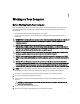
5. Lift up to remove the keyboard trim from the unit. Installing the Keyboard Trim 1. Align the keyboard trim to its compartment. 2. Press along the sides of the keyboard trim until it snaps in place. 3. Install the battery. 4. Follow the procedures in After Working Inside Your Computer. Removing the Keyboard 1. Follow the procedures in Before Working Inside Your Computer. 2. Remove: a) battery b) keyboard trim 3. Remove the screws that secure the keyboard to computer. 4.
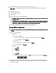
5. Lift and turn the keyboard to access the keyboard cable. 6. Disconnect the keyboard cable from the system board. 7. Remove the keyboard from the computer. 8. Peel back the adhesive tape securing the keyboard connector.
9. Remove the keyboard cable from the keyboard. Installing the Keyboard 1. Connect the keyboard cable and secure it to the keyboard using the tape. 2. Connect the keyboard cable to the system board. 3. Slide the keyboard into its compartment and ensure that it clicks into place. 4. Tighten the screws to secure the keyboard on the palmrest. 5. Flip the computer and tighten the screws to secure the keyboard. 6. Install: a) keyboard trim b) battery 7.
4. Slide the hard drive out of the computer. 5. Remove the screw that secures the hard-drive caddy to the hard drive. 6. Remove the hard-drive caddy from the hard drive. 7. Remove the hard-drive isolation from the hard drive.
Installing the Hard Drive 1. Install the hard-drive isolation on the hard drive. 2. Attach the hard-drive caddy to the hard drive. 3. Tighten the screws to secure the hard-drive caddy to the hard drive. 4. Slide the hard drive into the computer. 5. Tighten the screws to secure the hard drive to the computer. 6. Install the battery. 7. Follow the procedures in After Working Inside Your Computer. Removing the Optical Drive 1. Follow the procedures in Before Working Inside Your Computer. 2.
5. Remove the screw that secures the optical-drive latch to the optical drive assembly. 6. Push the optical-drive latch forward and remove it from the optical-drive assembly. 7. Remove the screws that secure the optical-drive latch bracket to the optical-drive assembly 8. Remove the latch bracket from the optical drive.
9. Remove the optical-drive door from the optical drive. Installing the Optical Drive 1. Secure the optical-drive door to the optical drive. 2. Install the latch bracket to the optical drive. 3. Tighten the screws to secure the optical-drive latch bracket to the optical drive assembly. 4. Secure the optical-drive latch to the optical drive assembly. 5. Tighten the screw to secure the optical drive latch. 6. Slide the optical drive into its slot. 7.
4. Remove the memory module from its connector on the system board. 5. Repeat steps 2 and 3 to remove the second memory module. Installing the Memory 1. Insert the memory module into the memory socket. 2. Press the securing clips to secure the memory module to the system board. 3. Install: a) base cover b) battery 4. Follow the procedures in After Working Inside Your Computer. Removing the Processor 1. Follow the procedures in Before Working Inside Your Computer. 2.
4. Remove the processor from the computer. Installing the Processor 1. Align the notches on the processor and the socket, and insert the processor into the socket. 2. Rotate the processor cam lock in a clockwise direction. 3. Install: a) heat sink b) base cover c) battery 4. Follow the procedures in After Working Inside Your Computer. Removing the Wireless Local Area Network (WLAN) Card 1. Follow the procedures in Before Working Inside Your Computer. 2. Remove: a) battery b) base cover 3.
4. Remove the screw that secures the WLAN card to the computer. 5. Remove the WLAN card from its slot on the system board. Installing the WLAN Card 1. Insert the WLAN card into its connector at a 45–degree angle into its slot. 2. Connect the antenna cables to their respective connectors marked on the WLAN card. 3. Tighten the screw to secure the WLAN card to the computer. 4. Install: a) base cover b) battery 5. Follow the procedures in After Working Inside Your Computer.
3. Disconnect the heat-sink cable. 4. Remove the screws that secure the heat sink to the system board. 5. Remove the heat sink from the computer. Installing the Heat Sink 1. Slide the heat sink into its original position in the system board. 2. Tighten the screws to secure the heat sink to the system board 3. Connect the heat-sink cable to the system board. 4. Install: a) base cover b) battery 5. Follow the procedures in After Working Inside Your Computer.
Removing the Bluetooth Card 1. Follow the procedures in Before Working Inside Your Computer. 2. Remove the: a) battery b) base cover 3. Remove the screw that secures the bluetooth card to the computer. 4. Disconnect the bluetooth cable from the system board. 5.
6. Disconnect the bluetooth cable from the bluetooth card. Installing the Bluetooth Card 1. Connect the bluetooth cable to the bluetooth card. 2. Connect the other end of the bluetooth cable to the system board. 3. Place the bluetooth card in its location in the computer. 4. Tighten the screw to secure the bluetooth card to the system board. 5. Install: a) base cover b) battery 6. Follow the procedures in After Working Inside Your Computer. Removing the Modem Card 1.
4. Lift the modem card to release the tab from the connector on the back of the card. 5. Disconnect the modem cable from the modem card. 6. Grasp the modem card and remove the it from the computer. Installing the Modem Card 1. Insert the modem card in its slot 2. Seat the modem card, to ensure that the tab on the back of the card is engaged. 3. Connect the modem cable to the modem card. 4. Tighten the screw to secure the modem card. 5. Install: a) base cover b) battery 6.
Removing the Speakers 1. Follow the procedures in Before Working Inside Your Computer. 2. Remove: a) b) c) d) e) f) g) h) i) j) k) battery base cover hard drive keyboard trim keyboard display assembly palmrest media board (available in E6430/E6430 ATG only) ExpressCard cage bluetooth card system board 3. Remove the screws that secure the speakers to the computer. 4. Remove the speaker cable from the routing channel.
5. Remove the speakers from the computer. Installing the Speakers 1. Align the speakers in the original position and connect the speaker cables. 2. Tighten the screws to secure the speakers. 3. Install: a) b) c) d) e) f) g) h) i) j) k) 4. system board bluetooth card ExpressCard cage media board (available in E6430/E6430 ATG only) palmrest display assembly keyboard keyboard trim hard drive base cover battery Follow the procedures in After Working Inside Your Computer.
4. Pry the coin-cell battery upward and remove it from the computer. Installing the Coin-Cell Battery 1. Place the coin-cell battery in its slot. 2. Connect the coin-cell battery cable. 3. Install: a) base cover b) battery 4. Follow the procedures in After Working Inside Your Computer. Removing the ExpressCard Cage 1. Follow the procedures in Before Working Inside Your Computer. 2. Remove: a) b) c) d) e) f) g) h) 3.
4. Remove the ExpressCard cage from the computer. Installing the ExpressCard Cage 1. Place the ExpressCard cage into its compartment. 2. Tighten the screws to secure the ExpressCard cage to the computer. 3. Install: a) b) c) d) e) f) g) h) 4. palmrest display assembly keyboard keyboard trim bluetooth card hard drive base cover battery Follow the procedures in After Working Inside Your Computer. Removing the Power-Connector Port 1. Follow the procedures in Before Working Inside Your Computer. 2.
4. Remove the screw that secures the power-connector bracket to the computer. 5. Remove the power-connector bracket from the computer. 6. Remove the power-connector cable from the computer. Installing the Power-Connector Port 1. Connect the power-connector cable to the computer. 2. Install the power-connector bracket to its position in the computer. 3. Tighten the screw to secure the power-connector bracket to the computer. 4. Connect the power-connector cable to the system board. 5.
Removing the Power LED Board 1. Follow the procedures in Before Working Inside Your Computer. 2. Remove: a) b) c) d) e) f) g) h) i) battery base cover hard drive bluetooth module keyboard trim keyboard display assembly display bezel display panel 3. Disconnect the power LED board cable. 4. Remove the screw securing the power LED board to the display assembly. 5. Remove the power LED board from the display assembly.
Installing the Power LED Board 1. Place the power LED board in its compartment in the display assembly. 2. Tighten the screw to secure the LED board to the display assembly. 3. Connect the power LED board cable to the display assembly. 4. Install: a) b) c) d) e) f) g) h) i) 5. display panel display bezel display assembly keyboard keyboard trim bluetooth module hard drive base cover battery Follow the procedures in After Working Inside Your Computer. Removing the Input/Output (I/O) Board 1.
4. Remove the I/O board from the computer. Installing the Input Output (I/O) Board 1. Place the I/O board in its compartment. 2. Tighten the screws to secure the I/O board. 3. Install: a) b) c) d) e) f) g) h) i) j) k) l) 4. system board ExpressCard cage media board (available in E6430/E6430 ATG only) palmrest display assembly keyboard keyboard trim bluetooth card hard drive optical drive base cover battery Follow the procedures in After Working Inside Your Computer.
3. Remove the screw that secures the hard-drive support plate to the computer. 4. Lift the hard-drive support plate from the computer. Installing the Hard-Drive Support Plate 1. Place the hard-drive support plate in its compartment. 2. Tighten the screw to secure the hard drive support plate to the computer. 3. Install the: a) b) c) d) e) f) g) h) 4.
3. Remove the screws that secure the palmrest assembly to the base of the computer. 4. Flip the computer over and remove the screws that secure the palmrest assembly to the computer. 5. Disconnect the media board cable (available in E6430/E6430 ATG only). 6. Disconnect the touchpad cable.
7. Disconnect the fingerprint reader cable. 8. Lift and remove the palmrest from the computer. Installing the Palmrest 1. Align the palmrest assembly to its original position in the computer and snap it into place. 2. Connect the following cables: a) media board (available in E6430/E6430 ATG only) b) touchpad c) fingerprint reader 3. Tighten the screws to secure the palmrest to the computer. 4. Install: a) b) c) d) e) f) 5.
Removing the WiFi-Switch Board 1. Follow the procedures in Before Working Inside Your Computer. 2. Remove the: a) b) c) d) e) f) g) battery base cover hard drive optical drive keyboard trim keyboard palmrest 3. Disconnect the WiFi-switch board cable from the system board. 4. Remove the screw that secures the WiFi-switch board. 5. Peel of the adhesive tape on the back of the WiFi-switch board and remove the WiFi-switch board.
Installing the WiFi-Switch Board 1. Fix the adhesive tape on the back of the WiFi-switch board and place the board in its slot. 2. Tighten the screw to secure the WiFi-switch board. 3. Connect the WiFi-switch board cable to the system board. 4. Install: a) b) c) d) e) f) g) 5. palmrest keyboard keyboard trim optical drive hard drive base cover battery Follow the procedures in After Working Inside Your Computer. Removing the System Board 1.
4. Remove the screws that secure the LVDS support bracket. 5. Remove the LVDS support bracket from the computer. 6. Disconnect the LVDS cable from the system board. 7. Remove the antenna cables from the routing channel.
8. Disconnect the coin-cell battery cable. 9. Disconnect the speaker cable from the top side of the system board. 10. Disconnect the WiFi-board cable. 11. Remove the screws that secure the system board.
12. Lift the edge of the system board to a 45–degree angle. 13. Release the system board from the ports and connectors. 14. Lift the system board from the computer. Installing the System Board 1. Place the system board on the chassis. 2. Tighten the screws to secure the system board to the computer. 3. Connect the following cables to the system board: a) b) c) d) WiFi-switch board speaker coin-cell battery LVDS 4. Route the antenna cables through the routing channels. 5.
8. Install the: a) b) c) d) e) f) g) h) i) j) k) l) m) 9. ExpressCard cage palmrest processor heat sink modem card WLAN card keyboard keyboard trim bluetooth card optical drive hard drive base cover battery Follow the procedures in After Working Inside Your Computer. Removing the Modem Connector 1. Follow the procedures in Before Working Inside Your Computer. 2. Remove: a) b) c) d) e) f) g) h) i) j) k) 3.
4. Remove the modem cable from the routing channel. 5. Remove the screw that secures the modem-connector bracket to the computer. 6. Remove the modem-connector bracket from the computer. 7. Remove the modem connector from the computer.
Installing the Modem Connector 1. Place the modem connector in its compartment. 2. Place the modem-connector bracket on the connector. 3. Tighten the screw to secure the modem-connector bracket. 4. Route the modem connector cable. 5. Connect the modem-card cable to the modem card. 6. Install: a) b) c) d) e) f) g) h) i) j) k) 7.
4. Remove the LVDS support bracket from the system board. 5. Disconnect the LVDS cable. 6. Disconnect the camera cable from the system board. 7. Remove the LVDS cable from the routing channel.
8. Remove the screws to release the display assembly on both sides. 9. Lift the display assembly and pull the LVDS and the antenna cables through the opening of the computer. 10. Remove the display assembly from the computer. Installing the Display Assembly 1. Place the display assembly onto the computer. 2. Insert the LVDS and wireless antenna cables through the holes on the base chassis and connect them. 3. Tighten the screws on both corners to secure the display assembly. 4.
8. Install: a) base cover b) battery 9. Follow the procedures in After Working Inside Your Computer. Removing the Display Bezel 1. Follow the procedures in Before Working Inside Your Computer. 2. Remove the battery. 3. Pry up the bottom edge of the display bezel. 4. Pry up the left, right and top edges of the display bezel. 5. Remove the display bezel from the display assembly. Installing the Display Bezel 1. Place the display bezel onto the display assembly. 2.
3. Press on the left and right edges of the display bezel. 4. Install the battery. 5. Follow the procedures in After Working Inside Your Computer. Removing the Display Panel 1. Follow the procedures in Before Working Inside Your Computer. 2. Remove: a) battery b) display assembly c) display bezel 3. Remove the screws that secure the display panel to the display assembly. 4. Flip the display panel over. 5.
6. Remove the display panel from the display assembly. Installing the Display Panel 1. Connect the LVDS cable and stick the LVDS cable connector tape. 2. Flip the display and place it in the display assembly. 3. Tighten the screws to secure the display panel to the display assembly. 4. Install: a) display bezel b) display assembly c) battery 5. Follow the procedures in After Working Inside Your Computer. Removing the Display Assembly 1. Follow the procedures in Before Working On Your Computer.
4. Remove the LVDS support bracket from the system board. 5. Disconnect the LVDS cable. 6. Disconnect the camera cable from the system board. 7. Remove the LVDS cable from the routing channel.
8. Remove the screws to release the display assembly on both sides. 9. Lift the display assembly and pull the LVDS and the antenna cables through the opening of the computer. 10. Remove the display assembly from the computer. Installing the Display Assembly 1. Place the display assembly onto the computer. 2. Insert the LVDS and wireless antenna cables through the holes on the base chassis and connect them. 3. Tighten the screws on both corners to secure the display assembly. 4.
8. Install: a) base cover b) battery 9. Follow the procedures in After Working Inside Your Computer. Removing the Display-Hinge Caps 1. Follow the procedures in Before Working Inside Your Computer. 2. Remove: a) b) c) d) e) f) g) battery base cover hard drive bluetooth card keyboard trim keyboard display assembly 3. Rotate the left and right hinges upwards to a vertical position. 4. Pry loose the edge of hinge cap from the hinge and remove the hinge caps from the display assembly.
4. Install: a) b) c) d) e) f) g) 5. display assembly keyboard keyboard trim bluetooth card hard drive base cover battery Follow the procedures in After Working Inside Your Computer. Removing the Display Hinges 1. Follow the procedures in Before Working Inside Your Computer. 2. Remove: a) b) c) d) e) f) g) h) i) battery base cover hard drive bluetooth card keyboard trim keyboard display assembly display bezel display panel 3.
5. Remove the screws that secures the display hinges to the display assembly. 6. Remove the display hinges from the display assembly. Installing the Display Hinges 1. Place both the display hinges on the panel. 2. Tighten the screws to secure the display hinges to the display assembly. 3. Place the display hinge plates on the hinges. 4. Tighten the screws to secure the display hinge plates to the display assembly. 5. Install: a) b) c) d) e) f) g) h) i) 6.
Removing the Camera 1. Follow the procedures in Before Working Inside Your Computer. 2. Remove: a) b) c) d) battery display assembly display bezel display panel 3. Disconnect the LVDS and camera cable from the camera. 4. Remove the screw that secures the camera to the display assembly. 5. Remove the camera from the display assembly. Installing the Camera 1. Install the camera in its slot on the display panel. 2. Tighten the screw to secure the camera to the display assembly.
3. Connect the LVDS and the camera cable to the camera. 4. Install: a) b) c) d) 5. display panel display bezel display assembly battery Follow the procedures in After Working Inside Your Computer. Removing the LVDS and Camera Cable 1. Follow the procedures in Before Working Inside Your Computer. 2. Remove: a) b) c) d) e) f) g) h) i) j) battery base cover hard drive bluetooth card keyboard trim keyboard display assembly display bezel display panel display hinges 3.
5. Remove the LVDS and camera cable from the display assembly. Installing the LVDS and Camera Cable 1. Route the LVDS and camera cable on the display assembly. 2. Fix the adhesive the tape to secure the cable. 3. Connect the LVDS and camera cable to the camera. 4. Install: a) b) c) d) e) f) g) h) i) j) 5. 60 display hinges display panel display bezel display assembly keyboard keyboard trim bluetooth card hard drive base cover battery Follow the procedures in After Working Inside Your Computer.
Additional Information 3 This section provides information for the additional features that are part of your computer. Docking Port Information The docking port is used for connecting the laptop to a docking station (optional). 1.
System Setup 4 System Setup enables you to manage your computer hardware and specify BIOS‐level options.
Keys Navigation Allows you to select a value in the selected field (if applicable) or follow the link in the field. Spacebar Expands or collapses a drop‐down list, if applicable. Moves to the next focus area. NOTE: For the standard graphics browser only. Moves to the previous page till you view the main screen. Pressing in the main screen displays a message that prompts you to save any unsaved changes and restarts the system. Displays the System Setup help file.
Option Description • • Parallel Port Allows you to define and set how the parallel port on the docking station operates. You can set the parallel port to: • • • • Serial Port Enabled Enabled w/PXE (Default Setting) Disabled AT PS2 ECP Identifies and defines the serial port settings. You can set the serial port to: • • • • • Disabled COM1 (Default Setting) COM2 COM3 COM4 NOTE: The operating system may allocate resources even if the setting is disabled.
Option Description • USB Configuration Enable SMART Reporting — This option is disabled by default. Allows you to define the USB configuration. The options are: • • Enable Boot Support Enable External USB Port Default Setting: both the options are enabled. USB PowerShare Allows you to configure the behavior of the USB PowerShare feature. This option is disabled by default. • Keyboard Illumination Allows you to choose the operating mode of the keyboard illumination feature.
Table 4. Video Option Description LCD Brightness Allows you to set the panel brightness when the ambient sensor is Off. Optimus Allows you to enable or disable the NVIDIA Optimus technology. • Enable Optimus — Default Setting. Table 5. Security Option Description Intel TXT (LT-SX) Configuration This option is disabled by default. Admin Password Allows you to set, change, or delete the administrator (admin) password.
Option Description Default Setting: Enable CPU XD Support Computrace Allows you to activate or disable the optional Computrace software The options are: • • • Deactivate (Default Setting) Disable Activate NOTE: The Activate and Disable options will permanently activate or disable the feature and no further changes will be allowed CPU XD Support Allows you to enable the Execute Disable mode of the processor.
Option Description Hyper-Thread Control Allows you to enable or disable the HyperThreading in the processor. Default Setting: Enabled Table 7. Power Management Option Description AC Behavior Allows the computer to power on automatically, when AC adapter is plugged. The option is disabled. • Auto On Time Allows you to set the time at which the computer must turn on automatically.
Option Description • Custom Charge — you can set the percentage to which the battery must charge. NOTE: All charging modes may not be available for all the batteries. Battery Slice Configuration Allows you to define the how to charge the battery. The options are: • • Standard Charge Express Charge (Default Setting) Table 8. POST Behavior Option Description Adapter Warnings Allows you to activate the adapter warning messages when certain power adapters are used. This option is enabled by default.
Table 9. Virtualization Support Option Description Virtualization Specifies whether a Virtual Machine Monitor (VMM) can utilize the additional hardware capabilities provided by Intel Virtualization Technology. • VT for Direct I/O Enable Intel Virtualization Technology - Default Setting. Enables or disables the Virtual Machine Monitor (VMM) from utilizing the additional hardware capabilities provided by Intel Virtualization technology for direct I/O.
Updating the BIOS It is recommended to update your BIOS (system setup), on replacing the system board or if an update is available. For laptops, ensure that your computer battery is fully charged and connected to a power outlet 1. Re-start the computer. 2. Go to dell.com/support. 3. Enter the Service Tag or Express Service Code and click Submit. NOTE: To locate the Service Tag, click Where is my Service Tag? NOTE: If you cannot find your Service Tag, click Detect My Product.
NOTE: If the password jumper is disabled, the existing System Password and Setup Password is deleted and you need not provide the system password to log on to the computer. To enter a system setup, press immediately after a power-on or re-boot. 1. In the System BIOS or System Setup screen, select System Security and press . The System Security screen appears. 2. In the System Security screen, verify that Password Status is Unlocked. 3.
Diagnostics 5 If you experience a problem with your computer, run the ePSA diagnostics before contacting Dell for technical assistance. The purpose of running diagnostics is to test your computer's hardware without requiring additional equipment or risking data loss. If you are unable to fix the problem yourself, service and support personnel can use the diagnostics results to help you solve the problem.
Troubleshooting Your Computer 6 You can troubleshoot your computer using indicators like Diagnostic Lights, Beep Codes, and Error Messages during the operation of the computer. Device Status Lights Table 13. Device Status Lights Turns on when you turn on the computer and blinks when the computer is in a power management mode. Turns on when the computer reads or writes data. Turns on steadily or blinks to indicate battery charge status. Turns on when wireless networking is enabled.
Battery Status Lights If the computer is connected to an electrical outlet, the battery light operates as follows: Alternately blinking amber light and white light An unauthenticated or unsupported non-Dell AC adapter is attached to your laptop. Alternately blinking amber light with steady white light Temporary battery failure with AC adapter present. Constantly blinking amber light Fatal battery failure with AC adapter present. Light off Battery in full charge mode with AC adapter present.
Technical Specifications 7 NOTE: Offerings may vary by region. The following specifications are only those required by law to ship with your computer. For comprehensive specification of your computer go to Specifications’ section in your Owner’s Manual available on the support site at dell.com/support. For more information about the configuration of your computer, go to Help and Support in your Windows operating system and select the option to view information about your computer. Table 15.
Feature Specification NOTE: The computer supports up to the maximum of 16 GB memory; however, a 32-bit operating systems, such as the 32-bit version of Microsoft® Windows® XP, can only use a maximum of 4 GB of address space. Moreover, certain components within the computer require address space in the 4 GB range. Any address space reserved for these components cannot be used by computer memory; therefore, the amount of memory available to a 32-bit operating system is less than 4 GB.
Table 21. Ports and Connectors Features Specification Audio one microphone/stereo headphone/speakers connector Video • • Network adapter one RJ-45 connector USB 2.0 • • USB 3.0 two Memory card reader one 8-in-1 memory card reader Docking port one Subscriber Identity Module (SIM) card one one 15-pin VGA connector 19-pin HDMI connector one 4-pin USB 2.0-compliant connector one eSATA/USB 2.0-compliant connector Table 22.
Feature Specification • Maximum Brightness 1600 x 900 pixels 200 nits Latitude E6530: Height 210 mm (8.26 inches) Width 360 mm (14.17 inches) Diagonal 394.24 mm (15.60 inches) Active area (X/Y) 344.23 mm x 193.54 mm Maximum resolution • • • Maximum Brightness 220 nits 1366 x 768 pixels 1600 x 900 pixels 1920 x 1080 pixels Latitude E6430 ATG: Height 192.5 mm (7.57 inches) Width 324 mm (12.75 inches) Diagonal 355.60 mm (14.00 inches) Active area (X/Y) 357.30 mm x 246.
Table 24. Keyboard Feature Specification Number of keys United States: 86 keys, United Kingdom: 87 keys, Brazil: 87 keys, and Japan: 90 keys NOTE: Numeric keypad is available for Latitude E6530. Layout QWERTY/AZERTY/Kanji Table 25. Touchpad Feature Specification Active Area: X-axis 80.00 mm Y-axis 45.00 mm Table 26.
Feature Specification 6-cell / 9-cell 11.10 VDC Temperature range: Operating 0 °C to 35 °C (32 °F to 95 °F) Non-Operating –40 °C to 65 °C (–40 °F to 149 °F) Coin-cell battery 3 V CR2032 lithium coin cell Table 27. AC Adapter Feature Specification Type 65 W STD and 65 W BFR/PVC free d90 W adapter Input voltage 100 VAC to 240 VAC 100 VAC to 240 VAC Input current (maximum) 1.50 A 1.60 A Input frequency 50 Hz to 60 Hz 50 Hz to 60 Hz Output power 65 W 90 W Output current 3.
Feature Specification Operating 10 % to 90 % (non condensing) Storage 5 % to 95 % (non condensing) Altitude (maximum): Operating –15.24 m to 3048 m (–50 ft to 10,000 ft) Non-Operating –15.24 m to 10,668 m (–50 ft to 35,000 ft) Airborne contaminant level G1 as defined by ISA-71.
Contacting Dell 8 To contact Dell for sales, technical support, or customer service issues: 1. Visit support.dell.com. 2. Verify your country or region in the Choose a Country/Region drop-down menu at the bottom of the page. 3. Click Contact Us on the left side of the page. 4. Select the appropriate service or support link based on your need. 5. Choose the method of contacting Dell that is convenient for you.