Dell™ Latitude™ L400 User's Guide Preface Introduction Setup and Operation Powering Your Computer Traveling With Your Computer Intel SpeedStep Options Installing Drivers and Utilities Customizing Your Computer Replacing the Hard-Disk Drive Troubleshooting Your Computer Technical Specifications Getting Help Model PP01S Information in this document is subject to change without notice. © 2000 Dell Computer Corporation. All rights reserved.
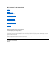
Back to Contents Page AC Adapter: Dell™ Latitude™ L400 User's Guide Using the AC Adapter Connecting the AC Adapter Turning On the Computer Using the AC Adapter The AC adapter converts AC power from an electrical outlet to the DC power used by the computer. The AC adapter kit includes the AC adapter with its attached DC cable (which connects to the computer) as well as an AC power cable that connects the adapter to an electrical outlet.
Back to Contents Page
Back to Contents Page Power Management Settings: Dell™ Latitude™ L400 User's Guide Experimenting With Power Conservation Suspend-to-Disk Mode for Windows NT Using Key Combinations Hibernate Mode for Windows 98, Windows 2000, and Windows Me Closing the Display Power Management Properties for Windows 98 Suspend Mode Power Management Properties for Windows NT Standby Mode Power Options Properties for Windows 2000 and Windows Me Experimenting With Power Conservation In general, the lower the value yo
One way to conserve power on the computer is to close the display when the computer is not in use. When you close the display and an external monitor is not connected, the computer's display shuts off and, depending on how you set the Lid Close option on the Power screen in the system setup program, the computer may enter suspend mode (standby mode in Windows 98, Windows 2000, and Windows Me).
Some PC Cards may not operate correctly after resuming from S2D mode. If you encounter problems with a card, remove and reinsert the card. NOTE: Dell creates an appropriately sized S2D file before shipping the computer to you. Use the Suspend-to-Disk Utility to remove the file, to increase the size of the file, or to add the S2D file if you removed it. For information on creating a S2D file, see "Suspend-to-Disk Utility.
l l l Power Meter — allows you to view the percentage of battery life remaining when your computer is operating on battery power. If your computer is operating on AC power, the computer displays a message. Advanced — allows you to display the Power Meter on the Windows 98 taskbar and to display a password prompt when the computer resumes operation from standby mode. Advanced also allows you to define the action of the Power buttons. Hibernate — allows you to enable hibernate mode in Windows 98.
Back to Contents Page Batteries: Dell™ Latitude™ L400 User's Guide About the Batteries Second Low-Battery Warning Using the Battery Detecting Battery Problems Charging the Battery Battery Disposal Charging a Hot Battery About Battery Power Replacing the Battery Battery Auto-Learning Utility Battery Charge Gauge Turning On the Computer First Low-Battery Warning About the Batteries Your computer includes a 4-cell or 6-cell lithium ion battery that provides power when an electrical outlet is no
When you activate standby mode (known as suspend in Microsoft® Windows NT®), the computer can remain in standby mode on battery power for approximately one week (if the battery was fully charged before activating suspend or standby mode). If you are going to store the computer, disconnect all devices and turn off the computer. Remove the battery when you store your computer for an extended period of time. A battery will drain when not in use during prolonged storage.
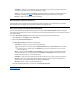
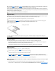
3. Remove the battery from the battery bay. Close the computer display and turn the computer over. Slide the battery bay latch to the unlock position (see Figure 2), causing the battery to pop up slightly on one side. While keeping the latch in the unlock position, pivot the battery up and out of the bay. Release the latch. Figure 2. Removing a Battery 4. Position the new battery as shown in Figure 2, and lower the outside edge of the battery into the battery compartment.
l l l l If one indicator lights up, the battery has 1 to 25 percent of its charge remaining. If two indicators light up, the battery has 26 to 50 percent of its charge remaining. If three indicators light up, the battery has 51 to 75 percent of its charge remaining. If four indicators light up, the battery has 76 to 100 percent of its charge remaining.
Do not dispose of these batteries along with household waste. Contact your local waste disposal agency for the address of the nearest battery deposit site. About Battery Power You automatically conserve battery power each time you connect the computer to an electrical outlet. The battery is even being recharged when you use AC power. The battery's life expectancy is largely determined by the number of charges it receives, so use an electrical outlet to run the computer whenever possible.
Back to Contents Page CD-ROM, DVD-ROM, and CD-RW Drives: Dell™ Latitude™ L400 User's Guide Using the Drives Caring for CDs, DVDs, and CD-RW Discs Types of Supported Discs Using the Drives CD-ROM and DVD-ROM drives are read-only devices that can play most commercially available 8- or 12-centimeter (cm) sound and video CDs. CD-rewritable (CD-RW) drives can write to and play CD-RWs and can play CDs. Dell has installed the appropriate CD-ROM and CD-RW device drivers on your hard-disk drive.
l CD-I (mode-2 form 1 and form 2) l CD-I Ready l CD-Bridge l Photo CD, CD-recordable (CD-R) (single and multisession) l Video CD l CD-RW (The 24x CD-ROM and DVD-ROM drives can read, but not write to, CD-RWs; only the CD-RW drive can write to this type of disc.
Back to Contents Page Contacting Dell: Dell™ Latitude L400 User's Guide Overview Europe Contact Numbers International Dialing Codes Asia and Other Regions Contact Numbers Americas Contact Numbers Overview When you need to contact Dell, use the telephone numbers, codes, and electronic addresses provided in the following sections. "International Dialing Codes" provides the various codes required to make long-distance and international calls.
Germany (Langen) 00 49 6103 Hong Kong 001 852 Not required Ireland (Bray) 16 353 1 Italy (Milan) 00 39 02 Japan (Kawasaki) 001 81 44 Korea (Seoul) 001 82 2 Luxembourg 00 352 — Macau — 853 Not required Malaysia (Penang) 00 60 4 Mexico (Colonia Granada) 95 52 5 Netherlands (Amsterdam) 00 31 20 New Zealand 00 64 — Norway (Lysaker) 095 47 Not required Poland (Warsaw) 011 48 22 Portugal 00 35 — Singapore (Singapore) 005 65 Not required 09/091 27 1
Chile call the U.S.A. for sales, customer, and technical assistance Latin America Customer Technical Support (Austin, Texas, U.S.A.) 512 728-4093 512 728-3619 512 728-3883 Sales (Austin, Texas, U.S.A.) 512 728-4397 SalesFax (Austin, Texas, U.S.A.) 512 728-4600 728-3772 Mexico Automated Order-Status System (Austin, Texas, U.S.A.) 512 728-0685 NOTE: Customers in Mexico call the U.S.A. for access to the Automated Order-Status System and AutoTech.
Europe Contact Numbers Area Code Local Number or Toll-Free Number Country (City) Department Name or Service Austria (Vienna) Switchboard 01 491 040 Home/Small Business Sales 01 795676-02 NOTE: Customers in Austria call Langen, Germany for Technical Support and Customer Care. Home/Small Business Sales Fax 01 795676-05 Home/Small Business Customer Care 01 795676-03 0660-8056 01 795676-04 Preferred Accounts/Corporate Technical Support 0660-8779 Web site: http://support.euro.dell.
Customer Care 0825 823 833 Fax 0825 004 701 Switchboard 0825 004 700 Switchboard (Alternative) 04 Sales 0825 004 700 Web site: http://support.euro.dell.com E-mail: web_fr_tech@dell.com Corporate Technical Support 0825 004 719 Customer Care 0825 338 339 Fax 01 55 94 71 99 Switchboard 01 55 94 71 00 01 55 94 71 00 Sales Web site: http://support.euro.dell.com E-mail: web_fr_tech@dell.
E-mail: web_it_tech@dell.com Luxembourg Technical Support (Brussels, Belgium) NOTE: Customers in Luxembourg call Belgium for sales, customer, and technical assistance. Home/Small Business Sales (Brussels, Belgium) Netherlands (Amsterdam) 02 481 92 88 toll free: 080016884 Corporate Sales (Brussels, Belgium) 02 481 91 00 Customer Care (Brussels, Belgium) 02 481 91 19 Switchboard (Brussels, Belgium) 02 481 91 00 Fax (Brussels, Belgium) 02 481 92 99 Web site: http://support.euro.
Web site: http://support.euro.dell.com E-mail: web_esp_tech@dell.com Corporate Technical Support 902 100 130 Customer Care 902 118 546 Switchboard 91 722 92 00 Fax 91 722 95 83 Web site: http://support.euro.dell.com E-mail: web_esp_tech@dell.
Customer Technical Support (Penang, Malaysia) 633 4966 Customer Service (Penang, Malaysia) 633 4949 Transaction Sales (Penang, Malaysia) 633 4955 China (Xiamen) Technical Support toll free: 800 858 2437 Customer Experience toll free: 800 858 2060 Home and Small Business toll free: 800 858 2222 Preferred Accounts Division toll free: 800 858 2062 Large Corporate Accounts Hong Kong Technical Support Customer Service (Penang, Malaysia) 633 4949 T
for customer assistance. Corporate Sales South Africa (Johannesburg) Technical Support 011 709 7710 Customer Care 011 709 7707 Sales 011 709 7700 Fax 011 709 0495 Switchboard 011 709 7700 Web site: http://support.euro.dell.com toll free: 800 6011 053 E-mail: dell_za_support@dell.
Back to Contents Page Customizing Your Computer: Dell™ Latitude™ L400 User's Guide Using the System Setup Program Power Management Settings Suspend-to-Disk Utility Back to Contents Page
Back to Contents Page Dell™ Diagnostics: Dell Latitude™ L400 User's Guide Overview Dell Diagnostics Main Screen Overview Features of the Dell Diagnostics Confirming the System Configuration Information When to Use the Dell Diagnostics How to Use Dell Diagnostics Starting the Dell Diagnostics Overview Unlike many diagnostic programs, the Dell Diagnostics helps you check your computer's hardware without any additional equipment and without destroying any data.
1. 2. 3. 4. Removable Devices ATAPI CD-ROM Drive Hard Disk Boot to LAN 5. Save the changes and exit the system setup program. 6. Insert your ResourceCD into the CD-ROM or DVD-ROM drive. 7. Turn the computer off. 8. Turn the computer on. The computer restarts and automatically begins to run the Dell Diagnostics. 9. When you have completed running diagnostics, remove your ResourceCD from the CD-ROM or DVD-ROM drive.
Confirming the System Configuration Information When you boot your computer from the Dell Latitude L400 ResourceCD, the diagnostics checks your system configuration information and displays it in the Device Groups area on the main screen.
Device Group describes the test group that is presently highlighted in the Device Groups list on the main menu screen. It also provides reasoning for using some tests. Device Category Device is the educational section of online Help. It describes the function and purpose of the highlighted device in the Device Groups.
Back to Contents Page Diskette Drive: Dell™ Latitude™ L400 User's Guide Your computer was shipped with a 3.5-inch diskette drive installed in the external media bay. For more information on using and installing devices in the external media bay, see "External Media Bay." The diskette drive lets you install programs and transfer data using 3.5-inch diskettes. To use the diskette drive, insert a 3.5-inch diskette into the drive (label side up and metal end first).
Back to Contents Page Display: Dell™ Latitude™ L400 User's Guide Adjusting the Brightness Dual-Display Mode Expanded Video Mode If You Have Display Problems Video Drivers and Video Resolution Cleaning the Display and Touch Pad Customizing Video Resolution Adjusting the Brightness To adjust the brightness of the display, you can use the key combinations shown in Table 1.
16 bpp = 65,536 colors 24 bpp = 16,777,256 colors 32 bpp = 4,294,967,296 colors Multiple-Display Operation Using a Single Controller With a single controller supporting multiple displays (computer display and external monitor), operation reflects Table 2 with the difference that the 1280 x 1024 resolution will cause both displays to pan at 24, 16, or 8 bpp.
6. Click the ATI Displays tab. 7. Set either the monitor or the display to Primary, and set the other viewing device to Secondary. (The primary viewing device will display the system icons and task bar.) 8. Click Apply. 9. Click Yes to confirm the settings. 10. Click OK to return to the Display Properties box. Two display icons appear in the window. 11. Select the secondary viewing device by double-clicking the display icon marked "2." 12.
Back to Contents Page Installing Drivers and Utilities: Dell™ Latitude™ L400 User's Guide Overview Installing Drivers and Utilities From the Dell Latitude L400 ResourceCD Overview All of your computer's utilities and all drivers for Dell-installed devices are operative when you receive the computer—no further installation or configuration is needed. However, if you ever need to reinstall any of the drivers or utilities, use the Dell Latitude L400 ResourceCD that you received with your computer.
Back to Contents Page Error Messages, IRQs, and Memory Assignments: Dell™ Latitude™ L400 User's Guide Error Messages Memory Allocations Avoiding IRQ Assignment Conflicts I/O Memory Map Error Messages Your application programs, operating system, and the computer itself can identify problems and alert you to them. When this occurs, a message may appear on the computer's display or on an external monitor (if one is attached).
it may be faulty. A key on the built-in keyboard may have been pressed while the computer was booting. be corrected, call Dell for technical assistance. 0250:System battery is dead—Replace and run Setup The system battery does not have enough charge to power the computer. Connect the computer to electrical power to recharge the battery, or replace the battery. Then check your system setup program settings.
NOTE: To view memory allocations in Windows 98, click the Start button, point to Settings, and click Control Panel. Double-click the System icon. Click the Device Manager tab, and then double-click Computer. Windows 2000 handles memory allocations automatically. Refer to your Windows 2000 documentation for more information. Table 3.
0062-0062 ACPI-compliant embedded controller 0064-0064 Keyboard controller 0066-0066 ACPI-compliant embedded controller 0070-007F RTC and NMI enable 0080-009F DMA page registers 00A0-00BF Interrupt controller #2 00C0-00DF DMA controller #2 00F0-00FF Math coprocessor 0170-0177 CD-ROM drive controller 01F0-01F7 Hard-disk drive controller 0376-0376 IDE controller 0378-037F LPT1 0398-0399 System board resources 03B0-03BB VGA 03C0-03DF VGA 03E0-03E1 PC Card controller 03F2-03F5;
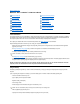
Back to Contents Page Connecting External Devices: Dell™ Latitude™ L400 User's Guide About the I/O Connectors AC Adapter Mouse, Keyboard, and External Numeric Keypad Audio Devices USB Devices Modem Connector Parallel Devices NIC Connector Advanced Port Replicator External Media Options External Monitor About the I/O Connectors You can connect external devices to the input/output (I/O) connectors on the back and left side of the computer (see Figure 1).
When you attach a PS/2 mouse to the computer, the touch pad is automatically disabled if the Internal Touchpad option in the system setup program is set to Auto Disabled (the default). To keep the touch pad enabled while an external pointing device is attached to the computer, go to the Advanced screen of the system setup program and set Internal Touchpad to Enabled. If you are using a PS/2-compatible mouse that is not made by Microsoft and the mouse does not work properly, reboot the computer.
NOTICE: When the diskette drive is not being used externally, remove the parallel diskette-drive cable from the parallel connector. NOTICE: Use the parallel diskette-drive cable only with the diskette drive. Do not try to connect any other device to the computer with this cable. The drive access indicator does not blink when data is being accessed from the diskette drive connected to the parallel connector. NOTICE: Protect the diskette drive when it is not in the external media bay.
To toggle the video image between the display, an external monitor, or both simultaneously, press on the keyboard. Press on an external keyboard if the External Hot-Key option on the Advanced screen in the system setup program is enabled. If the external monitor is turned off when you boot your computer, the computer still sends the video image to the external monitor, but you will not see an image on either the computer's display or the external monitor.
Back to Contents Page Getting Help: Dell™ Latitude™ L400 User's Guide Help Overview Contacting Dell Back to Contents Page
Back to Contents Page Help Overview: Dell™ Latitude™ L400 User's Guide Technical Assistance Product Information Help Tools Returning Items for Warranty Repair or Credit Problems With Your Order Before You Call Technical Assistance If you need assistance with a technical problem, perform the following steps: 1. Run the Dell Diagnostics. 2. Make a copy of the Diagnostics Checklist and fill it out. 3. Use Dell's extensive suite of online services available at Dell's World Wide Web site (http://www.dell.
support@us.dell.com apsupport@dell.com (for Asian/Pacific countries only) support.euro.dell.com (for Europe only) l Electronic Quote Service sales@dell.com apmarketing@dell.com (for Asian/Pacific countries only) l Electronic Information Service info@dell.com AutoTech Service Dell's automated technical support service—AutoTech—provides recorded answers to the questions most frequently asked by Dell customers about their portable and desktop computer systems.
3. Include a copy of the Diagnostics Checklist indicating the tests you have run and any error messages reported by the Dell Diagnostics. 4. Include any accessories that belong with the item(s) being returned (power cables, software diskettes, guides, and so on) if the return is for credit. 5. Pack the equipment to be returned in the original (or equivalent) packing materials. You are responsible for paying shipping expenses.
Back to Contents Page Introduction: Dell™ Latitude™ L400 User's Guide Overview Available Options Features Getting Help Overview Dell Latitude L400 portable computers are expandable multimedia systems designed around an Intel® Mobile Pentium® III microprocessor that includes Peripheral Component Interconnect (PCI) and Intel SpeedStep™ technologies. This section describes the major hardware and software features of your computer.
1 USB connector 2 Speakers and headphones (line-out/speaker-out) jack 3 Microphone (MIC IN) jack 4 Fan intake/exhaust vents 5 Air inlet 6 PS/2 connector 7 AC adapter connector 8 External media bay connector 9 Parallel connector 10 Video connector 11 Modem connector 12 NIC connector 13 External media bay Figure 3.
l l l System memory consisting of 64, 128, or 256 MB (optional at time of purchase) of synchronous dynamic random-access memory (SDRAM) small outline, dual-inline memory modules (SODIMMs). Two power conservation modes—suspend (or standby) mode and suspend-to-disk (S2D) mode—that help you conserve battery power. If the batteries run out of power, S2D mode prevents data loss by copying all system data to the hard-disk drive and turning off the computer. Connector for one 3.3-volt (V) or 5-V PC Card.
l External pointing devices l External speakers, headphones, and microphones l Printers l Dell Latitude storage devices such as hard-disk drives, CD-ROM drives, CD-RW drives, DVD-ROM drives, and Zip 250 drives l AC adapter l PC Cards l Carrying cases Instructions for connecting or installing these options are included in the upgrade kit you receive from Dell. For more information on options available for your computer, visit the Dell World Wide Web site at http://support.dell.com.
Back to Contents Page Keyboard: Dell™ Latitude™ L400 User's Guide Embedded Numeric Keypad Speaker Key Combinations Display Key Combinations System Function Key Combinations Power Conservation Key Combinations CD-ROM and DVD-ROM Drive Key Combinations Embedded Numeric Keypad As you work, you may want to use the embedded numeric keypad (see Figure 1) to enter numbers in spreadsheet or financial programs. The embedded numeric keypad shares some of the keys on your computer's keyboard.
NOTE: The key combinations in Table 3 can be used from an external keyboard by enabling the External Hot-Key option on the Advanced screen in the system setup program, and then pressing instead of . Use the key combinations in Table 3 to activate or turn off the computer's power conservation features. Table 3.
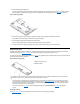
Back to Contents Page External Media Bay: Dell™ Latitude™ L400 User's Guide You can use the external media bay (see Figure 1) for the diskette drive that comes with your system. Alternatively, you can install an optional device (such as a CD-ROM, CD-RW, DVD-ROM, Zip 250, or non-bootable second hard-disk drive) in the bay. NOTE: If desired, you can use the media bay cable to connect a device directly to the external media bay connector, without using the external media bay.
1 Fan intake/exhaust vents 2 Air inlet 5. If your computer is running Softex Bay Manager: Click OK at the Softex Bay Manager screen. Click OK at the Device Removal screen (if it appears), and then click OK at the Device Configured screen. If you turned off the computer in step 1: Press the power button to turn the computer back on.
Back to Contents Page Media Options: Dell™ Latitude™ L400 User's Guide External Media Bay CD-ROM, DVD-ROM, and CD-RW Drives Diskette Drive Back to Contents Page
Back to Contents Page PC Cards: Dell™ Latitude™ L400 User's Guide About PC Cards Removing PC Cards Using a PC Card NIC Configuring PC Cards Installing PC Cards About PC Cards On the right side of the computer is a PC Card slot in which you can install PC Cards that comply with Release 2.01 of the Personal Computer Memory Card International Association (PCMCIA) standard and Release 4.2 of the Japanese Electronic Industry Development Association (JEIDA) standard.
1. If necessary, remove the blank from the PC Card slot. Press the eject button once to pop the button out, press it again to eject the blank partway, and then pull the blank out. 2. Make sure that the eject button is pressed all the way in. Hold the card with its orientation symbol pointing into the slot and the top side of the card facing up. 3. Insert the card into the slot and press in firmly until the card is completely seated in the internal PC Card connector. 4.
l If drivers are not available on the hard-disk drive, prompts you to install them by using the device driver diskette that came with the card The operating system automatically detects a PC Card and opens the Add New Hardware menu from the Control Panel. For information, see the PC Card operating system documentation.
Back to Contents Page Powering Your Computer: Dell™ Latitude™ L400 User's Guide AC Adapter Power Management Settings Batteries Back to Contents Page
Back to Contents Page Preface: Dell™ Latitude™ L400 User's Guide About This Guide Notational Conventions Warranty and Return Policy Information Typographical Conventions Other Documents You May Need About This Guide This guide is intended for anyone who uses a Dell Latitude L400 portable computer. It can be used by both first-time and experienced computer users who want to learn about the features of the computer.
advanced technical reference material intended for experienced users or technicians. Notational Conventions The following subsections list notational conventions used in this document. Notes, Notices, and Cautions Throughout this guide, blocks of text may be accompanied by an icon and printed in bold type or in italic type. These blocks are notes, notices, and cautions, and they are used as follows: NOTE: A NOTE indicates important information that helps you make better use of your computer.
Back to Contents Page
Back to Contents Page Replacing the Hard-Disk Drive: Dell™ Latitude™ L400 User's Guide Read the following notices carefully before attempting to replace your hard-disk drive: NOTICE: To prevent data loss, turn off your computer before you remove the hard-disk drive. Do not remove the hard-disk drive if the computer is in suspend (or standby) mode or if the drive access indicator is lit. Removing the drive under these conditions will lead to loss of data.
assembly straight in until it snaps into place, with the assembly flush with the computer case. 5. Replace the screws you removed in step 2. Be careful not to overtighten the screws. If you have installed a new hard-disk drive, follow the directions that came with the drive to partition and logically format the drive and to create a suspend-to-disk (S2D) file.
Back to Contents Page Suspend-to-Disk Utility: Dell™ Latitude™ L400 User's Guide Overview Creating an S2D File for Windows 98 or Windows NT Overview If you are installing a new hard-disk drive or rebuilding one and you want to be able to use suspend-to-disk (S2D) mode (called hibernate in the Microsoft® Windows® 98 operating system), you must create an S2D file on the hard-disk drive. This allows all system data to be stored in the S2D file whenever you activate S2D mode.
4. Press to save the settings and exit the system setup program.
Back to Contents Page Securing Your Computer: Dell™ Latitude™ L400 User's Guide About Passwords Using a Hard-Disk Drive Password Using a Supervisor Password Physically Securing the Computer and the Hard-Disk Drive Using a User Password Asset Tag Utility About Passwords A user password prevents unauthorized access to the computer at start-up. A supervisor password controls access to the system setup program.
Using a Hard-Disk Drive Password The hard-disk drive password helps protect the data on your hard-disk drive from unauthorized access, even if the drive is moved to another system. NOTE: Hard-disk drives that are not purchased from Dell for use with your computer may not support the hard-disk drive password option. After assigning a hard-disk drive password, you must enter it each time you turn on the computer and each time you resume normal operation from suspend mode or standby mode.
The non-modifiable service tag, which is viewable in the system setup program, is set by Dell at the factory. It is used to identify your computer to Dell for service and warranty purposes. l Set, view, and modify the computer's asset tag The asset tag, which can be set by you or your company, is optional and is not required or used by Dell.
Back to Contents Page Using the System Setup Program: Dell™ Latitude™ L400 User's Guide Overview Assigning Passwords Entering the System Setup Program Using the Battery Auto-Learning Utility Changing the Boot Sequence NOTE: This section provides general information on using the system setup program. For detailed information on options and settings, see "Using the System Setup Program" in the computer User's Guide at the Dell support Web site at http://support.dell.com.
The Boot Screen lets you define the order of the devices from which the computer attempts to boot (see Table 1). When you turn on the computer, it attempts to boot from the first option on the list. If no bootable files are present on the first option, the computer tries to boot from the second option, and so on down the list (except where noted in Table 1).
Back to Contents Page Intel® SpeedStep™ Options: Dell™ Latitude™ L400 User's Guide Using Intel SpeedStep Using the Adjust Properties Option Setting the Advanced Options Using Intel SpeedStep The Intel SpeedStep technology included with your system allows you to set the performance level of the processor whether the computer is running on battery or AC power. You can only use the Intel SpeedStep technology when Microsoft® Windows® operating system is running.
The Advanced options lets you disable various options. To set Advanced options, perform the following steps: 1. Click the flag icon in the Windows system tray on the taskbar. 2. Click the Adjust Properties option. The Intel SpeedStep window opens. 3. Click the Advanced button. The Advanced window opens. 4. Click any of the following options: l Disable Intel SpeedStep technology control.
Back to Contents Page Technical Specifications: Dell™ Latitude™ L400 User's Guide Chip Set and Bus Integrated Modem PC Cards Keyboard Memory Battery Connectors AC Adapter Audio Physical Video Environmental (Computer) Display Touch Pad Network Interface Controller Chip Set and Bus System microprocessor and chip set Intel® Mobile Pentium® III microprocessor that includes Intel SpeedStep™ technology.
Parallel unidirectional, bidirectional, or ECP connector IDE IDE connector for external media bay Video SVGA connector PS/2 mini-DIN connector Audio microphone-in jack; headphones/speakers jack USB USB-compliant connector Docking connector for the Dell Latitude L400 Advanced Port Replicator (APR) Modem RJ-11 connector NIC RJ-45 connector Audio Audio type Sound Blaster (software emulation-capable) Audio controller Crystal CS4281 + CS4297A (AC97 CODEC) Stereo conversion 20-bit digital-t
Backlight Controls 3.3 W brightness can be controlled through a key combination Network Interface Controller Integrated network interface chip 3Com® 3C920 10/100-BASETX PCI bus master Ethernet Integrated Modem DataFax Modem Worldwide 56-Kbps v.90 Lucent 1646 controllerless Data Access Arrangement (DAA) modem. For more information, see the online documentation for the modem. Keyboard Number of keys 84, 85, and 87 keys for US, Europe, and Japan, respectively Key travel 2.5 mm (.098 inch) ± .2mm (.
Input frequency 50 to 60 Hz Output current 2.64 A (maximum) Rated output voltage 19.0 VDC Height 29 mm (1.14 inches) Width 46.3 mm (1.82 inches) Depth 108 mm (4.25 inches) Weight (with cables) 355 g (0.78 lb) Temperature range: Operating 0° to 40°C (32° to 104°F) Storage –20° to 60°C (–4° to 140°F) Physical Height 25.7 mm (1.01 inches) Width 272 mm (10.7 inches) Depth 220.0 mm (8.66 inches) Weight 1.63 kg (3.6 lb) with 6-cell battery 1.56 kg (3.
Size: Thickness 0.69 ± 0.15-mm (0.027 ± 0.006-inch) printed-circuit board (PCB) thickness (including mylar cover) Width 64.88 mm (2.55-inch) Height 48.88 mm (1.92 inches) Weight 6.0 ± 0.5g (0.21 oz) Power: Supply voltage 5 V ± 10% Supply current 4.0 mA (nominal operating) ESD 15 kV applied to front surface (when properly mounted) NOTES: 1 The Dell Latitude L400 computer supports only 100-MHz SDRAM SODIMMs. It does not support EDO memory modules.
Back to Contents Page Setup and Operation: Dell™ Latitude™ L400 User's Guide AC Adapter PC Cards Batteries Touch Pad Display Securing Your Computer Media Options Connecting External Devices Keyboard Back to Contents Page
Back to Contents Page Touch Pad: Dell™ Latitude™ L400 User's Guide Using the Touch Pad Customizing the Touch Pad Cleaning the Touch Pad and Display Using the Touch Pad The touch pad (see Figure 1) detects the position of your finger over a touch-sensitive area and provides the computer full mouse functionality. The touch pad’s two buttons correspond to the left and right buttons on a standard mouse. Figure 1.
If the touch pad or display become smudged from use, it can be cleaned using a soft, clean cloth slightly dampened with water. Always turn off the computer before cleaning the display or touch pad. To clean the touch pad, stroke the cloth gently across the surface of the touch pad. Do not allow water from the cloth to seep between the touch pad and the top cover of the computer. To clean the display, stroke the cloth across the display in one direction, moving from the top of the display to the bottom.
Back to Contents Page Traveling With Your Computer: Dell™ Latitude™ L400 User's Guide Identifying Your Computer Preparing Your Computer for Travel Travel Tips Identifying Your Computer As an antitheft measure, assign a primary password and a hard-disk drive password to prohibit unauthorized access to the computer.
3. For systems running Windows® NT, turn off the computer or press to enter suspend-to-disk (S2D) mode. (On a French keyboard, press .) For ACPI-compliant systems (Windows 98, Windows 2000, or Windows Me), turn off the computer or, if hibernate mode has been enabled for the sleep button, press to enter hibernate mode.
NOTICE: Carefully handle the hard-disk drive only by its carrier; do not touch the drive itself. The drive comes in a metal carrier for protection and easy installation. The drive is vulnerable to static electricity and scratches when outside the computer because the drive carrier protects only the sides of the drive, leaving the top and bottom of the drive exposed.
Back to Contents Page Troubleshooting Your Computer: Dell™ Latitude™ L400 User's Guide Dell Diagnostics Error Messages, IRQs, and Memory Assignments Back to Contents Page