Dell™ Latitude™ L400 SERVICE MANUAL www.dell.com support.dell.
Dell™ Latitude™ L400 SERVICE MANUAL www.dell.
Notes, Notices, and Cautions Throughout this guide, blocks of text may be accompanied by an icon and printed in bold type or in italic type. These blocks are notes, notices, and cautions, and they are used as follows: NOTE: A NOTE indicates important information that helps you make better use of your computer system. NOTICE: A NOTICE indicates either potential damage to hardware or loss of data and tells you how to avoid the problem.
Contents Recommended Tools. . . . . . . . . . . . . . . . . . . . . . . . . . . . . . . . . . . . . . . . . . . . 2 Preparing to Work Inside Your Computer . . . . . . . . . . . . . . . . . . . . . . . . . . . . 2 Screw Identification and Tightening . . . . . . . . . . . . . . . . . . . . . . . . . . . . . . . . 3 ZIF Connectors . . . . . . . . . . . . . . . . . . . . . . . . . . . . . . . . . . . . . . . . . . . . . . . . 5 Removing Field-Replaceable Parts and Assemblies . . . . . . . . . . . . . . . . . .
Tables vi Figure 6. Figure 7. Figure 8. Figure 9. Figure 10. Figure 11. Figure 12. Figure 13. Figure 14. Figure 15. Figure 16. Figure 17. Figure 18. Figure 19. Figure 20. Figure 21. Figure 22. Figure 23. Figure 24. Hard-Disk Drive Assembly Removal . . . . . . . . . . . . . . . . . . . . . . . 7 Keyboard Bezel Removal . . . . . . . . . . . . . . . . . . . . . . . . . . . . . . . . 8 Display Assembly Removal . . . . . . . . . . . . . . . . . . . . . . . . . . . . . . 9 Display Assembly Bezel Removal . . .
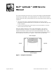
Dell™ Latitude™ L400 Service Manual This manual provides instructions for removing and replacing field-replaceable components, assemblies, and subassemblies in your Dell Latitude computer. Unless otherwise noted, each procedure in this manual assumes the following conditions: • The computer and any attached peripherals are turned off, and the peripherals are disconnected from the I/O panel on the back and right side of the computer.
Recommended Tools Most of the procedures in this manual require the use of one or more of the following tools: • #0 and #1 magnetized Phillips-head screwdrivers • Small flat-blade screwdriver • 5-mm socket wrench • Small plastic scribe • Needle-nose pliers Preparing to Work Inside Your Computer Before you start to work on the computer, perform the following steps: 1. Save any work in progress and close all open application programs. 2. Turn off the computer and any attached peripherals.
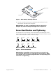
battery latch battery Figure 2. Main Battery Assembly Removal 9. Ground yourself by touching the unpainted metal surface of an I/O connector on the back of the computer. NOTICE: While you work, periodically touch the I/O panel to dissipate any static electricity that might harm components. Screw Identification and Tightening The illustrations in the following removal procedures provide lengths of the correct screws for each procedure. Figure 3 shows examples.
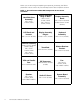
When you are removing and replacing components, photocopy the Table 1 placement mat as a tool to lay out and keep track of the component screws. Table 1. Screw Placement Mat With Component Screw Counts and Sizes Hard-Disk Drive Assembly: Display Assembly Hinge to Base: Display Assembly Bezel: M2 x 4 mm (2 each, black) M2 x 4.5 mm (2 each, silver) M2 x 3.5 mm (6 each) Rubber Screw Covers (6 each) LCD Panel and Inverter: Display Assembly Hinges: Keyboard Assembly: M2 x 3.5 mm (5 each) M2.
ZIF Connectors Some of the computer’s interface connectors are zero insertion force (ZIF) connectors. These connectors are not removable, but they must be released to disconnect a cable from them (see Figure 4). movable part of connector (do not remove) Figure 4. Disconnecting an Interface Cable NOTICE: The ZIF connectors are fragile. To avoid damage, do not apply too much pressure to the movable part of the connector. To disconnect an interface cable from a ZIF connector, perform the following steps: 1.
Removing Field-Replaceable Parts and Assemblies display assembly left hinge cover keyboard keyboard bezel right hinge cover palmrest assembly hard-disk drive audio EMI shield modem system board assembly audio I/O port cover speaker fan APR docking doors bottom case assembly main battery Figure 5.
The following subsections provide instructions for removing and replacing field-replaceable parts and assemblies. Hard-Disk Drive Assembly M3 x 3-mm screws (2) hard-disk drive bottom of computer Figure 6. Hard-Disk Drive Assembly Removal NOTICE: To avoid damaging the system board, you must remove the main battery before you service the computer. NOTICE: The hard-disk drive is very sensitive to shock.
Keyboard Bezel microphone hole keyboard bezel keyboard bezel release hole Figure 7. Keyboard Bezel Removal NOTICE: To avoid damaging the system board, you must remove the main battery before you service the computer. NOTICE: To avoid damaging the microphone, do not put any objects into the microphone hole (see Figure 7). 1. Place the point of a paper clip or a tool of similar size in the keyboard bezel hole and carefully push down (see Figure 7). 2.
Display Assembly display assembly M2 x 9.5-mm screw left hinge cover LCD flex-cable hold-down clip LCD flex cable right hinge cover M2 x 4-mm screws (2) M2 x 4.5-mm screws (2) Figure 8. Display Assembly Removal NOTICE: To avoid damaging the system board, you must remove the battery before you service the computer. 1. Remove the keyboard bezel. 2. Close the display. 3. Remove the two silver M2 x 4-mm screws at the back of the computer that secure the display assembly to the bottom case (see Figure 8).
6. Turn the computer right-side up. 7. Open the display. 8. Remove the left and right hinge covers. NOTE: When replacing the display assembly, the left hinge cover must go over the left hinge and the right hinge cover must go over the right hinge. They are not interchangeable. An L is stamped on the bottom of the left hinge cover and an R is stamped on the bottom of the right hinge cover. 9. Remove the M2 x 9.
7. Reinstall the two M2 x 4-mm screws in the back of the computer that secure the display assembly to the back of the bottom case. 8. Tighten the two screws that you installed in step 6. 9. Open the display and reinstall the left and right hinge covers. An L is stamped on the bottom of the left hinge cover and an R is stamped on the bottom of the right hinge cover. Display Assembly Bezel l large rubber screw covers (6) display assembly bezel M2 x 3.
NOTICE: To avoid damaging the system board, you must remove the main battery before you service the computer. 1. Use a scribe to carefully pry the six rubber screw covers out of the six screw holes located along the top and bottom of the bezel on the front of the display assembly (see Figure 9). 2. Remove the six M2 x 3.5-mm screws located at the top and bottom of the bezel on the front of the display assembly (see Figure 9). 3. Separate the bezel from the display-assembly top cover.
To replace the display-assembly latch, perform the following steps: 1. Carefully place the latch spring over the post on the display-assembly top cover. You may need to use a small flat-blade screwdriver to place the spring over the post. Hold the spring on the post with the screwdriver while performing the next step. 2. Holding the latch, stretch the spring slightly and set the display-assembly latch in place in the display assembly top cover. 3. Reinstall the bezel.
2. Remove the keyboard bezel. 3. Remove the display assembly. 4. Remove the display assembly bezel. 5. Remove the four M2 x 3.5-mm screws on the left and right sides of the display assembly that secure the LCD panel to the top cover (see Figure 11). 6. Remove the M2 x 3.5-mm screw that secures the inverter to the top cover. 7. Lift and roll the inverter over (toward you), so the bezel side is down and the connector side is up (see Figure 11). 8.
b. Lower the bottom end of the LCD panel into the top cover, making sure the LCD flex cable lines up with the opening that is to the right of the left hinge. c. Make sure the narrow part of the flex cable that goes to the inverter is visible at the bottom edge of the LCD panel. d. Press the LCD panel into the top cover. 5. Connect the narrow flex cable to the ZIF connector on the left side of the inverter. 6.
Keyboard Assembly M2 x 4-mm screws (4) keyboard assembly keyboard cable Figure 12. Keyboard Assembly Removal To remove the keyboard assembly, perform the following steps. NOTICE: To avoid damaging the system board, you must remove the main battery before you service the computer. NOTICE: Make sure that the work surface is clean to prevent scratching the computer cover. 1. Remove the keyboard bezel. 2. Remove the four M2 x 4-mm screws located across the top of the keyboard assembly (see Figure 9).
NOTICE: The keycaps on the keyboard are fragile, easily dislodged, and time-consuming to replace. Be careful when removing and handling the keyboard. 6. Remove the keyboard assembly. To replace the keyboard assembly, perform the following steps. NOTICE: Position the keyboard cable so it is not twisted when it is connected to the system board. 1. Connect the keyboard cable to the connector on the system board. NOTE: Five metal tabs retain the bottom of the keyboard in the palmrest assembly. 2.
Memory Module memory module inner tabs (2) Figure 13. Memory Module Removal NOTICE: To avoid damaging the system board, you must remove the main battery before you service the computer. 1. Remove the keyboard bezel. 2. Remove the keyboard assembly. 3. Ground yourself by touching the unpainted metal surface of an I/O connector on the computer’s back panel. 4.
3. Pivot the memory module down until it clicks into place. If you do not hear a click as each end of the memory module snaps into the tabs, remove the memory module and reinstall it (see Figure 13). Palmrest Assembly M2.6 x 1.6-mm screws (6) Figure 14. Removing the Palmrest Assembly Bottom Screws The palmrest assembly consists of the palmrest, status lights, and touch pad assembly. NOTICE: To avoid damaging the system board, you must remove the main battery before you service the computer. 1.
7. Remove the four black M2 x 4-mm screws across the top of the computer (see Figure 15). M2 x 6-mm screws (3 silver) M2 x 4-mm screws (4 black) touch pad flex cable palmrest assembly status lights flex cable Figure 15. Removing the Palmrest Assembly Top Screws 8. Remove the three silver M2 x 6-mm screws in the keyboard-assembly area that secure the middle of the palmrest assembly to the bottom case (see Figure 15). 9.
To replace the palmrest assembly, perform the following steps: 1. Place the palmrest assembly on the bottom assembly. 2. Reinstall the three silver M2 x 6-mm screws in the keyboard-assembly area that secure the middle of the palmrest assembly to the bottom-case assembly (see Figure 15). 3. Reinstall the four black M2 x 4-mm screws that secure the top of the palmrest assembly to the bottom-case assembly (see Figure 15). 4. Connect the touch pad flex cable to the ZIF connector on the system board. 5.
2. Remove the display assembly. 3. Remove the keyboard assembly. 4. Remove the palmrest assembly. 5. Remove the three M2 x 3.5-mm screws that secure the touch pad assembly to the palmrest assembly (see Figure 16). 6. Slide the touch pad assembly out from under the two hold-down tabs. 7. Remove the touch pad assembly from the palmrest assembly. 8. Disconnect the flex cable from the ZIF connector on the back of the touch pad (see Figure 16). The flex cable remains attached to the touch pad holder assembly.
Reserve Battery reserve battery reserve battery cable Figure 18. Reserve Battery Removal NOTICE: The reserve battery provides power to the computer's RTC and nonvolatile random-access memory (NVRAM) when the computer is turned off. Removing the battery causes the computer to lose the date and time information as well as all user-specified parameters in the BIOS. If possible, make a copy of this information before you remove the reserve battery. 1. Remove the keyboard bezel. 2.
Modem M2 x 9.5-mm screw modem modem retainer bracket Figure 19. Modem Removal 1. Remove the keyboard bezel. 2. Remove the display assembly. 3. Remove the keyboard assembly. 4. Remove the palmrest assembly. 5. Use a 5-mm socket wrench to remove the four 5-mm socket screws for the VGA and parallel ports located on the back of the bottom assembly. 6.
To replace the modem, perform the following steps: 1. Connect the modem cable to the connector on the system board. 2. Align the connector on the bottom of the modem with the connector on the system board, and carefully press the modem onto the system board. 3. Put the modem retainer bracket in place. 4. Reinstall the M2 x 9.5-mm screw to secure the modem retainer bracket and modem to the system board. 5.
4. Remove the palmrest assembly. 5. Carefully disconnect the fan wire connector from the system board (see Figure 20). The male connector on the fan wire is keyed to fit into the female connector one way only. 6. Remove the two M2 x 5-mm screws with rubber washers that secure the fan to the bottom assembly (see Figure 20). 7. Remove the fan from the bottom assembly. To replace the fan, perform the following steps: 1. Place the fan in the bottom case.
Speaker audio EMI shield M2 x 5-mm screws (2) with rubber washers EMI adhesive sponge speaker with rubber gasket speaker wire connector Figure 21. Speaker Removal 1. Remove the keyboard bezel. 2. Remove the display assembly. 3. Remove the keyboard assembly. 4. Remove the palmrest assembly. NOTICE: To ensure maximum cooling for the microprocessor, do not touch the glue side of the thermal conductive tape. The oils in your skin reduce the heat transfer capability on the glue side of the tape. 5.
NOTICE: The audio EMI shield is attached to the USB connector housing with two-sided tape. To avoid bending the audio EMI shield, care must be taken when separating the audio EMI shield from the USB connector housing. 6. Using a small flat-blade screwdriver, carefully separate the audio EMI shield away from the USB connector housing. Place the edge of the screwdriver between the audio EMI shield and the USB connector housing, and slowly pry the two apart. 7.
7. Reinstall the palmrest assembly. 8. Reinstall the keyboard assembly. 9. Reinstall the display assembly. 10. Reinstall the keyboard bezel. System Board Assembly 6 EMI adhesive sponge audio EMI shield M2 x 9.5-mm screw modem retainer bracket USB connector modem system board M2 x 3.5-mm screws (6) thermal cooling solution fan assembly fan wire connector speaker EMI clip location PC Card cover reserve battery bottom case assembly M2 x 4-mm screws (2) audio I/O port cover Figure 22.
NOTICE: To avoid damaging the system board, you must remove the main battery before you service the computer. NOTICE: The processor is not replaceable. Do not attempt to remove the thermal cooling solution. 1. Remove the keyboard bezel. 2. Remove the display assembly. 3. Remove the keyboard. 4. Remove the palmrest assembly. 5. Use a 5-mm socket wrench to remove the four 5-mm socket screws for the VGA and parallel ports located on the back of the bottom case assembly. 6.
13. Remove the modem retainer bracket from the bottom case assembly. 14. Disconnect the speaker wire from the connector on the system board assembly. 15. Disconnect the fan wire from the connector on the system board assembly. 16. Lift the system board assembly out of the bottom case assembly. To replace the system board assembly, perform the following steps: 1. Transfer the memory module(s) to the replacement system board assembly. 2.
One of the M2 x 3.5-mm screws passes through the hard-disk drive EMI clip (see Figure 23). 9. Reinstall the audio EMI shield. a. Carefully position the audio EMI shield so the section with the two-sided tape is over the USB connector housing. b. Press the audio EMI shield down so it attaches to the USB connector housing. c. Reattach the EMI adhesive sponge across the thermal cooling solution. 10.
1. Remove the keyboard bezel. 2. Remove the display assembly. 3. Remove the keyboard. 4. Remove the palmrest assembly. 5. Remove the system board. NOTICE: The tabs on the release button are plastic. Care should be taken when squeezing the tabs to avoid breaking them. 6. Using needle-nose pliers, gently squeeze the two tabs on the back of the release button together and grasp the top of the battery release latch and gently pull up to free it from the release button assembly (see Figure 24). 7.
To replace the APR docking doors, perform the following steps. NOTE: On the under side of the doors, a small F is printed on the front door and a small B is printed on the back door. As you hold the doors for installation, the front door is near you, the back door is away from you, and the tension spring is to the left. 1. Turn the computer upside down. The APR connector door opening should be at the top. 2.
Index A H APR docking doors removal, 33 hard-disk drive assembly removal, 7 hinge removal, 15 B bottom assembly components, 22 illustrated, 22 D display assembly bezel removal, 11 hinge removal, 15 latch removal, 12 removal, 9 K keyboard assembly removal, 16 L latch removal, 12 LCD panel removal, 13 M F main battery release latch removal, 32 removal, 3, 23 fan removal, 25 memory module removal, 18 field-replaceable parts and assemblies illustrated, 6 modem removal, 24 G P palmrest assembly
R T reserve battery removal, 23 tools, 2 touch pad removal, 21 S screw identification and tightening, 3 Z speaker removal, 27 ZIF connectors, 5 system board assembly removal, 29 2 Dell Latitude L400 Service Manual
Printed in the U.S.A. 067CUJ A00 P/N 67CUJ Rev.