
User Guide


vi
Figure 6. Hard-Disk Drive Assembly Removal . . . . . . . . . . . . . . . . . . . . . . . 7
Figure 7. Keyboard Bezel Removal . . . . . . . . . . . . . . . . . . . . . . . . . . . . . . . . 8
Figure 8. Display Assembly Removal . . . . . . . . . . . . . . . . . . . . . . . . . . . . . . 9
Figure 9. Display Assembly Bezel Removal . . . . . . . . . . . . . . . . . . . . . . . . 11
Figure 10. Display Assembly Latch Removal . . . . . . . . . . . . . . . . . . . . . . . . 12
Figure 11. LCD Panel Removal . . . . . . . . . . . . . . . . . . . . . . . . . . . . . . . . . . . 13
Figure 12. Keyboard Assembly Removal . . . . . . . . . . . . . . . . . . . . . . . . . . . 16
Figure 13. Memory Module Removal . . . . . . . . . . . . . . . . . . . . . . . . . . . . . . 18
Figure 14. Removing the Palmrest Assembly Bottom Screws. . . . . . . . . . . 19
Figure 15. Removing the Palmrest Assembly Top Screws. . . . . . . . . . . . . . 20
Figure 16. Touch Pad Removal . . . . . . . . . . . . . . . . . . . . . . . . . . . . . . . . . . . 21
Figure 17. Bottom Assembly . . . . . . . . . . . . . . . . . . . . . . . . . . . . . . . . . . . 22
Figure 18. Reserve Battery Removal . . . . . . . . . . . . . . . . . . . . . . . . . . . . . . 23
Figure 19. Modem Removal . . . . . . . . . . . . . . . . . . . . . . . . . . . . . . . . . . . . . 24
Figure 20. Fan Removal . . . . . . . . . . . . . . . . . . . . . . . . . . . . . . . . . . . . . . . . 25
Figure 21. Speaker Removal . . . . . . . . . . . . . . . . . . . . . . . . . . . . . . . . . . . . . 27
Figure 22. System Board Assembly Removal. . . . . . . . . . . . . . . . . . . . . . . . 29
Figure 23. Hard-Disk Drive EMI Clip . . . . . . . . . . . . . . . . . . . . . . . . . . . . . . . 31
Figure 24. Main Battery Release Latch Removal . . . . . . . . . . . . . . . . . . . . . 32
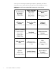
Tables Table 1. Screw Placement Mat With Component Screw Counts
and Sizes . . . . . . . . . . . . . . . . . . . . . . . . . . . . . . . . . . . . . . . . . . . . 4