
User Guide


4 Dell Latitude L400 Service Manual
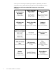
When you are removing and replacing components, photocopy the Table 1
placement mat as a tool to lay out and keep track of the component screws.
Table 1. Screw Placement Mat With Component Screw Counts
and Sizes
Hard-Disk Drive
Assembly:
M3 x 3 mm
(2 each, black)
Display Assembly
Hinge to Base:
M2 x 4 mm
(2 each, black)
M2 x 4.5 mm
(2 each, silver)
Display Assembly
Bezel:
M2 x 3.5 mm (6 each)
Rubber Screw Covers
(6 each)
LCD Panel and
Inverter:
M2 x 3.5 mm (5 each)
Display Assembly
Hinges:
M2.6 x 4 mm (4 each)
Keyboard
Assembly:
M2 x 4 mm (4 each)
Palmrest Assembly:
M2.6 x 1.6 mm (6 each
[battery bay])
M2 x 4 mm
(4 each, black)
M2 x 6 mm
(3 each, silver)
Touch Pad:
M2 x 3.5 mm (3 each)
Modem Retainer
Bracket:
M2 x 9.5 mm (2 each)
VGA and Parallel
Port:
5 mm socket (4 each)
IDE Connector:
IDE connector screws
(2 each)
Fan:
M2 x 8 mm
(2 each, silver,
with 2 rubber washers
each)
Speaker:
M2 x 5 mm
(2 each, silver,
with rubber washer)
Audio I/O Cover:
M2 x 4 mm (2 each)
System Board
Assembly:
M2 x 3.5 mm (6 each)