Dell Latitude V710/V740 Service Manual Dell™ Latitude™ V710/V740 Service Manual Before You Begin Preparing to Work Inside the Computer Recommended Tools Computer Orientation Screw Identification System Components Back-Panel Fan (V740 Only) Hard Drive Memory Module, Modem, Optical Drive, and Floppy Drive Memory Module Modem Optical Drive Floppy Drive Keyboard Display Assembly and Display Latch Display Assembly Display Latch EMI Shield, Video Board, and Palm Rest EMI Shield Video Board Palm Rest Microprocess
Dell Latitude V710/V740 Service Manual Parallel Connector Notes, Notices, and Cautions NOTE: A NOTE indicates important information that helps you make better use of your computer. NOTICE: A NOTICE indicates either potential damage to hardware or loss of data and tells you how to avoid the problem. CAUTION: A CAUTION indicates a potential for property damage, personal injury, or death.
Before You Begin: Dell Latitude V710/V740 Service Manual Back to Contents Page Before You Begin Dell™ Latitude™ V710/V740 Service Manual Preparing to Work Inside the Computer Recommended Tools Computer Orientation Screw Identification Preparing to Work Inside the Computer CAUTION: Only a certified service technician should perform repairs on your computer. Damage due to servicing that is not authorized by Dell is not covered by your warranty.
Before You Begin: Dell Latitude V710/V740 Service Manual disconnect any attached devices. 6. Disconnect all other external cables from the computer. 7. Remove any installed PC Cards from the PC Card slot. 8. Close the display and turn the computer upside down on a flat work surface. NOTICE: To avoid damaging the system board, you must remove the main battery before you service the computer.
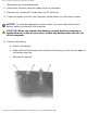
Before You Begin: Dell Latitude V710/V740 Service Manual 1 battery lock 2 battery latch release 3 battery 10. To dissipate any static electricity while you work, use a wrist grounding strap or periodically touch an unpainted metal surface. 11. Handle components and cards with care. Do not touch the components or contacts on a card. Hold a card by its edges or by its metal mounting bracket. Hold a component such as a microprocessor by its edges, not by its pins.
Before You Begin: Dell Latitude V710/V740 Service Manual 1 back 2 right 3 front 4 left Screw Identification When you are removing and replacing components, photocopy "Screw Identification" as a tool to lay out and keep track of the screws. The placemat provides the number of screws and their sizes. file:///F|/Service%20Manuals/Dell/Latitude/v710-740/begin.
Before You Begin: Dell Latitude V710/V740 Service Manual NOTICE: When reinstalling a screw, you must use a screw of the correct diameter and length. Ensure that the screw is properly aligned with its corresponding hole, and avoid overtightening. NOTE: All M2.5 x 4 screws are silver, and all other screws are black.
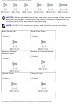
Before You Begin: Dell Latitude V710/V740 Service Manual Keyboard Assembly to Hinges: Keyboard to Bottom Case: (2 each) (4 each; silver screws) Display Assembly to Back Panel: Display-Feed Flex Cable to System Board: (2 each) (2 each) Hinge Bracket to Bottom Case: Display Bezel: (4 each) (5 each) Screw Covers (5 each) file:///F|/Service%20Manuals/Dell/Latitude/v710-740/begin.
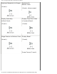
Before You Begin: Dell Latitude V710/V740 Service Manual Display Panel: (4 each) Display-Feed Flex Cable to Display Assembly: (1 each) Display Latch: EMI Shield: (2 each) (3 each) Top of Palm Rest to Bottom Case: Video Board to Bottom Case: (2 each) (1 each) Palm Rest to Bottom Case: Floppy Drive Cage to Bottom Case: (12 each) (2 each) file:///F|/Service%20Manuals/Dell/Latitude/v710-740/begin.
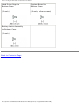
Before You Begin: Dell Latitude V710/V740 Service Manual Hard Drive Cage to Bottom Case: System Board to Bottom Case: (2 each) (6 each; silver screws) Battery Latch Assembly to Bottom Case: (1 each) Back to Contents Page file:///F|/Service%20Manuals/Dell/Latitude/v710-740/begin.
System Components: Dell Latitude V710/V740 Service Manual Back to Contents Page System Components Dell™ Latitude™ V710/V740 Service Manual NOTICE: Only a certified service technician should perform repairs on your computer. Damage due to servicing that is not authorized by Dell is not covered by your warranty. NOTICE: Unless otherwise noted, each procedure in this document assumes that a part can be replaced by performing the removal procedure in reverse order.
System Components: Dell Latitude V710/V740 Service Manual 1 display assembly 13 hard drive 2 display-feed flex cable 14 hard drive cage 3 center control cover 15 floppy drive cage 4 keyboard 16 floppy drive 5 video board 17 speaker 6 microprocessor 18 modem 7 system board 19 microprocessor thermalcooling assembly 8 battery connector cover 20 headphone/microphone bridge 9 optical drive 21 palm rest 10 back-panel fan (V740 only) 22 memory module/modem cover 11 bottom case 23 EMI
System Components: Dell Latitude V710/V740 Service Manual file:///F|/Service%20Manuals/Dell/Latitude/v710-740/system.
Back-Panel Fan (V740 Only): Dell Latitude V710/V740 Service Manual Back to Contents Page Back-Panel Fan (V740 Only) Dell™ Latitude™ V710/V740 Service Manual Removing the Back-Panel Fan NOTICE: To prevent data loss, turn off the computer before removing the backpanel fan. Do not remove the fan while the computer is on or in a power management mode. NOTICE: Read "Preparing to Work Inside the Computer" before performing the following procedure. 1.
Back-Panel Fan (V740 Only): Dell Latitude V710/V740 Service Manual 1 M2.5 x 5-mm screws (2) 2 fan cover 3 scalloped left edge of fan cover 4. Use a small flat-blade screwdriver or plastic scribe to lift the scalloped left edge of the fan cover, and pry the cover loose from the bottom case. 5. Lift the fan cover up and away from the bottom case. 6. Disconnect the fan cable connector from the system board. 7. Lift the fan out of the bottom case. file:///F|/Service%20Manuals/Dell/Latitude/v710-740/fan.
Back-Panel Fan (V740 Only): Dell Latitude V710/V740 Service Manual 1 fan 2 fan cable connector Replacing the Back-Panel Fan 1. Slide the fan into the bottom case. 2. Tuck the fan cable under the bottom case, and connect the cable to the system board. file:///F|/Service%20Manuals/Dell/Latitude/v710-740/fan.
Back-Panel Fan (V740 Only): Dell Latitude V710/V740 Service Manual 1 fan cable 3. Replace the fan cover, and reinstall the two M2.5 x 5-mm screws that secure the cover to the bottom case. Back to Contents Page file:///F|/Service%20Manuals/Dell/Latitude/v710-740/fan.
Hard Drive: Dell Latitude V710/V740 Service Manual Back to Contents Page Hard Drive Dell™ Latitude™ V710/V740 Service Manual Removing the Hard Drive NOTICE: To prevent data loss, turn off the computer before removing the hard drive. Do not remove the hard drive while the computer is on or in a power management mode. NOTICE: Hard drives are extremely fragile; even a slight bump can damage the drive.
Hard Drive: Dell Latitude V710/V740 Service Manual NOTICE: When the hard drive is not in the computer, store it in protective antistatic packaging. 1 bottom of computer 2 M2.5 x 5-mm screw 3 hard drive door 4. Lift the hard drive door to release it, and slide the hard drive out of the computer. Replacing the Hard Drive 1. Remove the new drive from its packaging. Save the original packaging to use when storing or shipping the hard drive. file:///F|/Service%20Manuals/Dell/Latitude/v710-740/hdd.
Hard Drive: Dell Latitude V710/V740 Service Manual NOTICE: Use firm and even pressure to slide the drive into place. If you force the hard drive into place using excessive force, you may damage the connector. 2. Slide the hard drive into the bay, and press down on the hard drive door until it is fully seated. 3. Replace and tighten the M2.5 x 5-mm screw in the hard drive door. 4. Use the Operating System CD to install the operating system for your computer. 5.
Memory Module, Modem, Optical Drive, and Floppy Drive: Dell Latitude V710/V740 Service Manual Back to Contents Page Memory Module, Modem, Optical Drive, and Floppy Drive Dell™ Latitude™ V710/V740 Service Manual Memory Module Modem Optical Drive Floppy Drive Memory Module Removing the Memory Module/Modem Cover NOTE: This procedure covers removing and replacing the memory module located under the memory module/modem cover on the bottom of the computer.
Memory Module, Modem, Optical Drive, and Floppy Drive: Dell Latitude V710/V740 Service Manual b. Slide the cover out approximately 10 mm, and lift it away from the computer. 1 M2.5 x 5-mm screw 2 memory module/modem cover NOTICE: To prevent damage to the memory module connector, do not use tools to spread the inner metal tabs that secure the memory module. 2. If you are replacing a memory module, remove the existing module.
Memory Module, Modem, Optical Drive, and Floppy Drive: Dell Latitude V710/V740 Service Manual b. Remove the module from the connector. 1 securing clip 2 memory module 3. Ground yourself and install the new memory module: a. Align the notch in the module with the slot in the center of the connector. b. Slide the edge of the module firmly into the connector, and rotate the module down until you hear a click. If you do not hear the click, remove the module and reinstall it.
Memory Module, Modem, Optical Drive, and Floppy Drive: Dell Latitude V710/V740 Service Manual 4. Replace the cover and screw: a. Place the memory module/modem cover over the memory module/modem compartment so that the end of the cover with the screw hole is lined up with the lines and arrows on the bottom of the computer. b. Press down on the center of the memory module/modem cover, and slide the cover until it is secured. c. Replace and tighten the M2.5 x 5-mm screw.
Memory Module, Modem, Optical Drive, and Floppy Drive: Dell Latitude V710/V740 Service Manual 1 M2.5 x 5-mm screw 2 memory module/modem cover 3 arrows (2) 4 lines (2) 5. Insert the battery into the battery bay, or connect the AC adapter to your computer and an electrical outlet. 6. Turn on the computer. As the computer boots, it detects the additional memory and automatically updates the system configuration information. Modem file:///F|/Service%20Manuals/Dell/Latitude/v710-740/upgrades.
Memory Module, Modem, Optical Drive, and Floppy Drive: Dell Latitude V710/V740 Service Manual CAUTION: Before performing these procedures, turn off the computer, disconnect it from the electrical outlet, and disconnect the modem from the telephone wall jack. NOTICE: Disconnect any attached devices from electrical outlets, and remove any installed batteries. NOTICE: To avoid ESD, ground yourself by using a wrist grounding strap or by touching an unpainted metal surface on the computer.
Memory Module, Modem, Optical Drive, and Floppy Drive: Dell Latitude V710/V740 Service Manual 2. If a modem is not already installed, go to step 3. If you are replacing a modem, remove the existing modem: a. Remove the two M2 x 3-mm screws that secure the modem to the system board, and set them aside. b. Pull the modem straight up by the pull tab to lift the modem out of its connector, and disconnect the modem cable. 1 M2 x 3-mm screws (2) 2 pull tab 3 modem cable connector 4 modem cable 3.
Memory Module, Modem, Optical Drive, and Floppy Drive: Dell Latitude V710/V740 Service Manual NOTICE: The cable connectors are keyed for correct insertion; do not force the connections. 4. Align the modem with the screw holes and press the modem into its connector on the system board. Install the two M2 x 3-mm screws to secure the modem to the system board. 5. Replace the memory module/modem cover and screw: a.
Memory Module, Modem, Optical Drive, and Floppy Drive: Dell Latitude V710/V740 Service Manual 1 M2.5 x 5-mm screw 2 memory module/modem cover 3 arrows (2) 4 lines (2) Optical Drive Removing an Installed Optical Drive NOTICE: To avoid ESD, ground yourself by using a wrist grounding strap or by touching an unpainted metal surface on the computer. NOTICE: Read "Preparing to Work Inside the Computer" before performing the following procedure. file:///F|/Service%20Manuals/Dell/Latitude/v710-740/upgrades.
Memory Module, Modem, Optical Drive, and Floppy Drive: Dell Latitude V710/V740 Service Manual 1. If a disc is in the optical drive, remove the disc. NOTICE: Disconnect the computer and attached devices from electrical outlets, and remove any installed batteries. 2. Remove the memory module/modem cover: a. Remove the M2.5 x 5-mm screw from the memory module/modem cover. b. Slide the cover out approximately 10 mm, and lift it away from the computer. 1 M2.5 x 5-mm screw 2 memory module/modem cover 3.
Memory Module, Modem, Optical Drive, and Floppy Drive: Dell Latitude V710/V740 Service Manual 1 M2.5 x 8-mm screw 2 optical-drive release button 3 optical drive Installing an Optical Drive 1. Slide the optical drive into the bay until the optical drive is fully seated. 2. Replace and tighten the M2.5 x 8-mm screw. file:///F|/Service%20Manuals/Dell/Latitude/v710-740/upgrades.
Memory Module, Modem, Optical Drive, and Floppy Drive: Dell Latitude V710/V740 Service Manual 1 M2.5 x 8-mm screw 2 optical drive NOTICE: Replace the memory module/modem cover so that it is seated properly around the edges and does not bulge near the center of the cover. Tightening the memory-module/modem cover screw when the cover is improperly seated can damage your computer. 3. Replace the memory module/modem cover and screw: a.
Memory Module, Modem, Optical Drive, and Floppy Drive: Dell Latitude V710/V740 Service Manual 1 M2.5 x 5-mm screw 2 memory module/modem cover 3 arrows (2) 4 lines (2) Floppy Drive Removing an Installed Floppy Drive NOTICE: To avoid ESD, ground yourself by using a wrist grounding strap or by touching an unpainted metal surface on the computer. NOTICE: Read "Preparing to Work Inside the Computer" before performing the following procedure. 1. If a disk is in the floppy drive, remove the disk.
Memory Module, Modem, Optical Drive, and Floppy Drive: Dell Latitude V710/V740 Service Manual NOTICE: Disconnect the computer and attached devices from electrical outlets, and remove any installed batteries. NOTICE: Ensure that you disconnect the flex cable from the ZIF connector before you remove the floppy drive from the computer. See step 3 for further instructions. 2. Remove the two M2.5 x 5-mm screws from the floppy drive, and partially pull the drive out of the computer. 1 M2.
Memory Module, Modem, Optical Drive, and Floppy Drive: Dell Latitude V710/V740 Service Manual NOTICE: Release the securing tab before you disconnect the flex cable from the ZIF connector. Failure to do so can damage the ZIF connector. 3. Disconnect the flex cable from the ZIF connector: a. Pull the securing tab away from the ZIF connector. b. Gently pull the flex cable out of the ZIF connector. 1 ZIF connector 2 securing tab 3 flex cable Installing a Floppy Drive 1.
Memory Module, Modem, Optical Drive, and Floppy Drive: Dell Latitude V710/V740 Service Manual NOTE: If you do not connect the flex cable to the ZIF connector properly, your floppy drive will not function properly. 2. Reconnect the flex cable to the ZIF connector: a. Pull and hold the securing tab away from the ZIF connector. b. While holding the securing tab, insert the flex cable into the ZIF connector. Ensure that you insert the flex cable into the ZIF connector and not below the ZIF connector. c.
Memory Module, Modem, Optical Drive, and Floppy Drive: Dell Latitude V710/V740 Service Manual 1 ZIF connector 2 securing tab 3 flex cable 3. Slide the floppy drive into the bay until the drive is fully seated. 4. Replace and tighten the two M2.5 x 5-mm screws. 5. Install the battery. 6. Turn on the computer and try using the floppy drive. If the computer does not detect the floppy drive, you may have improperly inserted the flex cable.
Memory Module, Modem, Optical Drive, and Floppy Drive: Dell Latitude V710/V740 Service Manual Back to Contents Page file:///F|/Service%20Manuals/Dell/Latitude/v710-740/upgrades.
Keyboard: Dell Latitude V710/V740 Service Manual Back to Contents Page Keyboard Dell™ Latitude™ V710/V740 Service Manual Removing the Keyboard NOTICE: Disconnect the computer and any attached devices from electrical outlets, and remove any installed batteries. NOTICE: To avoid ESD, ground yourself by using a wrist grounding strap or by touching an unpainted metal surface on the computer. NOTICE: Read "Preparing to Work Inside the Computer" before performing the following procedure. 1.
Keyboard: Dell Latitude V710/V740 Service Manual 1 M2.5 x 5-mm screws (2) b. Open the display assembly at an angle of approximately 180 degrees and support the display assembly so that it does not open past this position. c. Use a small flat-blade screwdriver or plastic scribe to lift the scalloped right edge of the center control cover and pry the cover loose from the hinges and bottom case. d. Lift the center control cover up and away from the hinges and bottom case.
Keyboard: Dell Latitude V710/V740 Service Manual NOTE: The M2.5 x 4 screws are silver. 2. Remove the four M2.5 x 4-mm screws across the top of the keyboard. 1 M2.5 x 4-mm screws (4) 2 scalloped edge of blank key 3 keyboard 4 palm rest NOTICE: The keycaps on the keyboard are fragile, easily dislodged, and timeconsuming to replace. Be careful when removing and handling the keyboard. 3. Lift the keyboard straight up until it clears the top of the bottom case. 4.
Keyboard: Dell Latitude V710/V740 Service Manual NOTICE: Do not pull on the keyboard flex cable. 6. Pull up on the keyboard connector to disconnect it from the interface connector on the system board. 1 keyboard securing tabs (4) 2 keyboard flex cable 3 keyboard connector 4 interface connector on system board 7. Remove the keyboard from the bottom case. file:///F|/Service%20Manuals/Dell/Latitude/v710-740/keyboard.
Keyboard: Dell Latitude V710/V740 Service Manual Replacing the Keyboard NOTICE: The keycaps on the keyboard are fragile, easily dislodged, and timeconsuming to replace. Be careful when handling and replacing the keyboard. 1. Place the keyboard on the palm rest at the front of the computer with the keys face down and the connector toward the back of the computer.
Keyboard: Dell Latitude V710/V740 Service Manual NOTE: The M2.5 x 4 screws are silver. 5. Replace the four M2.5 x 4-mm screws at the top of the keyboard. 6. Replace the center control cover. Ensure that the center control cover is snapped in properly so that it is flush with the keyboard. 7. Replace the two M2.5 x 5-mm screws in the back of the hinges. Back to Contents Page file:///F|/Service%20Manuals/Dell/Latitude/v710-740/keyboard.
Display Assembly and Display Latch: Dell Latitude V710/V740 Service Manual Back to Contents Page Display Assembly and Display Latch Dell™ Latitude™ V710/V740 Service Manual Display Assembly Display Latch Display Assembly NOTICE: You must remove the display assembly before you remove the palm rest. NOTICE: Disconnect the computer and any attached devices from electrical outlets, and remove any installed batteries.
Display Assembly and Display Latch: Dell Latitude V710/V740 Service Manual 1 top cover 2 M2.5 x 5-mm screws (2) 3 bottom case 1. Remove the keyboard. 2. Close the display assembly. 3. From the back of the computer, remove the two M2.5 x 5-mm screws labeled "circle D." 4. Open the display assembly approximately 180 degrees and support the display assembly so that it does not open past this position. 5. Remove the two M2.5 x 5-mm screws that secure the display-feed flex cable to the system board.
Display Assembly and Display Latch: Dell Latitude V710/V740 Service Manual 1 M2.5 x 5-mm screws (4) 2 hinge blocks (2) 3 M2.5 x 5-mm screws (2) 4 display-feed flex cable 5 pull tab 6. Pull up on the pull tab that is attached to the display-feed flex cable connector to remove the connector from the system board. 7. Remove the two M2.5 x 5-mm screws from each hinge block. file:///F|/Service%20Manuals/Dell/Latitude/v710-740/display.
Display Assembly and Display Latch: Dell Latitude V710/V740 Service Manual 8. Lift the display assembly up and out of the bottom case. file:///F|/Service%20Manuals/Dell/Latitude/v710-740/display.
Display Assembly and Display Latch: Dell Latitude V710/V740 Service Manual 1 screw covers (5) 6 M2 x 3-mm screws (4) 2 M2.5 x 5-mm screws (5) 7 M2.5 x 5-mm screw (1) 3 display bezel 8 display-feed flex cable 4 display panel 9 flex-cable retention bracket 5 M2.5 x 5-mm screws (2) 10 top cover Removing the Display Bezel NOTICE: Disconnect the computer and any attached devices from electrical outlets, and remove any installed batteries.
Display Assembly and Display Latch: Dell Latitude V710/V740 Service Manual NOTICE: To avoid ESD, ground yourself by using a wrist grounding strap or by touching an unpainted metal surface on the computer. NOTICE: Read "Preparing to Work Inside the Computer" before performing the following procedure. 1. Remove the keyboard. 2. Remove the display assembly. 3. Remove the display bezel. 4. Remove the two M2 x 3-mm screws on the left side of the display panel. 5.
Display Assembly and Display Latch: Dell Latitude V710/V740 Service Manual 9. Disconnect the bottom flex cable connector from the inverter connector on the system board by pulling on the attached pull tab away from the inverter connector. 1 top flex cable connector 2 display panel connector 3 pull tab 4 pull tab 5 inverter connector on system board file:///F|/Service%20Manuals/Dell/Latitude/v710-740/display.
Display Assembly and Display Latch: Dell Latitude V710/V740 Service Manual 6 bottom flex cable connector 10. Remove the tape that secures the display panel connector and the tape that secures the middle of the display-feed flex cable to the display panel. 11. Pull the top flex cable connector down and away to remove it from the display panel connector. Replacing the Display Panel 1. Reconnect the top flex cable connector to the display panel connector. 2.
Display Assembly and Display Latch: Dell Latitude V710/V740 Service Manual 3. Remove the display bezel. 4. Remove the two M2.5 x 5-mm screws that secure the display latch and bracket to the top cover. 5. Lift the display latch, bracket, and spring up and out of the top cover. 1 spring 2 spring hook (display latch) 3 M2.5 x 5-mm screws (2) 4 display latch 5 bracket 6 spring hook (top cover) Replacing the Display Latch 1.
Display Assembly and Display Latch: Dell Latitude V710/V740 Service Manual 3. Replace the two M2.5 x 5-mm screws that secure the display latch and bracket to the top cover. Back to Contents Page file:///F|/Service%20Manuals/Dell/Latitude/v710-740/display.
EMI Shield, Video Board, and Palm Rest: Dell Latitude V710/V740 Service Manual Back to Contents Page EMI Shield, Video Board, and Palm Rest Dell™ Latitude™ V710/V740 Service Manual EMI Shield Video Board Palm Rest EMI Shield NOTICE: Disconnect the computer and any attached devices from electrical outlets, and remove any installed batteries. NOTICE: To avoid ESD, ground yourself by using a wrist grounding strap or by touching an unpainted metal surface on the computer.
EMI Shield, Video Board, and Palm Rest: Dell Latitude V710/V740 Service Manual 1 EMI shield 2 M2.5 x 12-mm screws (3) Video Board Removing the Video Board NOTICE: Disconnect the computer and any attached devices from electrical outlets, and remove any installed batteries. NOTICE: To avoid ESD, ground yourself by using a wrist grounding strap or by touching an unpainted metal surface on the computer. NOTICE: Read "Preparing to Work Inside the Computer" before performing the following procedure. 1.
EMI Shield, Video Board, and Palm Rest: Dell Latitude V710/V740 Service Manual ● For V710, the screw is M2.5 x 5 mm. ● For V740, the screw is M2.5 x 8mm. 4. Pull the video board out of the bottom case: ● For V710, pull the video board by the edges toward the front of the computer. ● For V740, pull the video board by the pull tab toward the front of the computer. V710 Video Board 1 M2.
EMI Shield, Video Board, and Palm Rest: Dell Latitude V710/V740 Service Manual 1 V740 video board 2 M2.5 x 8-mm screw (1) 3 pull tab Replacing the Video Board 1. Align the top right corner of the video board with the guide on the system board, and slide the top edge of the video board under the palm rest. V710 Video Board file:///F|/Service%20Manuals/Dell/Latitude/v710-740/palmrest.
EMI Shield, Video Board, and Palm Rest: Dell Latitude V710/V740 Service Manual 1 M2.5 x 5-mm screw (1) 2 palm rest 3 top right corner of the V710 video board 4 guide V740 Video Board file:///F|/Service%20Manuals/Dell/Latitude/v710-740/palmrest.
EMI Shield, Video Board, and Palm Rest: Dell Latitude V710/V740 Service Manual 1 M2.5 x 8-mm screw (1) 2 palm rest 3 top right corner of the V740 video board 4 guide NOTICE: For V740 only, before you connect the video board to the system board, ensure that you route the power- board flex cable under the memory module. 2. Lay the video board flat on the system board, and connect the video board connector to the interface connector on the system board.
EMI Shield, Video Board, and Palm Rest: Dell Latitude V710/V740 Service Manual 1 bottom of V710 video board 2 video board connector 3 system board 4 interface connector NOTICE: For V740 only, before you connect the video board to the system board, ensure that you route the power- board flex cable under the memory module. V740 Video Board Connector file:///F|/Service%20Manuals/Dell/Latitude/v710-740/palmrest.
EMI Shield, Video Board, and Palm Rest: Dell Latitude V710/V740 Service Manual 1 bottom of V740 video board 2 video board connector 3 system board 4 interface connector 5 power-board flex cable 6 memory module 3. Reinstall the screw that secures the video board to the bottom case: ● For V710, reinstall the M2.5 x 5-mm screw. ● For V740, reinstall the M2.5 x 8-mm screw. 4. Replace the EMI Shield. file:///F|/Service%20Manuals/Dell/Latitude/v710-740/palmrest.
EMI Shield, Video Board, and Palm Rest: Dell Latitude V710/V740 Service Manual 5. Replace the keyboard. Palm Rest NOTICE: Disconnect the computer and any attached devices from electrical outlets, and remove any installed batteries. NOTICE: To avoid ESD, ground yourself by using a wrist grounding strap or by touching an unpainted metal surface on the computer. NOTICE: Read "Preparing to Work Inside the Computer" before performing the following procedure. 1. Remove the keyboard.
EMI Shield, Video Board, and Palm Rest: Dell Latitude V710/V740 Service Manual 1 M2.5 x 5-mm screws (2) 2 top of the palm rest 6. Turn the computer over and remove the twelve M2.5 x 8-mm screws labeled "circle P." file:///F|/Service%20Manuals/Dell/Latitude/v710-740/palmrest.
EMI Shield, Video Board, and Palm Rest: Dell Latitude V710/V740 Service Manual 1 M2.5 x 8-mm screws (12) 7. Turn the computer over, and disconnect the touch pad connector and power board connector from the system board. file:///F|/Service%20Manuals/Dell/Latitude/v710-740/palmrest.
EMI Shield, Video Board, and Palm Rest: Dell Latitude V710/V740 Service Manual 1 back center of the palm rest 2 touch pad connector 3 power board connector NOTICE: Carefully separate the palm rest from the bottom case to avoid damage to the palm rest. 8. Starting at the back center of the palm rest, use your fingers to separate the palm rest from the bottom case by lifting the inside of the palm rest while pushing in on the outside.
Microprocessor Thermal-Cooling Assembly: Dell Latitude V710/V740 Service Manual Back to Contents Page Microprocessor Thermal-Cooling Assembly Dell™ Latitude™ V710/V740 Service Manual Removing the Microprocessor Thermal-Cooling Assembly NOTICE: Disconnect the computer and any attached devices from electrical outlets, and remove any installed batteries. NOTICE: To avoid ESD, ground yourself by using a wrist grounding strap or by touching an unpainted metal surface on the computer.
Microprocessor Thermal-Cooling Assembly: Dell Latitude V710/V740 Service Manual 1 microprocessor thermalcooling assembly 2 captive screws (4) 3 fan power cable 5. Lift the microprocessor thermal-cooling assembly up toward the front of the computer and out of the system board. Replacing the Microprocessor Thermal-Cooling Assembly 1. Place the back of the microprocessor thermal-cooling assembly under the palm rest and lower the assembly onto the system board. 2.
Microprocessor Thermal-Cooling Assembly: Dell Latitude V710/V740 Service Manual file:///F|/Service%20Manuals/Dell/Latitude/v710-740/thermal.
Microprocessor Module: Dell Latitude V710/V740 Service Manual Back to Contents Page Microprocessor Module Dell™ Latitude™ V710/V740 Service Manual Removing the Microprocessor Module NOTICE: Disconnect the computer and any attached devices from electrical outlets, and remove any installed batteries. NOTICE: To avoid ESD, ground yourself by using a wrist grounding strap or by touching an unpainted metal surface on the computer.
Microprocessor Module: Dell Latitude V710/V740 Service Manual 1 screwdriver (perpendicular to microprocessor) 2 pin-1 corner 3 processor die (do not touch) 4 ZIF socket 5 ZIF-socket cam screw 1. Remove the keyboard. 2. Remove the EMI Shield. file:///F|/Service%20Manuals/Dell/Latitude/v710-740/cpu.
Microprocessor Module: Dell Latitude V710/V740 Service Manual NOTICE: To ensure maximum cooling for the microprocessor, do not touch the heat transfer areas on the microprocessor thermal-cooling assembly. The oils in your skin reduce the heat transfer capability of the thermal pads. 3. Remove the microprocessor thermal-cooling assembly. NOTICE: When removing the microprocessor module, pull the module straight up. Be careful not to bend the pins on the microprocessor module. 4.
Microprocessor Module: Dell Latitude V710/V740 Service Manual When the microprocessor module is correctly seated, all four corners are aligned at the same height. If one or more corners of the module are higher than the others, the module is not seated correctly. NOTICE: Hold the microprocessor down while turning the cam screw to prevent intermittent contact between the cam screw and microprocessor. 2.
Flashing the BIOS: Dell Latitude V710/V740 Service Manual Back to Contents Page Flashing the BIOS Dell™ Latitude™ V710/V740 Service Manual 1. Ensure that the AC adapter is plugged in and that the main battery is installed properly. 2. Turn on the computer. Follow the instructions that appear on the screen. The computer continues to boot and updates the new BIOS. When the flash update is complete, the computer will automatically reboot. 3. Press during POST to enter the system setup program. 4.
Speakers: Dell Latitude V710/V740 Service Manual Back to Contents Page Speakers Dell™ Latitude™ V710/V740 Service Manual Removing the Speakers NOTICE: Disconnect the computer and any attached devices from electrical outlets, and remove any installed batteries. NOTICE: To avoid ESD, ground yourself by using a wrist grounding strap or by touching an unpainted metal surface on the computer. NOTICE: Read "Preparing to Work Inside the Computer" before performing the following procedure.
Speakers: Dell Latitude V710/V740 Service Manual 1 speaker connector 7 hard drive cage 2 routing clips (10) 8 left speaker cable 3 battery bay 9 left die casting 4 right speaker 10 left speaker 5 right speaker cable 11 floppy drive cage 6 right die casting 1. Remove the hard drive. 2. Remove the floppy drive. 3. Remove the keyboard. 4. Remove the display assembly. 5. Remove the EMI Shield. 6. Remove the video board. file:///F|/Service%20Manuals/Dell/Latitude/v710-740/speakers.
Speakers: Dell Latitude V710/V740 Service Manual 7. Remove the palm rest. 8. Disconnect the speaker connector from the system board. NOTICE: Remove the speaker cables from their routing clips and die casting with care to avoid damaging the cables. 9. Remove the speaker cables from under or between their routing clips and die casting. NOTICE: Handle the speakers with care to avoid damaging them. 10. Remove the speakers by pulling them straight up and out of the bottom case.
Speakers: Dell Latitude V710/V740 Service Manual NOTE: The right speaker cable is longer than the left speaker cable. NOTE: Speakers face out in the bottom case holders. 1. Slide the speakers down into the bottom case. NOTICE: Ensure that the speaker cables are under or between their routing clips, and route the left and right speaker cables properly beneath the die casting. NOTICE: Route the speaker cables with care to avoid damaging them. 2.
System Board: Dell Latitude V710/V740 Service Manual Back to Contents Page System Board Dell™ Latitude™ V710/V740 Service Manual Removing the System Board NOTICE: For V740 only, prior to replacing the system board, ensure that a thermal pad is present on the Memory Controller Hub (MCH) heat-sink, located on the base plastics. If a thermal pad is already present, you do not need to replace it.
System Board: Dell Latitude V710/V740 Service Manual 10. Remove the palm rest. 11. Remove the microprocessor thermal-cooling assembly. 12. Remove the microprocessor. 13. Remove the speakers. 1 floppy drive cage 2 M2.5 x 5-mm screws (2) 3 hard drive cage 4 M2.5 x 5-mm screws (2) 14. Remove the two M2.5 x 5-mm screws that secure the floppy drive cage to the system board, and lift the floppy drive cage out of the bottom case. 15. Remove the two M2.
System Board: Dell Latitude V710/V740 Service Manual 1 battery connector cover 2 headphone/microphone bridge 16. Remove the battery connector cover by lifting the cover out of the bottom case. 17. Remove the headphone/microphone bridge by lifting the cover out of the bottom case. file:///F|/Service%20Manuals/Dell/Latitude/v710-740/sysboard.
System Board: Dell Latitude V710/V740 Service Manual 1 M2.5 x 4-mm screws (6) NOTE: The M2.5 x 4 screws are silver. 18. Remove the six M2.5 x 4-mm screws labeled "circle L" that secure the system board to the bottom case. file:///F|/Service%20Manuals/Dell/Latitude/v710-740/sysboard.
System Board: Dell Latitude V710/V740 Service Manual 1 video-connector hex nuts 2 parallel-connector hex nuts 3 headphone/microphone flex-panel 19. Remove the two hex nuts that secure the video connector to the bottom case. 20. Remove the two hex nuts that secure the parallel connector to the bottom case. 21. Pull the headphone/microphone flex-panel away from the system board as you simultaneously lift the front of the system board out and away from the bottom case.
System Board: Dell Latitude V710/V740 Service Manual c. Press the flex panel toward the headphone and microphone connectors, and insert the bridge into the bottom case. d. Reinstall the two hex nuts that secure the parallel connector to the bottom case. e. Reinstall the two hex nuts that secure the video connector to the bottom case. NOTICE: Secure the modem-cable grounding terminal to the system board with one of the six M2.5 x 4-mm screws labeled "circle L.
System Board: Dell Latitude V710/V740 Service Manual g. Reinstall the hard drive cage, and reinstall the two M2.5 x 5-mm screws that secure the hard drive cage to the system board. h. Reinstall the floppy drive cage, and reinstall the two M2.5 x 5-mm screws that secure the floppy drive cage to the system board. 2. Replace the speakers. 3. Replace the microprocessor and the microprocessor thermal-cooling assembly that you removed from the old system board.
System Board: Dell Latitude V710/V740 Service Manual file:///F|/Service%20Manuals/Dell/Latitude/v710-740/sysboard.
Base Plastics: Dell Latitude V710/V740 Service Manual Back to Contents Page Base Plastics Dell™ Latitude™ V710/V740 Service Manual Removing the Base Plastics NOTICE: Disconnect the computer and any attached devices from electrical outlets, and remove any installed batteries. NOTICE: To avoid ESD, ground yourself by using a wrist grounding strap or by touching an unpainted metal surface on the computer. NOTICE: Read "Preparing to Work Inside the Computer" before performing the following procedure. 1.
Base Plastics: Dell Latitude V710/V740 Service Manual NOTICE: For V740 only, prior to replacing the base plastics, ensure that a thermal pad is present on the Memory Controller Hub (MCH) heat-sink. If a thermal pad is already present, you do not need to replace it. Replacing the Thermal Pad (V740 Only) Attach a new thermal pad inside the square etching on the MCH heat-sink, located on the inside of the base plastics.
Base Plastics: Dell Latitude V710/V740 Service Manual file:///F|/Service%20Manuals/Dell/Latitude/v710-740/base.
Battery Latch Assembly: Dell Latitude V710/V740 Service Manual Back to Contents Page Battery Latch Assembly Dell™ Latitude™ V710/V740 Service Manual Removing the Battery Latch Assembly NOTICE: Disconnect the computer and any attached devices from electrical outlets, and remove any installed batteries. NOTICE: To avoid ESD, ground yourself by using a wrist grounding strap or by touching an unpainted metal surface on the computer.
Battery Latch Assembly: Dell Latitude V710/V740 Service Manual 13. Remove the M2 x 4-mm screw from the battery latch assembly. 14. Remove the latch spring and plate from the bottom case. 1 M2 x 4-mm screw (1) 2 latch plate 3 latch button 4 bottom case 5 latch spring 6 latch spring connector Replacing the Battery Latch Assembly 1. Attach the latch spring to the latch spring connector in the bottom case. 2. Insert the latch plate in the bottom case. 3.
Battery Latch Assembly: Dell Latitude V710/V740 Service Manual To prevent the latch assembly from coming loose, apply pressure to the latch plate and spring while replacing the latch button. 4. Replace and tighten the M2 x 4-mm screw that secures the latch button to the bottom case. Ensure that the newly installed latch moves smoothly and freely when pushed and released. Back to Contents Page file:///F|/Service%20Manuals/Dell/Latitude/v710-740/batlatch.
Pin Assignments for I/O Connectors: Dell Latitude V710/V740 Service Manual Back to Contents Page Pin Assignments for I/O Connectors Dell™ Latitude™ V710/V740 Service Manual USB Connector PS/2 Connector Video Connector Parallel Connector USB Connector Pin Signal 1 USB5V+ 2 USBP– 3 USBP+ 4 GND file:///F|/Service%20Manuals/Dell/Latitude/v710-740/pinouts.
Pin Assignments for I/O Connectors: Dell Latitude V710/V740 Service Manual PS/2 Connector Pin Signal 1 KBDATA 2 PS2DATA 3 GND 4 VCC 5 KBCLK 6 PS2CLK Video Connector file:///F|/Service%20Manuals/Dell/Latitude/v710-740/pinouts.
Pin Assignments for I/O Connectors: Dell Latitude V710/V740 Service Manual Pin Signal Pin Signal 1 CRT_R 9 5V+ 2 CRT_G 10 GND 3 CRT_B 11 MONITOR_DETECT– 4 NC 12 DDC_DATA 5 GND 13 CRT_HS 6 GND 14 CRT_VS 7 GND 15 DDC_CLK 8 GND Parallel Connector file:///F|/Service%20Manuals/Dell/Latitude/v710-740/pinouts.
Pin Assignments for I/O Connectors: Dell Latitude V710/V740 Service Manual Pin Signal Pin Signal 1 STROBE– 10 ACK– 2 PD0 11 BUSY 3 PD1 12 PE 4 PD2 13 SLCT 5 PD3 14 AFD/3M– 6 PD4 15 ERROR– 7 PD5 16 INIT– 8 PD6 17 SLIN– 9 PD7 18-25 GND Back to Contents Page file:///F|/Service%20Manuals/Dell/Latitude/v710-740/pinouts.