
Instruction Manual


A-24 Dell Latitude XPi CD Service Manual
I/O Panel
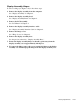
Figure A-9. I/O Panel Removal
To remove and replace the I/O panel, follow these steps:
1. Remove the I/O board.
See the previous subsection in this appendix.
2. Remove the standoff nuts ST1 through ST8
Use a 3/16 nut driver to remove standoff nuts ST1 through ST6 and a 7/32 nut
driver for ST7 and ST8.
3. Remove screw D5.
4. Remove the I/O bracket from the system board.
system board
I/O bracket
8 mm
ST5
ST6
ST7 (4 mm)
4 mm
3 mm
D5 (3 mm)
ST4
ST3
ST2
ST1
ST8 (4 mm)
NOTE: ST1–ST8 are
8-mm standoff nuts