Dell Lifecycle Controller 2 Release 1.
Notes, Cautions, and Warnings NOTE: A NOTE indicates important information that helps you make better use of your computer. CAUTION: A CAUTION indicates either potential damage to hardware or loss of data and tells you how to avoid the problem. WARNING: A WARNING indicates a potential for property damage, personal injury, or death. © 2012 Dell Inc.
Contents Notes, Cautions, and Warnings...................................................................................................2 1 Introduction..................................................................................................................................7 Why Use Lifecycle Controller...................................................................................................................................7 Benefits of Using iDRAC7 with Lifecycle Controller................
Viewing Hardware Inventory—Current or Factory-Shipped..................................................................................22 Exporting Hardware Inventory—Current or Factory-Shipped...............................................................................22 USB Drive.........................................................................................................................................................23 Network Share...........................................................
Rekey Controller With New Local Key.............................................................................................................46 Removing Encryption and Deleting Data..........................................................................................................47 Breaking Mirrored Drives.......................................................................................................................................47 System Setup-Advanced Hardware Configuration.............
9 Lifecycle Log Schema..............................................................................................................65 10 Easy-to-use System Component Names.............................................................................67 11 Using The System Setup And Boot Manager.....................................................................69 Choosing The System Boot Mode.....................................................................................................................
Introduction 1 The Dell Lifecycle Controller provides advanced embedded systems management to perform systems management tasks such as deploy, configure, update, maintain, and diagnose through a graphical user interface. It is delivered as part of iDRAC7 out-of-band solution and embedded Unified Extensible Firmware Interface (UEFI) applications in the latest Dell servers.
• Improved Productivity and Lower Total Cost of Ownership (TCO) — Extending the reach of administrators to larger numbers of distant servers can make IT staff more productive while driving down operational costs such as travel. • Secure Environment — By providing secure access to remote servers, administrators can perform critical management functions, while maintaining server and network security.
• Reduced number of reboots, if multiple components are selected: – During firmware update, the system reboots depending on the components selected. – During firmware rollback, the system reboots only while rolling back iDRAC and Power Supply firmware. NOTE: For more information, see Supported Components table. • Improved user interface navigation. • Improved keyboard navigation, including support for the key to open online help.
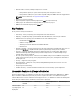
Feature Base Management with IPMI iDRAC7 Express iDRAC7 Express for Blades iDRAC7 Enterprise Device Configuration Yes Yes Yes Yes Diagnostics Yes Yes Yes Yes — — Yes Server Profile — Backup and Export Server Profile Import Yes Yes Yes Yes Part Replacement — Yes Yes Yes Local Updates Yes Yes Yes Yes Driver Packs Yes Yes Yes Yes Hardware Inventory Yes Yes Yes Yes Remote Services (through WSMAN) - Yes Yes Yes Other Documents You May Need In addition to this guide
The Dell OpenManage Server Update Utility User's Guide provides information about using the DVD–based application for identifying and applying updates to the system. • The following system documents are available to provide more information: • The safety instructions that came with your system provide important safety and regulatory information. For additional regulatory information, see the Regulatory Compliance home page at dell.com/ regulatory_compliance.
2 Using Lifecycle Controller This section provides information about launching Lifecycle Controller, enabling or disabling it, and launching it for the first time. Before using Lifecycle Controller, make sure that the network and iDRAC7 are configured. For more information, see iDRAC7 User’s Guide. Launching Lifecycle Controller To launch Lifecycle Controller during the system boot, press the key within 10 seconds after the manufacturer's or service provider’s logo is displayed.
Message Cause Resolution Lifecycle Controller not available Another process is currently using iDRAC. Wait for 30 minutes for the current process to complete, restart the system, and then retry. Lifecycle Controller in Recovery Mode (3-strike policy) Ungracefully exit Lifecycle Controller for 3 consecutive times. Update Lifecycle Controller using Lifecycle Controller repair package through iDRAC.
The System Setup Main Menu page is displayed. 2. In the System Setup Main Menu page, click iDRAC Settings. The iDRAC Settings page is displayed. 3. Click Lifecycle Controller. 4. Under Cancel Lifecycle Controller Actions, select Yes. 5. Go back to the System Setup Main Menu page and click Finish to save the settings. 6. Click Yes to reboot the system.
5. Click Finish to save the settings. NOTE: If Lifecycle Controller Settings are not configured correctly, an error message is displayed. If DHCP is enabled, DHCP IP address is displayed on the Network Settings page. Accessing Help Each Lifecycle Controller screen has a help associated with it. Press the key or click Help (in the upper-right corner) to view the help information about the options on a page. Viewing Readme Click About → View Readme to display the Readme.
Operating System Deployment 3 Using the operating system deployment wizard, you can deploy various custom and standard operating systems on the managed system and configure RAID during installation. Related Links Installing Operating System Installing Operating System Before installing an operating system, make sure that the following prerequisites are met: • Optical DVD drive is connected.
Using Optional RAID Configuration When you install an operating system, you can do one of the following: • Deploy the operating system without configuring RAID • Configure the disks using the optional RAID configuration wizard and deploy the operating system. Alternatively, you can configure RAID through the RAID configuration page from the Hardware Configuration Tab → Configuration Wizards → RAID Configuration .
4. If the standard operating system installation media is validated, continue the installation. Else, insert the correct media and click Next. The Reboot the System page is displayed. Selecting Custom Operating System To install a custom operating system: 1. From the list, select the required custom operating system and click Next. The drivers are extracted into the OEMDRV directory and Lifecycle Controller prompts you to insert the operating system installation media. 2.
Rebooting System Click Finish to reboot the system and continue with the operating system installation. The system boots to the operating system installation media. Post Reboot Scenarios The following table lists the post reboot scenarios, its user actions, and impact.
Monitor 4 Using Lifecycle Controller, you can monitor the hardware inventory and events in the system throughout its lifecycle.
Exporting Hardware Inventory—Current or Factory-Shipped Viewing Hardware Inventory—Current or Factory-Shipped To view the currently-installed or factory-installed hardware components and their configuration details: NOTE: For factory-shipped inventory, the state of few parameters for the installed components displays Unknown. 1. In the left pane, click Hardware Configuration. 2. In the right pane, click Hardware Inventory. 3.
About View and Export Current Inventory About View and Export Factory-Shipped Inventory USB Drive Network Share USB Drive To export to a USB drive: 1. From the Select Device drop-down list, select the USB drive. 2. In the File Location text box, enter a valid directory or sub-directory path on the device. For example, 2011\Nov. If the path is not provided, the file is stored in the root location of the device.
3. In the right pane, click Hardware Inventory. 4. Click View Current Inventory. Lifecycle Controller displays the old hardware inventory. 5. Reboot the server and relaunch Lifecycle Controller. 6. Access Hardware Inventory and click View Current Inventory to view the latest inventory, or click Export Current Inventory to export the latest inventory to an external location.
• System event logs • Firmware inventory • History of firmware updates • Update and configuration events NOTE: The details of the configuration changes are not displayed. • User work notes While viewing the lifecycle log, use different filtering and sorting options. NOTE: As the lifecycle logs are generated by various systems management tools, you may not view the events in lifecycle log immediately after they were logged. To view the Lifecycle Log history and use the filtering options: 1.
To export the Lifecycle Log: 1. In the left pane, click Lifecycle Log. 2. In the right pane, click Export Lifecycle Log. 3. Select either USB Drive or Network Share. 4. If you select the Network Share option, click Test Network Connection to verify if Lifecycle Controller is able to connect to the IP address that you provided. By default, it pings the Gateway IP, DNS server IP, and host IP.
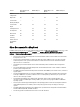
5 Firmware Update Using Lifecycle Controller, the system can be updated using the repositories accessible through FTP or located on a locally-attached USB flash drive, DVD, or network share. Use the Firmware Update wizard to: • View the current versions of the installed applications and firmware. • View the list of available updates. • Select the required updates, downloads (automatic), and apply the updates for the following components listed in the table.
NOTE: If the FTP server or network share is used for updates, configure the network card using Settings wizard before accessing the updates. Table 2.
4. Specify the details. 5. To verify if Lifecycle Controller is able to connect to the IP address that is provided, click Test Network Connection. By default, it pings the Gateway IP, DNS server IP, host IP, and proxy IP (if provided). NOTE: Lifecycle Controller cannot ping to the domain name and does not display its IP address, if the DNS is not able to resolve the domain name. Make sure that the issue with DNS is resolved and retry. 6. Click Next.
Using Local Drive Lifecycle Controller allows you to perform platform updates using locally available DVDs or USB drives, or by using Virtual Media. This flexibility improves the efficiency of the update process when there is high network traffic. After selecting the update repository, Lifecycle Controller automatically detects any necessary updates, and then performs those updates either on components you specifically select, or on all components that Lifecycle Controller has identified by default.
NOTE: If the catalog file is located in the root folder, do not enter the file name in the Catalog Location or Update package path box. However, if the catalog file is located in a sub-directory, enter the sub-directory name (for example, subdirectory). NOTE: If the catalog file or DUP is downloaded from ftp.dell.com, do not copy them into a sub-directory.
Using Proxy FTP Server Using Lifecycle Controller, you can update the firmware by using ftp.dell.com, or by using an internal FTP server or service provider’s FTP server, when you are connected to the Internet through a proxy server. Before updating, make sure the following prerequisites are met: • The network settings are configured (Settings → Network Settings). • The updates are downloaded using the Dell Repository Manager, and the repository is created on an internal FTP server.
For CIFS For NFS example, login-name@myDomain, and if there is no domain, type only the login name. For example, loginname. Password — Password to authenticate the user name. NA Catalog Location or Update package path — Name of the DUP of the location or sub-directory, where the catalog is stored. NOTE: If the catalog file is located in the root folder, do not enter the file name in the Catalog Location or Update package path box.
NOTE: After a rollback, the current and previous version displayed are same. • The Dell Diagnostics, OS driver packs, CPLD, and Lifecycle Controller firmware cannot be rolled back to earlier versions. • The earlier version is available only if the component firmware is updated at least once to a different version. • Every time an image is updated, the earlier version of the firmware image is overwritten.
system restart. For information on how to set TPM settings, see the BIOS User Guide available at dell.com/support/ manuals. When Lifecycle Controller detects that TPM security is set to On with Pre-boot Measurements, a message indicates that certain updates require the recovery password or USB drive with the recovery key. The message also indicates components that affect the BitLocker.
Configure 6 Lifecycle Controller provides various system configuration wizards. Use the configuration wizards to configure system devices. The Configuration Wizards has: • System Configuration Wizards — This includes LCD Panel Security, iDRAC Settings, System Date and Time Configuration, and vFlash SD card Configuration. • Storage Configuration Wizards — This includes RAID Configuration, Key Encryption, and Break Mirror.
Configuring iDRAC To configure iDRAC parameters applicable to the system, such as LAN, common IP settings, IPv4, IPv6, Virtual Media, and LAN user configuration use the iDRAC Settings wizard. NOTE: You can also use the System Setup utility during startup for configuring iDRAC. For more information about the System Setup utility, see the Using The System Setup Program And Boot Manager chapter in this User's Guide. To configure and manage the iDRAC parameters: 1.
Configuring vFlash SD Card Use the licensed feature to enable or disable the vFlash SD card, check the health and properties, and initialize the vFlash SD card. Lifecycle Controller support vFlash SD cards of sizes 1 GB, 2 GB, 8 GB, 16 GB, and 32 GB. NOTE: The options under vFlash SD card are grayed-out if there is no SD card inserted in the slot. See the Integrated Dell Remote Access Controller 7 (iDRAC7) User’s Guide available at dell.
NOTE: If there are any internal storage controller cards on the system, all other external cards cannot be configured. If there are no internal cards, then external cards can be configured. To configure RAID: 1. In the left pane, click Hardware Configuration. 2. In the right pane, click Configuration Wizards. 3. Under Storage Configuration Wizards, click RAID Configuration to launch the wizard. The View Current RAID Configuration and Select Controller page is displayed. 4.
Foreign Configuration Found The Foreign Configuration Found page is displayed only if a foreign configuration disk drive resides on the selected RAID controller. NOTE: If you have selected an S110 RAID controller, the foreign disk drives are displayed as Non-RAID disk drives in Lifecycle Controller. You must initialize them to create a virtual drive.
Minimum Disk Requirement for Different RAID Levels Table 4. : RAID Level and Number of Disks RAID Level Minimum Number of Disks 0 1* 1 2 5 3 6 4 10 4 50 6 60 8 * For S110 RAID controller, a minimum of 2 disks are required. Selecting Physical Disks Use the Select Physical Disks screen to select the physical disks to be used for the virtual drive and select the physical disk drive-related properties.
• • – Read Ahead — The controller reads sequential sectors of the virtual drives when seeking data. The Read Ahead policy may improve system performance if the data is written to sequential sectors of the virtual drives. – No Read Ahead — The controller does not use the Read Ahead policy. The No Read Ahead policy may improve system performance, if the data is random and not written to sequential sectors.
• Non-RAID disk — A single disk drive without any RAID properties. Needs initialization to apply RAID levels. • RAID-ready disk — The disk drive is initialized and a RAID level can be applied. NOTE: Linux and VMware operating systems cannot be installed by using Software RAID controller (S110). To configure software RAID: 1. In the left pane, click Hardware Configuration. 2. In the right pane, click Configuration Wizards. 3.
6. From the Encryption Capability drop-down menu, select Self-encryption. The self-encryption disks (SEDs) are displayed. 7. Select the SEDs and specify the properties, and then click Next. The Virtual Disk Attributes page is displayed. 8. Select the virtual disk parameters, select the Secure Virtual Disk option, and click Next. The Summary page is displayed. 9. To apply the RAID configuration, click Finish.
NOTE: For more information on the specification and configuration-related information for the PERC H710, H710P, and H810 controllers, see the PERC H710, H710P, and H810 Technical Guidebooks. • Encrypt unsecure virtual disks — Enable data encryption on all the security-capable, unsecure virtual drives. NOTE: This option is available if there are virtual drives connected to a security-capable controller. • Rekey controller and encrypted disks with a new key — Replace the existing local key with a new key.
7. In the New Passphrase text box, enter the passphrase that will be associated with the new encryption key identifier Related Links Local Key Encryption Mode Removing Encryption and Deleting Data To remove the encryption and delete the data on the virtual disks: 1. In the left pane, click Hardware Configuration. 2. In the right pane, click Configuration Wizards and click Key Encryption. 3. Select the controller on which you must remove the key that was applied and click Next. 4.
• NICs NOTE: You can configure only one NIC at a time.
• • • • • • • • • • • • • * Emulex LPm16002 Dual Port FC16 HBA Mezzanine H310 Adapter H310 Mini Monolithic H310 Mini Blades H310 Embedded H710 Adapter H710 Mini Blades H710 Mini Monolithic H710P Adapter H710P Mini Blades H710P Mini Monolithic H810 Adapter PCIe Adapter PCIe Backplane Integrated Broadcom NICs are controlled by both BIOS and the settings stored on the device itself.
3. Click Collect System Inventory on Restart. 4. Under Collect System Inventory on Restart, click Enabled,and then click Finish. The system inventory is updated after the next restart. Configuring Local FTP Server If your organization’s users are on a private network that does not have access to external sites, specifically ftp.dell.com, you can provide firmware updates from a locally-configured FTP server.
Accessing Updates on a Local FTP Server As a user, you must know the IP address of the local FTP server to specify the online repository when using the OS Deployment and Firmware Update.
1. Copy the repository created using the Dell Repository Manager to the root directory of the USB drive. 2. Use this USB drive for firmware update. NOTE: For information on creating a repository for your system, see the Dell Repository Manager User Guide at dell.com/support/manuals.
Maintain 7 Using Lifecycle Controller, you can maintain the health a system throughout its lifecycle by using the features such as Part Replacement Configuration and Platform Restore. Platform Restore Lifecycle Controller allows you to create a copy of the server's profile on the vFlash SD card attached to the server. The server profile includes the server component configuration and firmware installed on various components on the server.
• Operating system or any data stored on hard disk drives or virtual drives • vFlash SD card partition information • Lifecycle log • Dell diagnostics • Dell OS Driver Pack • A Local Key Management (LKM) passphrase, if the LKM-based storage encryption is enabled. However, you must provide the LKM passphrase after performing the restore operation. Security The contents of the backup image file cannot be accessed with any application, even if it is generated without a passphrase.
Component Firmware Configuration Security Information* Enclosure NA NA NA * The security information refers to the user credentials that are used to access the components.
System or Feature Behavior During Backup • Lifecycle Controller is disabled. • A partition with a label name SRVCNF is automatically created on the vFlash SD card to store the backup image file. If a partition with the label name SRVCNF already exists, it is overwritten. • Takes up to 45 minutes depending on the server configuration. • Takes a backup of all configuration information. • Does not back up diagnostics and driver pack information. • Backup fails if an AC power cycle is performed.
Import Server Profile Use this feature to apply a backup to the system from which it was taken previously, and restore the system hardware and firmware configuration according to the information stored in the backup image file. For more information about the supported components, see Supported Components. The operation restores the backup information to all the system components that are located in the same physical location (for example, in the same slot) when the backup was performed.
5. If you have secured the backup image file with a passphrase, enter the passphrase (entered during backup) in the Backup File Passphrase box, and click Finish. Related Links System or Feature Behavior During Import Import Server Profile Importing Server Profile After Motherboard Replacement Network Share To import from a network share: 1. In the left pane, select Platform Restore. 2. In the right pane, select Import Server Profile. 3. Select Network Share and click Next. 4.
• Restores everything that was backed up, including Lifecycle controller content. • Import may take up to 45 minutes depending on the server configuration. • Diagnostics or driver pack information is not restored. • If extra restarts occur during tasks executed in Lifecycle Controller, it is because there was an issue while trying to set the device configuration, which attempts to run the task again. Check the Lifecycle Logs for information on the failed device.
Part Replacement Configuration Use this feature to automatically update a new part to the firmware version or the configuration of the replaced part, or both. The update occurs automatically when you reboot your system after replacing the part. It is activated through a license, and can be disabled remotely using Lifecycle Controller-Remote Services, or through the Lifecycle Controller. NOTE: The feature is licensed. Acquire the license to enable the feature.
• Power Supply Units Lifecycle Controller Repair During Power-On Self-Test (POST), if the system displays the message Lifecycle Controller update required, the embedded device that stores Lifecycle Controller may contain corrupt data. To resolve this issue, see the Repairing Lifecycle Controller. Repairing Lifecycle Controller If the message Lifecycle Controller update required appears during power-on self-test (POST), the embedded device that stores Lifecycle Controller may contain corrupted data.
CAUTION: This feature resets the iDRAC to factory defaults, and deletes all iDRAC user credentials, IP address configuration settings, and encryption certificates. It also deletes all the Lifecycle Controller contents such as lifecycle logs that contain the history of all the change events, firmware upgrades and rollback, user comments, and current and factory-shipped hardware and firmware inventory. It is recommended that you export the Lifecycle Log to a safe location before using this feature.
8 Troubleshooting and Frequently Asked Questions This section describes the error messages commonly generated by Lifecycle Controller and provides suggestions for resolving the errors. It also answers questions that are frequently asked by Lifecycle Controller users. Error Messages Each error message that is generated from Lifecycle Controller has a Message ID, Message Description, and Recommended Response Action in a single dialog box.
9. Can I delete Lifecycle Controller? No. 10. Can I use virtual media for the operating system media source during installation? Yes. For more information about iDRAC, see the iDRAC7 User’s Guide available at dell.com/support/manuals. 11. Can I use a virtual USB for my update repository? Yes. For more information, see the iDRAC7 User’s Guide available at dell.com/support/manuals. 12.
Lifecycle Log Schema 9 This section displays a typical lifecycle log schema. PAGE 66
Easy-to-use System Component Names 10 The following table lists the Fully Qualified Device Descriptor (FQDD) of the system components and the equivalent easyto-use names. Table 6. Easy-to-use Names of System Components FQDD of System Component Name Easy-to-use Name RAID.Integrated.1-1 Integrated RAID Controller 1 RAID.Slot.1-1 RAID Controller in Slot 1 NIC.Mezzanine.1B-1 NIC in Mezzanine NIC.Mezzanine.1C-1 NIC.Mezzanine.1C-2 NIC.Mezzanine.3C-2 NonRAID.Integrated.
FQDD of System Component Name Easy-to-use Name Optical.USBFront.1-1 Optical drive connected to front USB 1 Disk.USBInternal.1 Disk connected to Internal USB 1 Optical.iDRACVirtual.1-1 Virtually connected optical drive Floppy.iDRACVirtual.1-1 Virtually connected floppy drive Disk.iDRACVirtual.1-1 Virtually connected disk Floppy.vFlash. vFlash SD Card Partition 2 Disk.vFlash. vFlash SD Card Partition 3 iDRAC.Embedded.1-1 iDRAC System.Embedded.1-1 System HardDisk.List.
Using The System Setup And Boot Manager 11 System Setup enables you to manage your system hardware and specify BIOS-level options. The following keystrokes provide access to system features during startup: Keystroke Description Enters the System Setup. Enters System Services, which opens the Dell Lifecycle Controller 2 (LC2).
mode. Thereafter, you must boot the system in the same boot mode (BIOS or UEFI) to access the installed operating system. Trying to boot the operating system from the other boot mode will cause the system to halt at startup. NOTE: Operating systems must be UEFI-compatible to be installed from the UEFI boot mode. DOS and 32-bit operating systems do not support UEFI and can only be installed from the BIOS boot mode. NOTE: For the latest information on supported operating systems, go to dell.com/ossupport.
System Setup Main Screen NOTE: Press to reset the BIOS or UEFI settings to their default settings. Menu Item Description System BIOS This option is used to view and configure BIOS settings. iDRAC Settings This option is used to view and configure iDRAC settings. Device Settings This option is used to view and configure device settings. System BIOS Screen NOTE: The options for System Setup change based on the system configuration.
System Information Screen Menu Item Description System Model Name Displays the system model name. System BIOS Version Displays the BIOS version installed on the system. System Service Tag Displays the system Service Tag. System Manufacturer Displays the name of system manufacturer. System Manufacturer Displays the contact information of the system manufacturer. Contact Information Memory Settings Screen Menu Item Description System Memory Size Displays the amount of memory installed in the system.
Menu Item Description processors. If this option is set to Disabled, the BIOS only displays one logical processor per core. By default, the Logical Processor option is set to Enabled. QPI Speed Allows you to set the QuickPath Interconnect data rate settings. By default, the QPI Speed option is set to Maximum data rate. NOTE: The QPI speed option displays only when both the processors are installed.
Menu Item Description Level 2 Cache Displays the total L2 cache. Level 3 Cache Displays the total L3 cache. Number of Cores Displays the number of cores per processor. SATA Settings Screen Menu Item Description Embedded SATA Allows the embedded SATA to be set to Off, ATA, AHCI, or RAID mode. By default, Embedded SATA is set to AHCI Mode. Port A Auto enables BIOS support for the device attached to SATA port A. By default, Port A is set to Auto.
Menu Item Description BIOS Boot Settings Allows you to enable or disable BIOS Boot options. NOTE: This option is enabled only if the boot mode is BIOS. UEFI Boot Settings Allows you to enable or disable UEFI Boot options. NOTE: This option is enabled only if the boot mode is UEFI. One-Time Boot Allows you to enable or disable a one-time boot from a selected device.
Menu Item Description CAUTION: Slot disablement must be used only when the installed peripheral card is preventing booting into the Operating System or causing delays in system startup. If the slot is disabled, both the Option ROM and UEFI driver are disabled. Serial Communications Screen Menu Item Description Serial Communication Allows you to select serial communication devices (Serial Device 1 and Serial Device 2) in the BIOS.
Menu Item Description Memory Frequency Allows you to set the memory frequency. By default, the Memory Frequency option is set to Maximum Performance. Turbo Boost Allows you to enable or disable the processor to operate in turbo boost mode. By default, the Turbo Boost option is set to Enabled. C1E Allows you to enable or disable the processor to switch to a minimum performance state when it is idle. By default, the C1E option is set to Enabled.
Menu Item Description TPM Activation Allows you to change the operational state of the TPM. By default, the TPM Activation option is set to No Change. TPM Status Displays the TPM status. TPM Clear CAUTION: Clearing the TPM results in loss of all keys in the TPM. The loss of TPM keys may affect booting to the operating system. Allows you to clear all the contents of the TPM. By default, the TPM Clear option is set to No. Intel TXT Allows you enable or disable Intel Trusted Execution Technology.
Menu Item Description In-System Characterization This field enables or disables In-System Characterization. By default, In-System Characterization is set to Enabled. System And Setup Password Features You can create a system password and a setup password to secure your system. To enable creation of the system and setup password, the password jumper must be set to enabled. For more information on the password jumper settings, see System Board Jumper Settings.
A message prompts you to re-enter the setup password. 8. Re-enter the setup password that you entered earlier and click OK. 9. Press to return to the System BIOS screen. Press again, and a message prompts you to save the changes. NOTE: Password protection does not take effect until the system reboots.
Operating With A Setup Password Enabled If Setup Password is Enabled, enter the correct setup password before modifying most of the System Setup options. If you do not enter the correct password in three attempts, the system displays the message Invalid Password! Number of unsuccessful password attempts: System Halted! Must power down. Even after you shut down and restart the system, the error message is displayed until the correct password is entered.
Key Description Moves to the previous page till you view the main screen. Pressing in the main screen exits the Boot Manager and proceeds with system boot. Displays the System Setup help file. NOTE: For most of the options, any changes that you make are recorded but do not take effect until you restart the system. Boot Manager Screen Menu Item Description Continue Normal Boot The system attempts to boot to devices starting with the first item in the boot order.
iDRAC Settings Utility The iDRAC Settings utility is an interface to setup and configure the iDRAC parameters using UEFI. You can enable or disable various iDRAC parameters using the iDRAC Settings Utility. NOTE: Accessing some of the features on the iDRAC Settings Utility requires the iDRAC7 Enterprise License upgrade. For more information on using iDRAC, see the iDRAC7 User's Guide under Software → Systems Management → Dell Remote Access Controllers, at dell.com/support/manuals.