Dell Lifecycle Controller 2 Version 1.00.
Notes, Cautions, and Warnings NOTE: A NOTE indicates important information that helps you make better use of your computer. CAUTION: A CAUTION indicates potential damage to hardware or loss of data if instructions are not followed. WARNING: A WARNING indicates a potential for property damage, personal injury, or death. Information in this publication is subject to change without notice. © 2012 Dell Inc. All rights reserved.
Contents Notes, Cautions, and Warnings...................................................................................................2 1 Introduction..................................................................................................................................7 Benefits of Using iDRAC7 with Lifecycle Controller.................................................................................................7 Key Features..................................................................
Supported Devices...........................................................................................................................................20 Hardware Diagnostics............................................................................................................................................20 System Setup..........................................................................................................................................................
Virtual Media Configuration.............................................................................................................................40 LAN User Configuration...................................................................................................................................40 Configuring RAID Using Hardware RAID................................................................................................................42 Viewing Current RAID Configuration................
Viewing Lifecycle Log History.................................................................................................................................57 Exporting Lifecycle Log...........................................................................................................................................58 Adding Work Note to Lifecycle Log........................................................................................................................
Introduction 1 The Dell Lifecycle Controller provides advanced embedded systems management to perform systems management tasks such as deploy, configure, update, maintain, and diagnose through a graphical user interface. It is delivered as part of iDRAC7 out-of-band solution and embedded Unified Extensible Firmware Interface (UEFI) applications in the latest Dell servers.
• Custom branding — Rebranding the interface with the customer-centric branding information. • Provide service tag of the system • Provisioning — Entire pre-operating system configuration from a unified interface. • Deploying — Simplified operating system installation with embedded drivers on the Lifecycle Controller. • Download drivers for operating system installation from one of the following sources: – Dell FTP website at ftp.dell.
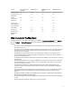
Feature Base Management with IPMI iDRAC7 Express iDRAC7 Express for Blades iDRAC7 Enterprise Firmware Update Yes Yes Yes Yes Operating System Deployment Yes Yes Yes Yes Device Configuration Yes Yes Yes Yes Diagnostics Yes Yes Yes Yes Server Profile Export and Import - - - Yes Part Replacement - - - Yes Local Updates Yes Yes Yes Yes Driver Packs Yes Yes Yes Yes Remote Services (through WSMAN) - Yes Yes Yes Other Documents You May Need In addition to this guid
The following system documents are available to provide more information: • The safety instructions that came with your system provide important safety and regulatory information. For additional regulatory information, see the Regulatory Compliance home page at dell.com/ regulatory_compliance. Warranty information may be included within this document or as a separate document. • The Rack Installation Instructions included with your rack solution describe how to install your system into a rack.
2 Using Lifecycle Controller This section provides information about launching Lifecycle Controller, enabling or disabling it, and launching it for the first time. Before using Lifecycle Controller, make sure that the network and iDRAC7 are configured. For more information, see iDRAC7 User’s Guide. Launching Lifecycle Controller To launch Lifecycle Controller during the system boot, press key within 10 seconds after the manufacturer or service provider’s logo is displayed.
Message Cause Resolution Lifecycle Controller not available Another process is currently using iDRAC. Wait for 30 minutes for the current process to complete, reboot the system, and retry. Lifecycle Controller in Recovery Mode (3-strike policy) Ungracefully exit Lifecycle Controller for 3 consecutive times. Update Lifecycle Controller using Lifecycle Controller repair package through iDRAC or run the repair package DUP through the operating system.
1. Press within five seconds after system start-up. The System Setup Main Menu is displayed. 2. In the System Setup Main Menu page, click iDRAC Settings. The iDRAC Settings page is displayed. 3. Click Lifecycle Controller. 4. Under Cancel Lifecycle Controller Actions, select Yes. 5. Go back to the System Setup Main Menu page and click Finish to save the settings. The system reboots automatically.
Accessing Help Each Lifecycle Controller screen has a help associated with it. Click Help (in the upper-right corner) to display help for the current screen. Viewing Readme Click About → View Readme to display the Readme.
Lifecycle Controller Features 3 This section provides a brief description of the Lifecycle Controller features and helps you familiarize with the wizards to use Lifecycle Controller most effectively. Each feature is a wizard in Lifecycle Controller. Lifecycle Controller supports the following features: • Home — Navigate back to Home screen. • Lifecycle Log — View and export lifecycle log, and add a work note to lifecycle log.
Platform Update Use the Platform Update wizard to: • View the current versions of the installed applications and firmware. • Display the list of available updates.
Related Links Rolling Back to Previous Firmware Versions Hardware Configuration Lifecycle Controller provides different wizards to configure the various system components, and they are: • Configuration Wizards • Hardware Inventory • Delete Configuration and Reset Defaults Configuration Wizards Use the configuration wizards to configure system devices.
NOTE: Incorrect inventory data is displayed or exported after performing Delete Configuration and Reset Defaults. See Viewing and Exporting Current Inventory After Resetting Lifecycle Controller for displaying correct inventory data.
NOTE: Although, Lifecycle Controller has embedded drivers that are factory installed, there are latest drivers available. Before installing the operating system, run the Platform Update wizard to make sure that the latest drivers are available. RAID Configuration During operating system installation, you can do one of the following: • • Deploy the operating system without configuring RAID Configure the disks using the optional RAID configuration wizard and deploy the operating system.
Import Server Profile Use this feature to import and restore the server to a previously known working state from a backup image file that is located on a vFlash SD card, network share, or USB device. You can cancel a restore job using iDRAC Settings utility by pressing F2 during POST and click Yes under Cancel Lifecycle Controller Actions, or reset iDRAC7. This initiates the recovery process and restores the system to a previously known state.
System Setup Advanced Hardware Configuration Lifecycle Controller Advanced Hardware Configuration wizards allow you to configure BIOS, iDRAC, and certain devices such as NIC, and RAID controllers through Human Interface Infrastructure (HII). HII is a UEFI-standard method for viewing and setting a device's configuration. You can utilize a single utility to configure multiple devices that may have different pre-boot configuration utilities.
Lifecycle Controller Repair During Power-On Self-Test (POST), if the system displays the message Lifecycle Controller update required, the embedded device that stores Lifecycle Controller may contain corrupt data. To resolve this issue, see the Repairing Lifecycle Controller. About RAID Configuration Lifecycle Controller supports both software RAID and hardware RAID options. NOTE: You can also configure RAID through the OS Deployment wizard.
Removing Encryption and Deleting Data 23
Lifecycle Controller Operations 4 This section provides the tasks required to perform different operations on the Lifecycle Controller. Viewing Hardware Inventory-Current or Factory Shipped To view the currently installed or factory installed hardware components and their configuration details: NOTE: For factory shipped inventory, the state of few parameters for the installed components displays Unknown. 1. In the left pane, click Hardware Configuration. 2. In the right pane, click Hardware Inventory.
• If you are storing the exported file in a USB flash drive, make sure that a USB flash drive is connected to the managed system. To export the current or factory shipped hardware inventory: NOTE: For factory shipped inventory, the state of few parameters for the installed components displays Unknown. 1. In the left pane, click Hardware Configuration. 2. In the right pane, click Hardware Inventory. 3. Click Export Current Inventory or Export Factory Shipped Hardware Inventory. 4.
• Share Name — Type the path to the shared folder to export the file. For example, type \\192.168.20.26\sharename or \\servername\sharename. • Domain and User Name — Type the domain and user name required to log on to the network share. For example, loginname@myDomain or domain\user name. If there is no domain, type the user name. • Password — Type the correct password. • File Location — Type the sub-directories if any. For example, 2011\Nov.
Updating Platform You can update to the latest version of Lifecycle Controller using the Platform Update wizard. It is recommended that you run the Platform Update wizard on a regular basis to access the latest updates. You can update the component firmware either using update repositories or individual DUPs (single component DUP.) NOTE: Make sure that the file name for the single component DUPs does not have any blank space. To update the platform: 1. In the left pane, click Platform Update. 2.
Comparing Firmware Versions Using Single Component DUPs Using Repository Using Local Drive Using Local or FTP Server Using Network Share Updating or Rolling Back Devices That Affect Trusted Platform Module Settings Using Single Component DUPs To use single component DUPs: NOTE: Make sure that the file name for the single component DUPs does not have any blank space. In the Catalog Location or Update package path box, enter the name of the DUP (for example, APP_WIN_RYYYZZZ.
• User Name — The user name required for authentication on the proxy server. • Password — The password required for authentication on the proxy server. • Type — The type of proxy server. HTTP and SOCKS 4 proxy types are supported by Lifecycle Controller. Related Links Using Repository Using Single Component DUPs Using Network Share To use a shared folder over a network, select Network Share (CIFS or NFS) and enter the details provided in the following table: Table 1.
1. In the left pane, click Platform Update. 2. In the right pane, click Launch Platform Rollback. The Platform Rollback page displays a list of components for which rollback is available and the later versions are selected by default. 3. Select the required rollback image(s) and click Apply. After the update process is complete, the system reboots. When applying more than one update, the system may reboot between updates directly into Lifecycle Controller and continue updating.
Installing Operating System Before installing the operating system, make sure that the following prerequisites are met: • Optical DVD drive is connected. • Hard disk is connected. • Virtual media is connected. For more information, see iDRAC User’s Guide. • Software RAID or PERC controller is installed with the latest firmware, and at least one physical disk is available for creating the virtual disk.
The RAID configuration is applied on the disks, and OS Deployment wizard navigates to the Select an Operating System page. Selecting Operating System You can select an operating system based on its availability and user preference.
1. Select the option Any Other Operating System, and click Next. No drivers are extracted. Therefore, prepare the drivers for the required operating system. 2. Insert the operating system installation media with all the operating system components that are specific to your requirements and click Next. NOTE: Lifecycle Controller does not validate the media.
5. – View Only – Disable Click Finish to apply the changes. System Control Panel Access Options Lifecycle Controller front panel security configuration enables an administrator to restrict access to control panel interface. The options available are: • View and Modify — You can obtain information and make changes using the system control panel interface. • View Only — You can move through the data screens to obtain information using the system control panel interface.
5. Click Finish to apply the new iDRAC settings. LAN Configuration To view and configure LAN: 1. From iDRAC Configuration, select LAN Configuration. 2. Enter details for iDRAC LAN, IPMI Over LAN, MAC Address, and NIC Selection. Table 2. : LAN Configuration Attributes Attributes Description Values iDRAC LAN Enabling iDRAC LAN activates the remaining controls. Disabling Enable or Disable iDRAC LAN deactivates the controls.
Attribute Description Values communicating with the nearest router or hub. When auto-negotiate is off, you must set the Duplex Mode and Network Speed values manually. LAN Speed Configures the network speed to match the user's network environment. This option is not available if Auto-Negotiate is set to On. 10 Mb, 100 Mb, and 1000 Mb LAN Duplex Configures the duplex mode to match the user's network environment. This option is not available if Auto- Negotiate is set to On.
1. From IP Configuration, go to IPv4 Configuration and enable or disable the protocol. 2. Set the RMCP+ encyption key. 3. Specify the IP Address Source. 4. Specify user-configured settings. 5. Click Next to proceed. Attribute Description Values IPv4 iDRAC NIC IPv4 protocol support. Disabling IPv4 deactivates the controls. Enable or Disable RMCP+ Encryption Key RMCP+ encryption key configuring (no blanks allowed). The default setting is all zeros (0).
3. Specify user-configured settings for alternate Ethernet IP Address. 4. Click Next to save your settings and proceed. Attribute Description Values IPv6 iDRAC NIC IPv6 protocol support. Disabling IPv6 deactivates the remaining controls Enable or Disable IP Address Source The ability of the iDRAC NIC to acquire an IPv6 address from the DHCP server. Disabling IP Address Source deactivates the Ethernet IP Address, Prefix Length, and Default Gateway controls.
Settings Values and Description DNS Server 2 (Secondary DNS Server) Maximum value of FFFF:FFFF:FFFF:FFFF:FFFF:FFFF:FFFF:FFFF Virtual Media Configuration The Virtual Media is available only if the system includes iDRAC7 Enterprise. Use the Virtual Media Configuration wizard to set control modes for the available Virtual Media devices. See the Integrated Dell Remote Access Controller 7 (iDRAC7) User’s Guide available at support.dell.com/manuals for more information on supported Virtual Media devices.
Table 8. : LAN User Configuration Parameter Description Value Provisioning Server Address Enter provision server address. Criteria IPV4 or IPV6 or Host Name Auto-Discovery Discovers the provisioning server. Enable or Disable Account Access Disabling account access deactivates all other fields on the LAN User Configuration. Enable or Disable NOTE: The option is available only for the ’root’ user. Account Username Enables the modification of an iDRAC username.
Smart Card Authentication You can set the following values for smart card authentication: • Enabled — Enabling Smart Card login disables all command-line out‑of-band interfaces including SSM, Telnet, Serial, remote RACADM, and IPMI over LAN. • Disabled — On subsequent logins from the graphical user interface (GUI), the regular login page displays. All command-line out-of-band interfaces—including Secure Shell (SSH), Telnet, Serial, and RACADM—are set to their default states.
Viewing Current RAID Configuration The View Current RAID Configuration and Select Controller page displays the attributes of any virtual disks already configured on the supported RAID controllers attached to the system. You have two options: • Accept the existing virtual disks without making changes. To select this option, click Back. If you have to install the operating system on an existing virtual disk, make sure that the virtual disk size and RAID level are correct.
• RAID 6 — Stripes data across the physical disks, and uses two sets of parity information for additional data redundancy. If one or two physical disks fail, the data can be rebuilt using the parity information. RAID 6 offers good data redundancy and read performance but slower write performance. • RAID 10 — Combines mirrored physical disks with data striping. If a physical disk fails, data can be rebuilt using the mirrored data. RAID 10 offers good read and write performance with good data redundancy.
Setting Virtual Disk Attributes Use this page to specify the values for the following virtual disk attributes: • In the Size box, specify the size of the virtual disk. • From the Stripe Element Size drop-down menu, select the stripe element size. The stripe element size is the amount of disk space a stripe consumes on each physical disk in the stripe. The Stripe Element Size drop-down menu may contain more options than initially displayed on the screen.
Configuring RAID Using Software RAID For the S110 controller, make sure to change the SATA Controller option to RAID Mode. To do this through BIOS, the latest BIOS version must be installed. For more information on the BIOS versions for different systems, see Lifecycle Controller Readme. NOTE: If you have an older BIOS, you can configure RAID only through Option ROM. Use this feature to configure RAID if a PERC S110 controller on the motherboard is present in the system.
3. Under Storage Configuration Wizards, click RAID Configuration to launch the wizard. The View Current RAID Configuration and Select Controller page is displayed and along with information on whether the displayed virtual disk is secure. 4. Select the controller and click Next. If the non RAID disks are attached to the selected controller, select the non-RAID physical disks and click Next to initialize them. Else, the Select RAID Level page is displayed.
Enabling or Disabling vFlash Make sure to set the write-protect latch on the vFlash SD card to Off position. If set to Enabled, the vFlash SD card is configured as a virtual drive that appears in the BIOS boot order, allowing you to boot from the vFlash SD card. If set to Disabled, virtual flash is not accessible. To enable or disable vFlash SD card: 1. In the left pane, click Hardware Configuration. 2. In the right pane, click Configuration Wizards. 3.
NOTE: All virtual disks created under the same physical disk are automatically encrypted. 1. In the left pane, click Hardware Configuration. 2. In the right pane, click Configuration Wizards. 3. Under Storage Configuration wizards, click Key Encryption. 4. Select the controller that is encrypted and click Next. NOTE: The encryption mode (Local Key Encryption) applied to the selected controller does not change. 5. Select Encrypt unsecure virtual disks and click Next. 6.
3. Under Storage Configuration wizards, click Key Encryption. 4. Select the controller to which the local key is applied and click Next. 5. In the Existing Passphrase text box, enter the existing passphrase associated with the displayed Encryption Key Identifier. 6. In the New Encryption Key Identifier text box, enter the new identifier. The Encryption Key Identifier is a passphrase hint; you must enter the passphrase when Lifecycle Controller prompts with this hint. 7.
FTP Authentication Although you must provide the user name and password for the FTP server, Lifecycle Controller supports anonymous login to the FTP server using the FTP server address to download the catalog information. If you use a firewall, you should configure it to allow outgoing FTP traffic on port 21. The firewall must be configured to accept incoming FTP response traffic. Requirements for a Local FTP Server The following requirements apply when configuring a local FTP server.
– Address — The IP address of the local FTP server or ftp.dell.com. – User Name — The user name to access the FTP location. – Password — The password to access this FTP location. – Proxy Server — The server host name or the IP address of the proxy server. – Proxy Port — The port number of the proxy server. – Proxy Type — The type of proxy server. HTTP and SOCKS 4 proxy types are supported by Lifecycle Controller. – Proxy User Name — The user name required for authentication on the proxy server.
• Enable Collect System Inventory On Restart. If it is disabled, the cache of system inventory information may become stale if new components are added without manually entering Lifecycle Controller after turning the system on. In the manual mode, you must press after part replacement during reboot. • The replaced card or part must belong to the same family as the previous component. To perform part firmware and configuration update: 1. In the left pane, click Platform Restore. 2.
Alternatively, to generate the encrypted backup file without using a passphrase, click Finish. 4. In the Backup File Passphrase field, enter a passphrase. For example, Rt@#12tv. NOTE: A valid passphrase contains 8 to 32 characters. It must include a combination of uppercase and lowercase letters, numbers, symbols, and without spaces. The passphrase is optional and if used for backup, it must be used during restore. 5. In the Confirm Passphrase field, re-enter the passphrase and click Finish.
System or Feature Behavior during Export • Takes up to 15 minutes depending on the server configuration. • Lifecycle Controller exports the backup image file in the Backup __.img format. The is copied from the backup image file name. The is the time when the backup was initiated. • After a successful export, the event is logged in the Lifecycle Log.
Network Share To import from a network share: 1. In the left pane, select Platform Restore. 2. In the right pane, select Import Server Profile. 3. Select Network Share and click Next. 4. Select CIFS or NFS, enter the backup file name along the with directory, sub-directory path, and click Next. 5. Select either Preserve configuration or Delete Configuration. 6. – Preserve configuration — Preserves the RAID level, virtual disk, and controller attributes.
• If extra reboots occur during tasks executed in Lifecycle Controller, it is because there was an issue while trying to set the device configuration, which attempts to run the task again. Check the Lifecycle Logs for information on the failed device. • Import operation for a card fails if the slot in which it was installed earlier has changed. • The import operation restore only Perpetual license. The evaluation and permanent licenses are not restored.
NOTE: The details of the configuration changes are not displayed. • User work notes While viewing the lifecycle log, use different filtering and sorting options. NOTE: As the lifecycle logs are generated by various systems management tools, you may not view the events in lifecycle log immediately after they were logged. To view the Lifecycle Log history and use the filtering options: 1. In the left pane, click Lifecycle Log. 2. In the right pane, click View Lifecycle Log History.
3. Select either USB Device or Network Share. 4. If you select Network Share option, click Test Network Connection to verify if Lifecycle Controller is able to connect to the IP address that you provided. By default, it pings the Gateway IP, DNS server IP, and host IP. NOTE: Lifecycle Controller cannot ping to the domain name and does not display its IP address if the DNS is not able to resolve the domain name. Make sure that the issue with DNS is resolved and retry. 5. Click Finish.
5 Troubleshooting and Frequently Asked Questions This section describes the error messages commonly generated by Lifecycle Controller and provides suggestions for resolving the errors. It also answers questions that are frequently asked by Lifecycle Controller users. Error Messages The following table lists some of the errors: Error Message Resolution Failed to Copy Driver Files The drivers required to install the operating system are corrupted.
Error Message Resolution Drivers pack not found OR Error populating OS list Lifecycle Controller cannot find the drivers required to install the operating system. To resolve this issue, perform a platform update. See Updating Platform for more information. The repository you selected as an update source failed an integrity check. Recreate the repository, download it again, or provide an alternate source to be used. This error may be caused by temporary network problems.
Error Message Resolution RAID configuration failed Lifecycle Controller failed when creating the RAID configuration. To resolve this issue: 1. Reboot the system. 2. Re-enter Lifecycle Controller by pressing the key. 3. Try again to create the RAID configuration. Generic Failure Lifecycle Controller experienced an unidentified error when creating the RAID configuration. To resolve this issue: 1. Reboot the system. 2. Re-enter Lifecycle Controller by pressing the key. 3.
Error Message Resolution Invalid USB and Network Share Folder Location Provide the valid folder location. The Update Package is not supported for this System Ensure that the update package is supported on the system. Invalid Update Package Ensure that the update package is not corrupt or tampered. The Server Profile backup operation that was initiated from Lifecycle Controller completed with errors. The RAC log contains the names of the components that failed during backup.
1. Go to ftp.dell.com → LifecycleController and download the file named LC2_Repair_Package_1.a.b.c.d.usc (or newer version) to a temporary location. 2. Connect to iDRAC on your system using the iDRAC Web interface. For more information on iDRAC, see the Integrated Dell Remote Access Controller 7(iDRAC7) User’s Guide. 3. In the iDRAC7 Web interface, go to Overview → iDRAC Settings → iDRAC Firmware Update. The Firmware Update page is displayed. 4.
9. Can I delete Lifecycle Controller? No. 10. Can I use virtual media for the operating system media source during installation? Yes. See the iDRAC7 User’s Guide for your system’s iDRAC device for more information (available at support.dell.com/manuals). 11. Can I use a virtual USB for my update repository? Yes. See the iDRAC7 User’s Guide for more information (available at support.dell.com/manuals). 12.
Lifecycle Log Schema 6 This section displays a typical lifecycle log schema. PAGE 68
Easy-to-use System Component Names 7 The following table lists the Fully Qualified Device Descriptor (FQDD) of the system components and the equivalent easyto-use names. Table 11. Easy-to-use Names of System Components FQDD of System Component Name Easy-to-use Name RAID.Integrated.1-1 Integrated RAID Controller 1 RAID.Slot.1-1 RAID Controller in Slot 1 NIC.Mezzanine.1B-1 NIC in Mezzanine NIC.Mezzanine.1C-1 NIC.Mezzanine.1C-2 NIC.Mezzanine.3C-2 NonRAID.Integrated.
FQDD of System Component Name Easy-to-use Name Optical.USBFront.1-1 Optical drive connected to front USB 1 Disk.USBInternal.1 Disk connected to Internal USB 1 Optical.iDRACVirtual.1-1 Virtually connected optical drive Floppy.iDRACVirtual.1-1 Virtually connected floppy drive Disk.iDRACVirtual.1-1 Virtually connected disk Floppy.vFlash. vFlash SD Card Partition 2 Disk.vFlash. vFlash SD Card Partition 3 iDRAC.Embedded.1-1 iDRAC System.Embedded.1-1 System HardDisk.List.