Configuring VLAN Settings in Lifecycle Controller for Dell PowerEdge Servers This Dell Technical White Paper provides detailed information about configuring VLAN settings on a network port using Lifecycle Controller on the Dell 12th generation servers and later versions.
Date Description October 2013 Initial release THIS WHITE PAPER IS FOR INFORMATIONAL PURPOSES ONLY, AND MAY CONTAIN TYPOGRAPHICAL ERRORS AND TECHNICAL INACCURACIES. THE CONTENT IS PROVIDED AS-IS, WITHOUT EXPRESS OR IMPLIED WARRANTIES OF ANY KIND. © 2013 Dell Inc. All rights reserved. Reproduction of this material in any manner whatsoever without the express written permission of Dell Inc. is strictly forbidden. For more information, contact Dell.
Contents Revisions .................................................................................................................................................................................................. 1 Introduction ........................................................................................................................................................................................... 4 1 Network Setup for LC GUI with VLAN Settings ...........................................
Introduction This document provides information about setting up and configuring VLAN settings on a Network Port using Lifecycle Controller on the 12th generation servers of Dell to the users. The VLAN Tagging implementation is based on IEEE 802.1Q. Lifecycle Controller supports the static VLANs which are port-based. It supports the VLAN IDs 1–4094 and the Priority 0–7. The scope of VLAN Settings explained in this white paper is limited to the Lifecycle Controller.
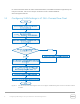
1 Network Setup for LC GUI with VLAN Settings Figure 1 VLAN setup to use network features from LC GUI As shown in the flow diagram here, you can select a Server Management domain for the Server Management activities on the Dell PowerEdge servers. This can be achieved by using a VLAN, where the management ports can be configured to operate with a particular VLAN ID. This provides an additional security to the system management activities.
For more information about the earlier mentioned features, and additional features supported by the Lifecycle Controller, refer to the Lifecycle Controller1.3 User’s Guide available at dell.com/support/manuals. 1.
1.2 Configuring VLAN Settings in LC GUI 1. To start Lifecycle Controller, press during POST.
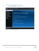
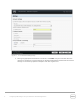
2. In the left pane, click Settings, and then click Network Settings. Figure 4 1.2.1 LC GUI Settings Page Setting DHCP Server as the IP Address Source 1. From the NIC Card drop-down menu, select a NIC card. 2. From the IP Address drop-down menu, select DHCP. 3. To type a priority level and VLAN ID within the specified value, under Lifecycle Controller VLAN Settings, select Enable. Note: Make sure network cable is connected to a NIC card which is selected for VLAN settings.
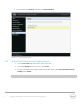
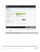
Figure 5 LC UI Network Settings Page 4. After typing appropriate information in the boxes, click Finish. Lifecycle Controller takes few minutes to configure the network settings. A message is displayed to indicate that the network settings are successfully updated. A sample screen shot is given here.
Figure 6 LC UI Network Settings success message 5. To check the IP address properties, in the left pane click Settings, and then click Network Settings. Note: 12G servers support only the IPv4 addresses.
Figure 7 11 LC GUI Network Settings Page Configuring VLAN Settings in Lifecycle Controller for Dell PowerEdge Servers
1.2.2 Setting Static IP as the IP Address Source 1. From the NIC Card drop-down menu, select a NIC Card. 2. From the IP Address drop-down menu, select Static, and then type data in the IP Address Properties boxes. 3. To type the priority level and VLAN ID within the specified value, under Lifecycle Controller VLAN Settings, select Enable. Figure 8 VLAN Settings Enabled Note: Make sure that the network cable is connected to the NIC card that is selected for the VLAN settings.
Figure 9 13 LC UI Network Settings success message Configuring VLAN Settings in Lifecycle Controller for Dell PowerEdge Servers
2 Error Scenarios and Resolution 1) LNK0005: Unable to Connect to DHCP server Description: If you make sure that the network cable is connected and the network configuration settings are correct, then an error message will be displayed. A sample screen shot is given here. Solution: a. Try to verify if the network cable is connected and the network configuration settings are correct. Else, retry the operation. b.
3 Warning Scenarios and Resolution 1) Invalid VLAN ID Description: A warning message is displayed to indicate if any letters, special character,s or a value typed is not within 1–4094. Solution: a) Type a numeric value between 1-4094 for VLAN ID. Figure 10 LC UI Network Settings invalid VLAN ID warning message 2) Invalid Priority Number Description: A warning message is displayed to indicate if any letters, special characters, or a value typed is not between 0-7.
Figure 11 LC UI Network Settings invalid Priority Number warning message 16 Configuring VLAN Settings in Lifecycle Controller for Dell PowerEdge Servers
4 Frequently Asked Questions 1. Can I use the FC Network Cards for Lifecycle Controller VLAN Settings? Ans: You cannot use the FC Network Cards. 2. What are the VLAN Settings required to access the ftp.dell.com? Ans: The default VLAN Settings (VLAN ID–1 and Priority–0). 3. Can I configure multiple ports and use in LC UI? Ans: The LC GUI works with the latest configured port.
5 Best Practices For recommended actions in case of any errors while configuring DHCP or STATIC Server, refer to the “Error Scenarios and resolution”, “Warning Scenarios and resolution” sections in this white paper. 5.1 Technical White Paper Table 1 Technical white paper definition 18 Is Is not Is tested and validated on all the 12G servers, having LC2 1.3.0 and iDARC 1.50.50 versions. Is NOT supported on 11G or 12G servers having LC2 1.2.0 version or earlier.
A Supported Network Interface Cards For VLAN Settings Using LC GUI To configure VLAN Settings, on the Lifecycle Controller page, go to Settings Network Settings for all the Dell supported network cards such as Broadcom, Intel, Qlogic, and Mellanox. Note: All FC cards are not supported for VLAN Settings in LC UI such as Brocade, Emulex, and Qlogic. To know the cards are either Ethernet or FC, refer to the Lifecycle Controller1.3 User’s Guide available at dell.com/support/manuals. Sl.
15 Broadcom 57840S Quad Port 10G SFP+ Rack NDC Broadcom 16 Broadcom 57840S-k Quad Port 10GbE Blade KR NDC Broadcom 17 i540 DP 10G BASE-T ADAPTER (Full Height) Intel 18 i540 DP 10G BASE-T ADAPTER (Low Profile) Intel 19 Intel DP 10GBASE SFP+ (Full Height) Intel 20 Intel DP 10GBASE SFP+ (Low Profile) Intel 21 i350 DP 1G ADAPTER (Full Height) Intel 22 i350 DP 1G ADAPTER (Low Profile) Intel 23 i350 QP 1G ADAPTER (Full Height) Intel 24 i350 QP 1G ADAPTER (Low Profile) Intel 25 i
37 Mellanox ConnectX-3 Dual Port 10 GbE DA/SFP+ Network Adapter (Full Height) Mellanox 38 Mellanox ConnectX-3 Dual Port 10 GbE DA/SFP+ Network Adapter (Low Profile) Mellanox 39 Mellanox ConnectX-3 Dual Port 40 GbE QSFP+ Network Adapter (Full Height) Mellanox 40 Mellanox ConnectX-3 Dual Port 40 GbE QSFP+ Network Adapter (Low Profile) Mellanox Configuring VLAN Settings in Lifecycle Controller for Dell PowerEdge Servers
B Unsupported Network Interface Cards For VLAN Settings Using LC GUI To configure VLAN settings from LC GUI (as these cards are not listed on the Network Settings page) and to know the cards are either Ethernet or FC, refer to the Lifecycle Controller1.3 User’s Guide available at dell.com/support/manuals. 22 Sl.
17 CRD,CTL,FC8,HB,QME2572,BLDE,V2 Qlogic 18 QLE2460 8Gbps Single Port (Full Height) Qlogic 19 QLE2462 8Gbps Dual Port (Full Height) Qlogic 20 QLE2560 8Gbps Single Port Qlogic 21 QLE2562 8Gbps Dual Port Qlogic 22 CRD,CTL,FC16,2P,LPE16002,EMLX (Full Height) Emulex 23 CRD,CTL,FC16,2P,LPE16002,LP,EMLX (Low Profile Emulex 24 CRD,CTL,FC16,1P,LPE16000,EMLX (Full Height) Emulex 25 CRD,CTL,FC16,1P,LPE16000,LP,EMLX (Low Profile) Emulex 26 CRD,CTL,FC8,HBA,SC,LPE12000,V2 (Full Height) E
C Configuration Details Table 2 24 Component table Component Description Firmware version LC2 1.3.0 and iDRAC 1.50.
D Additional Resources Support.dell.com is focused on meeting your needs with proven services and support. DellTechCenter.com is an IT Community where you can connect with Dell Customers and Dell employees for the purpose of sharing knowledge, best practices, and information about Dell products and installations. Referenced or recommended Dell publications: Dell EqualLogic Configuration Guide: http://en.community.dell.com/dell-groups/dtcmedia/m/mediagallery/19852516/download.