Dell Lifecycle Controller 2 Release 1.
Notes, Cautions, and Warnings NOTE: A NOTE indicates important information that helps you make better use of your computer. CAUTION: A CAUTION indicates either potential damage to hardware or loss of data and tells you how to avoid the problem. WARNING: A WARNING indicates a potential for property damage, personal injury, or death. © 2013 Dell Inc. All Rights Reserved.
Contents 1 Introduction..................................................................................................................................7 Why Use Lifecycle Controller................................................................................................................................... 7 Benefits of Using iDRAC7 with Lifecycle Controller................................................................................................. 7 What's New in this Release?..................
Hardware Inventory View and Export.....................................................................................................................25 About View and Export Current Inventory.............................................................................................................. 25 About View and Export Factory-Shipped Inventory............................................................................................... 25 Viewing Hardware Inventory—Current or Factory-Shipped......
Applying the Local Key On RAID Controller..................................................................................................... 49 Local Key Encryption Mode....................................................................................................................................50 Encrypting Unsecure Virtual Disks...................................................................................................................50 Rekey Controller With New Local Key....................
Performing Hardware Diagnostics...................................................................................................................67 8 Troubleshooting and Frequently Asked Questions..............................................................69 Error Messages...................................................................................................................................................... 69 Frequently Asked Questions.......................................................
Introduction 1 The Dell Lifecycle Controller provides advanced embedded systems management to perform systems management tasks such as deploy, configure, update, maintain, and diagnose through a graphical user interface. It is delivered as part of iDRAC7 out-of-band solution and embedded Unified Extensible Firmware Interface (UEFI) applications in the latest Dell servers.
• Improved Productivity and Lower Total Cost of Ownership (TCO) — Extending the reach of administrators to larger numbers of distant servers can make IT staff more productive while driving down operational costs such as travel. • Secure Environment — By providing secure access to remote servers, administrators can perform critical management functions, while maintaining server and network security.
• Synchronized mouse cursor while using Lifecycle Controller through iDRAC Virtual Console. Must have BIOS version 1.3.x or later. • Removed task validation post reboot after a firmware update operation. This has reduced the time taken to complete the firmware update. NOTE: While performing firmware update, if CSIOR is disabled, after completing the update on all the components, Lifecycle Controller performs a single validation task.
• Supports H730P controller on the Equinox server. Licensable Features in Lifecycle Controller Lifecycle Controller features are available based on the type of license (Basic Management, iDRAC7 Express, iDRAC7 Express for Blades, or iDRAC7 Enterprise) that you purchase. Only licensed features are available in the Lifecycle Controller Web interface. For more information about managing licenses, see the iDRAC7 User’s Guide.
Device ID Indicates the service tag of the server on which an iDRAC is installed. License – – – – – Entitlement ID: Indicates a unique ID provided by the manufacturer. Status: Indicates the status of the installed license. The different licenses statuses are: a. b. c. Description: Indicates the license type along with a unique ID. License Type: Indicates the type of license of the device. For example, Evaluation, Express, or Enterprise.
• Lifecycle Controller Web Services Interface Guide–Windows and Linux Social Media Reference To know more about the product, best practices, and information about Dell solutions and services, you can access the social media platforms such as Dell TechCenter and YouTube. You can access blogs, forums, white papers, how-to videos, and so on from the Lifecycle Controller wiki page at www.delltechcenter.com/lc. For Lifecycle Controller documents and other related firmware documents, see www.dell.
Using Lifecycle Controller 2 This section provides information about launching Lifecycle Controller, enabling or disabling it, and launching it for the first time. Before using Lifecycle Controller, make sure that the network and iDRAC7 are configured. For more information, see iDRAC7 User’s Guide. Launching Lifecycle Controller To start Lifecycle Controller during the system start, press thekey within 10 seconds after the manufacturer's or service provider’s logo is displayed.
Restoring System Config by Manually Entering ServiceTag When you do not have a backup on a vFlash SD card: 1. Lifecycle Controller automatically displays the following message on the home page. Click Yes. Unable to Detect Service Tag. Do you want to enter the service tag label? NOTE: Before you restore the system configuration, make sure that the latest version of BIOS is installed. 2. On the Service Tag Settings page, type the service tag, and then click Apply.
Enabling Lifecycle Controller To boot into Lifecycle Controller during startup: 1. Press the key within five seconds after system start-up. The System Setup Main Menu page is displayed. 2. Click iDRAC Settings. The iDRAC Settings page is displayed. 3. Click Lifecycle Controller. 4. Select Enabled. 5. On the System Setup Main Menu page, click Finish to save the settings. 6. Click Yes to restart the system.
Using Lifecycle Controller for the First Time After you start Lifecycle Controller for the first time, by default the Settings → Language and Keyboard page is launched. However, the Home page is displayed after subsequent launches. 1. By default, the Language and Keyboard Layout are English and United States. To change language and keyboard layout, select the Language and Keyboard Layout, and then click Next. The Network Settings page is displayed. 2.
You can either enable or disable this settings. For more information about the fields in this section, click the Help link in the upper-right corner of the Network Settings page. 5. Click Finish to save the settings. NOTE: If Lifecycle Controller Settings are not correctly configured, an error message is displayed. NOTE: If you are unable to connect to a network, verify the settings. For more information about correct network settings, contact your network administrator.
Installing Operating System in Unattended Mode Viewing iDRAC License Information Restoring a Server Profile from vFlash Backup 18
Operating System Deployment 3 Using the operating system deployment wizard, you can deploy various custom and standard operating systems on the managed system and configure a RAID during installation. Related Links Installing Operating System Installing Operating System in Unattended Mode Installing Operating System Before installing an operating system (OS), make sure that the following prerequisites are met: • Optical DVD drive, or a virtual media (ISO image) is connected virtually to a server.
NOTE: If you select an operating system that supports UEFI boot mode, BIOS and UEFI options are provided for selecting the boot mode. 6. Restart the system. The operating system is automatically installed on the selected virtual disk. Related Links Selecting Operating System Rebooting System Using Optional RAID Configuration Using Optional RAID Configuration When you install an operating system, you can do one of the following: • Deploy the operating system without configuring RAID.
The drivers are extracted to the OEMDRV directory, and Lifecycle Controller prompts you to insert the operating system installation media. 2. Lifecycle Controller displays two installation modes — UEFI or BIOS. Select one of the options and click Next. If the selected operating system does not support the UEFI mode, the UEFI option is grayed-out.
either cancel operating system installation or reenter Lifecycle Controller after restarting the system, or when an AC power-cycle operation is performed. NOTE: Although, Lifecycle Controller has embedded drivers that are factory-installed, there are latest drivers available. Before installing the operating system, update the latest Lifecycle Controller driver packs to make sure that the latest drivers are available on the server.
Scenario User Action and Impact During POST, the system prompts you to press a key to boot into the operating system installation media Press any key to begin the operating system installation; else, the system boots to the hard disk drive and not the operating system installation media. Operating system installation is interrupted and the system restars before the installation is completed. The system prompts you to press a key to boot from the operating system installation media.
Monitor 4 Using Lifecycle Controller, you can monitor the hardware inventory and events in the system throughout its lifecycle.
Exporting Hardware Inventory—Current or Factory-Shipped Viewing Hardware Inventory—Current or Factory-Shipped To view the currently-installed or factory-installed hardware components and their configuration details: NOTE: For factory-shipped inventory, the state of few parameters for the installed components is displayed as Unknown. 1. In the left pane, click Hardware Configuration. 2. In the right pane, click Hardware Inventory. 3.
The HardwareInventory __.xml or FactoryShippedHWInventory_.xml file is copied to the specified location. For the current inventory, the time stamp is in the format yyyy-mm-ddthh:mm:ss, where ‘t’ indicates time. Related Links About View and Export Current Inventory About View and Export Factory-Shipped Inventory USB Drive Network Share USB Drive To export hardware-related inventory to a USB drive: 1. From the Select Device drop-down menu, select a USB drive. 2.
Viewing or Exporting Hardware Inventory After Part Replacement To view or export the hardware inventory after part replacement: 1. Launch Lifecycle Controller. 2. In the left pane, click Hardware Configuration. 3. In the right pane, click Hardware Inventory. 4. Click View Current Inventory. Lifecycle Controller displays the old hardware inventory. 5. Restart the server and relaunch Lifecycle Controller. 6.
Related Links Viewing Lifecycle Log History Exporting Lifecycle Log Adding Work Note to Lifecycle Log Viewing Lifecycle Log History Use this feature to view: • System event logs • History of firmware updates • Update and configuration events NOTE: The details of the configuration changes are not displayed. • User work notes While viewing the lifecycle log, use different filtering and sorting options.
Exporting Lifecycle Log Use this feature to export the Lifecycle Log information to a compressed file (.gz format) that has log files in an .xml file. Store the XML file in a USB drive or network share. For more information about the schema, see Lifecycle Log Schema. Before exporting the lifecycle log, make sure the following prerequisites are met: • To export the file to a USB drive, make sure that a USB drive is connected to the managed server.
5 Firmware Update Using Lifecycle Controller, the system can be updated using the repositories accessible through FTP or located on a locally-attached USB drive, DVD, or network share. Use the Firmware Update page to: • View the current version of the installed applications and firmware. • View a list of available updates. • Select the required updates, downloads (automatic), and then apply the updates for the following components listed in the table.
Version Compatibility Updating Firmware Download Methods The following table lists the various locations or media and methods to perform the updates: NOTE: If the FTP server or network share is used for updates, configure the network card using Settings wizard before accessing the updates. Table 2.
NOTE: During BIOS update, due to security reasons, the progress bar stops at 40 seconds, jumps to 1 minute 50 seconds after a while, and then completes. To update the firmware: 1. In the left pane, click Firmware Update. 2. In the right pane, click Launch Firmware Update. 3. To indicate the repository where the firmware file is stored, select any one of these update repositories: FTP Server, Local Drive, or Network Share, click Next. The Enter Access Details page is displayed. 4.
NOTE: Make sure that the repository (catalog file) and DUPs that are downloaded from ftp.dell.com are copied into the root folder of the source. • Local Drive — Use a USB drive, Dell Server Updates DVD, or Lifecycle Controller OS Driver Packs DVD.
• Connect USB drive to the system. To update the platform using USB drive: 1. Insert a USB drive to the managed system. Alternatively, insert the USB drive to the client system and use the Virtual Media feature to access the USB drive. For more information about this feature, see the iDRAC7 User’s Guide available at dell.com/support/manuals. 2. From the Select Device drop-down menu, select the USB drive that contains the updates (DUP or repository). 3.
NOTE: Lifecycle Controller allows 256 characters in a path, and does not support special characters such as :, *, ?, ", <, >, |, #, %, and ^ in folder names. For more information, contact your system administrator or service provider for the information. Using Proxy FTP Server Using Lifecycle Controller, you can update the firmware by using ftp.dell.com, or by using an internal FTP server or service provider’s FTP server, when you are connected to the Internet through a proxy server.
Table 3. Network Share Details For CIFS For NFS Share Name — Path to the shared folder where the DUPs or repository is located. For example, \ \192.168.20.26\sharename or \\servername\sharename. Domain and User Name — Type the correct domain and user name required to log on to the network share. For example, login-name@myDomain, and if there is no domain, type only the login name. For example, loginname. NA Password — Password to authenticate the user name.
NOTE: The system does not restart after updating the OS driver pack and hardware diagnostics. NOTE: While using Lifecycle Controller to update the power supply unit (PSU) firmware, the system turns off after the first task. It takes a couple of minutes to update the PSU firmware, and then automatically turns on the server.
Comparing Firmware Versions To compare the version of the update or rollback with the version currently installed on the system, compare the versions in the Current and Available fields: • Component — Displays the name of the components. Select the option corresponding to the component that you want to update. • Current — Displays the component version currently installed on the system. • Available — Displays the version of the available firmware.
Configure 6 Lifecycle Controller provides various system configuration wizards. Use the configuration wizards to configure system devices. The Configuration Wizards has: • System Configuration Wizards — This includes LCD Panel Security, iDRAC Settings, System Date and Time Configuration, and vFlash SD card Configuration. • Storage Configuration Wizards — This includes RAID Configuration, Key Encryption, and Break Mirror.
Configuring iDRAC To configure iDRAC parameters applicable to the system, such as LAN, common IP settings, IPv4, IPv6, Virtual Media, and LAN user configuration use the iDRAC Settings wizard. NOTE: You can also use the System Setup utility during startup for configuring iDRAC. For more information about the System Setup utility, see the Using The System Setup Program And Boot Manager chapter in this User's Guide. To configure and manage the iDRAC parameters: 1.
Configuring vFlash SD Card Use the licensed feature to enable or disable the vFlash SD card, check the health and properties, and initialize the vFlash SD card. Lifecycle Controller support vFlash SD cards of sizes 1 GB, 2 GB, 8 GB, 16 GB, and 32 GB. NOTE: The options under vFlash SD card are grayed-out if there is no SD card inserted in the slot. See the Integrated Dell Remote Access Controller 7 (iDRAC7) User’s Guide available at dell.
NOTE: If there are any internal storage controller cards on the system, all other external cards cannot be configured. If there are no internal cards, then external cards can be configured. To configure RAID: 1. In the left pane, click Hardware Configuration. 2. In the right pane, click Configuration Wizards. 3. Under Storage Configuration Wizards, click RAID Configuration to launch the wizard. The View Current RAID Configuration and Select Controller page is displayed. 4.
Viewing Current RAID Configuration The View Current RAID Configuration and Select Controller page displays the attributes of any virtual disks already configured on the supported RAID controllers attached to the system. You have two options: • Accept the existing virtual disks without changing. To select this option, click Back. If you have to install the operating system on an existing virtual disk, make sure that the virtual disk size and RAID level are correct.
RAID Level Minimum Number of Disks 5 3 6 4 10 4 50 6 60 8 * For S110 RAID controller, a minimum of two hard disk drives are required. Selecting Physical Disks Use the Select Physical Disks screen to select the physical disks to be used for the virtual drive and select the physical disk drive-related properties. The number of physical disks required for the virtual disk varies depending on the RAID level.
• – Write Through — The controller sends a write-request-completion signal only after the data is written to the disk drive. The Write Through policy provides better data security than the Write Back policy, because the system assumes the data is available only after it has been written to the disk drive. – Write Back — The controller sends a write-request completion signal as soon as the data is in the controller cache, but has not yet been written to disk drive.
To configure software RAID: 1. In the left pane, click Hardware Configuration. 2. In the right pane, click Configuration Wizards. 3. Under Storage Configuration Wizards, click RAID Configuration to launch the wizard: The View Current RAID Configuration and Select Controller page is displayed. 4. Select the controller and click Next. If the non-RAID disk drives are attached to the selected controller, select the non-RAID physical disk drives, and then click Next to initialize them.
The Virtual Disk Attributes page is displayed. 8. Select the virtual disk parameters, select the Secure Virtual Disk option, and click Next. The Summary page is displayed. 9. To apply the RAID configuration, click Finish.
Local Key Encryption Mode You can perform the following tasks while the controller is in the Local Key Encryption mode: NOTE: For more information on the specification and configuration-related information for the PERC H710, H710P, H810, and PERC 9 controllers, see the PERC H710, H710P, and H810 Technical Guidebooks. • Encrypt unsecure virtual disks — Enable data encryption on all the security-capable, unsecure virtual drives.
5. In the Existing Passphrase box, enter the existing passphrase associated with the displayed Encryption Key Identifier. 6. In the New Encryption Key Identifier box, enter the new identifier. The Encryption Key Identifier is a passphrase hint; you must enter the passphrase when Lifecycle Controller prompts for this hint. 7.
NOTE: You can also use System Setup utility during startup to configure the following devices. For more information about the System Setup utility, see the Using The System Setup Program And Boot Manager in this User's Guide. • System BIOS Settings • iDRAC Device Settings • NICs NOTE: You can configure only one NIC at a time.
* QLogic QLE2662 Dual Port FC16 HBA * QLogic QLE2662 Dual Port FC16 HBA (LP) * QLogic QME2662 Dual Port FC16 HBA Mezzanine * QLogic QLE2560 FC8 Single Channel HBA * QLogic QLE2562 FC8 Dual Channel HBA * QLogic FC8 Embedded Mezz Card QME2572 * Emulex LPe16000 Single Port FC16 HBA * Emulex LPe16000 Single Port FC16 HBA (LP) * Emulex LPe16002 Dual Port FC16 HBA * Emulex LPe16002 Dual Port FC16 HBA (LP) * Emulex LPm16002 Dual Port FC16 HBA Mezzanine RAID • H310 Adapter • H310 Adapter •
On the basis of configuration setting changes, the following message may be displayed: One or more of the settings requires a reboot to be saved and activated. Do you want to reboot now? 4. Select No to continue making additional configuration changes. All changes are applied during the next system restart.
NOTE: For updating the OS driver packs, use the Dell Lifecycle Controller OS Driver PacksDVD. 2. Copy the repository folder of the DVD to the root directory of the local FTP server. 3. Use this local FTP server for firmware update. Using Dell Repository Manager to Create the Repository and Copy it to a Local FTP Server To create and copy the repository: 1. Copy the repository created using the Dell Repository Manager to the root directory of the local FTP server.
Copying Repository to a Local USB Drive from the Dell Server Updates DVD To copy a repository: 1. Download the Dell Server Updates ISO file from support.dell.com, and then copy it to a DVD. 2. Copy the repository folder of the DVD to the root directory of the USB drive. 3. Use this USB drive for firmware update. Using Dell Repository Manager to Create the Repository and Copy it to a USB Drive To create and copy the repository: 1.
Maintain 7 Using Lifecycle Controller, you can maintain the health of a system throughout its lifecycle by using the features such as Part Replacement Configuration and Platform Restore. Platform Restore Lifecycle Controller allows you to create a copy (image file) of the server's profile on the vFlash SD card attached to the server.
The server profile backup image file does not contain: • Operating system or any data stored on hard disk drives or virtual drives • vFlash SD card partition information • Lifecycle log • Dell diagnostics • Dell OS Driver Pack • A Local Key Management (LKM) passphrase, if the LKM–based storage encryption is enabled. However, you must provide the LKM passphrase after performing the restore operation.
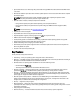
Component Firmware Configuration Security Information* FC HBA Yes Yes NA Enclosure NA NA NA PCIe SSD Yes NA NA * The security information refers to the user credentials that are used to access the components.
NOTE: You can check the Lifecycle logs in iDRAC Web interface for backup server profile status. To view the log in Lifecycle Controller after the backup is completed, click Lifecycle Log → View Lifecycle Log History. System or Feature Behavior During Backup • Lifecycle Controller is disabled. • A partition with a label name SRVCNF is automatically created on the vFlash SD card to store the backup image file. If a partition with the label name SRVCNF already exists, it is overwritten.
• After a successful export, the event is logged in the Lifecycle Log. Import Server Profile Use this feature to apply a backup to the system from which it was taken previously, and restore the system hardware and firmware configuration according to the information stored in the backup image file. For more information about the supported components, see Supported Components.
– 5. Delete configuration — Deletes the RAID level, virtual drive, and controller attributes. If you have secured the backup image file with a passphrase, enter the passphrase (entered during backup) in the Backup File Passphrase box, and then click Finish. Related Links System or Feature Behavior During Import Import Server Profile Importing Server Profile After Motherboard Replacement Network Share To import from a network share: 1. In the left pane, select Platform Restore. 2.
System or Feature Behavior During Import • Lifecycle Controller is not available during restore, and is enabled after the import operation is complete. • Restores everything that was backed up, including Lifecycle controller content. • Import may take up to 45 minutes depending on the server configuration. • Diagnostics or driver pack information is not restored.
Import Server License Use this feature to import an iDRAC license from the Lifecycle Controller GUI. The scenarios in which you may want to import a license are when you set up a new server shipped from the factory, while upgrading an Express license to an Enterprise license, and so on. You can import the license that is stored on a USB drive or on the network share such as CIFS or NFS.
Importing iDRAC License from USB Drive To import a server license from a USB Drive: 1. In the left pane, click Platform Restore. 2. In the right pane, click Import Server License. 3. On the Import Server License page, click USB Drive and click Next. NOTE: If a USB Drive is not connected, the following messages is shown. Insert Media 4. Else, if a USB Drive is connected, click Next. For information about the fields, click the Help link in the upper-right corner of this page.
– Apply always — The feature is enabled and the current configuration is applied if a part is replaced. NOTE: This is the default setting. – Apply only if firmware match — The feature is enabled and the current configuration is applied only if the current firmware matches with the firmware of a replaced part. Supported Devices You can update the part firmware and configuration for the following devices: NOTE: Only part firmware updates are supported on SAS cards and power supply units.
Deleting Configuration and Resetting Defaults You can delete the current iDRAC settings and reset iDRAC to factory-default settings. This feature also deletes Lifecycle logs.
When the tests are complete, results of the diagnostics tests are displayed on the screen. To resolve the problems reported in the test results, search the resolutions at support.dell.com. To close the Hardware Diagnostics page, restart the system, and then press to reenter Lifecycle Controller.
8 Troubleshooting and Frequently Asked Questions This section describes the error messages commonly generated by Lifecycle Controller and provides suggestions for resolving the issues. This section also lists the questions that are frequently asked by Lifecycle Controller users. Error Messages Each error message that is generated from Lifecycle Controller has a Message ID, Message Description, and Recommended Response Action in a single dialog box.
9. Can I delete Lifecycle Controller? No. 10. Can I use virtual media for the operating system media source during installation? Yes. For more information about iDRAC, see the iDRAC7 User’s Guide available at dell.com/support/manuals. 11. Can I use a virtual USB Drive for my update repository? Yes. For more information, see the iDRAC7 User’s Guide available at dell.com/support/manuals. 12.
The features like Lifecycle Log, Hardware Inventory (View and Export), Part Replacement, and vFlash SD card configuration depends on latest iDRAC firmware. Make sure that the latest iDRAC firmware is installed.
Lifecycle Log Schema 9 To view a typical lifecycle log schema, go to http://en.community.dell.com/techcenter/extras/m/white_papers/ 20270305.aspx.
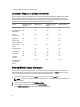
Easy-to-use System Component Names 10 The following table lists the Fully Qualified Device Descriptor (FQDD) of the system components and the equivalent easyto-use names. Table 6. Easy-to-use Names of System Components FQDD of System Component Name Easy-to-use Name RAID.Integrated.1-1 Integrated RAID Controller 1 RAID.Slot.1-1 RAID Controller in Slot 1 NIC.Mezzanine.1B-1 NIC in Mezzanine NIC.Mezzanine.1C-1 NIC.Mezzanine.1C-2 NIC.Mezzanine.3C-2 NonRAID.Integrated.
FQDD of System Component Name Easy-to-use Name Optical.USBFront.1-1 Optical drive connected to front USB 1 Disk.USBInternal.1 Disk connected to Internal USB 1 Optical.iDRACVirtual.1-1 Virtually connected optical drive Floppy.iDRACVirtual.1-1 Virtually connected floppy drive Disk.iDRACVirtual.1-1 Virtually connected disk Floppy.vFlash. vFlash SD Card Partition 2 Disk.vFlash. vFlash SD Card Partition 3 iDRAC.Embedded.1-1 iDRAC System.Embedded.1-1 System HardDisk.List.
Using The System Setup and Boot Manager 11 System Setup enables you to manage your system hardware and specify BIOS-level options. The following keystrokes provide access to system features during startup: Keystroke Description Opens the System Setup page. Enters System Services and starts Lifecycle Controller which supports systems management features such as operating system deployment, hardware diagnostics, firmware updates, and platform configuration, using a graphical user interface.
• UEFI boot mode is an enhanced 64-bit boot interface based on Unified Extensible Firmware Interface (UEFI) specifications that overlays the system BIOS. You must select the boot mode in the Boot Mode field of the Boot Settings screen of System Setup. Once you specify the boot mode, the system boots in the specified boot mode and you then proceed to install your operating system from that mode.
System Setup Options System Setup Main Screen NOTE: Press to reset the BIOS or UEFI settings to their default settings. Menu Item Description System BIOS This option is used to view and configure BIOS settings. iDRAC Settings This option is used to view and configure iDRAC settings. Device Settings This option is used to view and configure device settings. System BIOS Screen NOTE: The options for System Setup change based on the system configuration.
System Information Screen Menu Item Description System Model Name Displays the system model name. System BIOS Version Displays the BIOS version installed on the system. System Service Tag Displays the system Service Tag. System Manufacturer Displays the name of the system manufacturer. System Manufacturer Displays the contact information of the system manufacturer.
Processor Settings Screen Menu Item Description Logical Processor Allows you to enable or disable logical processors and display the number of logical processors. If the Logical Processor option is set to Enabled, the BIOS displays all the logical processors. If this option is set to Disabled, the BIOS only displays one logical processor per core. By default, the Logical Processor option is set to Enabled. QPI Speed Allows you to set the QuickPath Interconnect (QPI) data rate settings.
Menu Item Description Processor 1 NOTE: The following settings are displayed for each processor installed in the system. Family-ModelStepping Displays the family, model and stepping of the processor as defined by Intel. Brand Displays the brand name reported by the processor. Level 2 Cache Displays the total L2 cache. Level 3 Cache Displays the total L3 cache. Number of Cores Displays the number of cores per processor.
Menu Item Description NOTE: Setting this field to UEFI disables BIOS Boot Settings menu. Setting this field to BIOS disables the UEFI Boot Settings menu. Boot Sequence Retry Allows you to enable or disable the boot sequence retry feature. If this field is enabled and the system fails to boot, the system reattempts the boot sequence after 30 seconds. By default, the Boot Sequence Retry option is set to Disabled. BIOS Boot Settings Allows you to enable or disable BIOS Boot options.
Menu Item Description SR-IOV Global Enable Allows you to enable or disable the BIOS configuration of Single Root I/O Virtualization (SRIOV) devices. By default, the SR-IOV Global Enable option is set to Disabled. Memory Mapped I/O above 4GB Allows you to enable support for PCIe devices that require large amounts of memory. By default, the option is set to Enabled. Slot Disablement Allows you to enable or disable available PCIe slots on your system.
Menu Item Description NOTE: The following parameters are available only when the System Profile is set to Custom. CPU Power Management Allows you to set the CPU power management. By default, the CPU Power Management option is set to System DBPM (DAPC). DBPM is Demand-Based Power Management. Memory Frequency Allows you to set the memory frequency. By default, the Memory Frequency option is set to Maximum Performance.
Menu Item Description TPM Security Allows you to control the reporting mode of the Trusted Platform Module (TPM). By default, the TPM Security option is set to Off. You can only modify the TPM Status, TPM Activation , and Intel TXT fields if the TPM Status field is set to either On with Pre-boot Measurements or On without Pre-boot Measurements. TPM Activation Allows you to change the operational state of the TPM. By default, the TPM Activation option is set to No Change.
Menu Item Description Report Keyboard Errors Allows you to set whether keyboard-related error messages are reported during system boot. By default, the Report Keyboard Errors option is set to Report. F1/F2 Prompt on Error Allows you to enable or disable the F1/F2 prompt on error. By default, F1/F2 Prompt on Error is set to Enabled. In-System Characterization This option enables or disables In-System Characterization. By default, In-System Characterization is set to Enabled.
– Only the following special characters are allowed: space, (”), (+), (,), (-), (.), (/), (;), ([), (\), (]), (`). A message prompts you to re-enter the system password. 6. Re-enter the system password that you entered earlier and click OK. 7. Select Setup Password, enter your system password and press or . A message prompts you to re-enter the setup password. 8. Re-enter the setup password that you entered earlier and click OK. 9. Press to return to the System BIOS screen.
NOTE: You can use the Password Status option in conjunction with the System Password and Setup Password options to protect your system from unauthorized changes. Operating With A Setup Password Enabled If Setup Password is Enabled, enter the correct setup password before modifying most of the System Setup options. If you do not enter the correct password in three attempts, the system displays the message Invalid Password! Number of unsuccessful password attempts: System Halted! Must power down.
Key Description NOTE: For the standard graphics browser only. Moves to the previous page till you view the main screen. Pressing in the main screen exits the Boot Manager and proceeds with system boot. Displays the System Setup help file. NOTE: For most of the options, any changes that you make are recorded but do not take effect until you restart the system.
iDRAC Settings Utility The iDRAC Settings utility is an interface to setup and configure the iDRAC parameters using UEFI. You can enable or disable various iDRAC parameters using the iDRAC Settings Utility. NOTE: Accessing some of the features on the iDRAC Settings Utility requires the iDRAC7 Enterprise License upgrade. For more information on using iDRAC, see the iDRAC7 User's Guide at dell.com/esmmanuals. Entering The iDRAC Settings Utility 1. Turn on or restart the managed system. 2.