Dell Lifecycle Controller 2 Release 1.4.
Notes, Cautions, and Warnings NOTE: A NOTE indicates important information that helps you make better use of your computer. CAUTION: A CAUTION indicates either potential damage to hardware or loss of data and tells you how to avoid the problem. WARNING: A WARNING indicates a potential for property damage, personal injury, or death. Copyright © 2014 Dell Inc. All rights reserved. This product is protected by U.S. and international copyright and intellectual property laws.
Contents 1 Introduction................................................................................................................7 Why Use Lifecycle Controller................................................................................................................7 Benefits of Using iDRAC7 with Lifecycle Controller............................................................................ 8 What's New in this Release?.............................................................................
Hardware Inventory View and Export.................................................................................................25 About View and Export Current Inventory......................................................................................... 25 About View and Export Factory-Shipped Inventory.......................................................................... 25 Viewing Hardware Inventory—Current or Factory-Shipped.............................................................
Applying the Local Key On RAID Controller................................................................................. 51 Local Key Encryption Mode................................................................................................................ 52 Encrypting Unsecure Virtual Disks................................................................................................52 Rekey Controller With New Local Key..............................................................................
Hardware Diagnostics.........................................................................................................................70 Performing Hardware Diagnostics............................................................................................... 70 8 Troubleshooting and Frequently Asked Questions....................................... 71 Error Messages....................................................................................................................................
Introduction 1 The Dell Lifecycle Controller provides advanced embedded systems management to perform systems management tasks such as deploy, configure, update, maintain, and diagnose through a graphical user interface. It is delivered as part of iDRAC7 out-of-band solution and embedded Unified Extensible Firmware Interface (UEFI) applications in the latest Dell servers.
Benefits of Using iDRAC7 with Lifecycle Controller The benefits include: • Increased Availability — Early notification of potential or actual failures that help prevent a server failure or reduce recovery time after failure. • Improved Productivity and Lower Total Cost of Ownership (TCO) — Extending the reach of administrators to larger numbers of distant servers can make IT staff more productive while driving down operational costs such as travel.
• Restoring Platform — Backup the server profile (including RAID configuration) and restore the server to a previously-known state. Importing a server license, updating firmware, and restoring system configuration in case of motherboard replacement. • Lifecycle logs for troubleshooting • Hardware inventory — Provides information about both the current and factory system configuration. • Supports H730P controller on the Equinox server.
About symbol in the upper-right corner of Lifecycle Controller GUI. To view information about an iDRAC license: 1. On any page of Lifecycle Controller, click About in the upper-right corner. On the About page: NOTE: If a license is not installed on the server, information such as entitlement ID and license expiration are not displayed. 2. 3. To read through the Release Notes, click View Release Notes. To view detailed information about iDRAC, click License Information.
• The PERC H710, H710P, and H810 Technical Guidebook for specification and configuration-related information about the PERC H710, H710P, and H810 controllers. • The Glossary provides information about the terms used in this document. • The Dell OpenManage Server Update Utility User's Guide provides information about using the DVD– based application for identifying and applying updates to the system.
* Client System Management * Enterprise System Management * Remote Enterprise System Management * Serviceability Tools – To view the document, click the required product version. • Using search engines as follows: – Type the name and version of the document in the Search box. Contacting Dell NOTE: If you do not have an active Internet connection, you can find contact information on your purchase invoice, packing slip, bill, or Dell product catalog.
Using Lifecycle Controller 2 This section provides information about launching Lifecycle Controller, enabling or disabling it, and launching it for the first time. Before using Lifecycle Controller, make sure that the network and iDRAC7 are configured. For more information, see iDRAC7 User’s Guide. Launching Lifecycle Controller To start Lifecycle Controller during the system start, press thekey within 10 seconds after the manufacturer's or service provider’s logo is displayed.
Restoring a Server Profile from vFlash Backup When you have a backup on a vFlash SD card, but a service tag is not available: 1. Lifecycle Controller automatically displays the following message on the home page. Click Yes. Do you want to restore the service tag? 2. In the Restore Service Tag dialog box: – To import a server profile that is stored on a vFlash SD card, click Import Server Profile. For more information about importing a server profile, see Import Server Profile.
Message Cause Resolution information about DUPs, see the Dell Update Packages User’s Guide available at dell.com/support/ manuals. For more information about recovering Lifecycle Controller from the Lifecycle Controller Update Required mode, see the Recovery from ‘Lifecycle Controller Update Required’ white paper available at delltechcenter.com/lc. Lifecycle Controller not available Another process is currently using iDRAC.
Canceling Lifecycle Controller Actions If Lifecycle Controller causes the system to restart twice, cancel the Lifecycle Controller actions. However, if Lifecycle Controller causes the system to restart the third time, the message LC Update required is displayed, and you must use Lifecycle Controller repair package to recover Lifecycle Controller. CAUTION: This action cancels all tasks that are being performed by Lifecycle Controller.
Configuring Network Settings for a NIC 1. In the left pane, click Settings. 2. In the right pane, click Network Settings. 3. From the NIC Card drop-down menu, select the NIC card that you want to configure. You can use only one NIC at a time to communicate with the network. 4. From the IP Address Source drop-down menu, select one of the following options: NOTE: The IP Address Source function supports only IPv4.
Lifecycle Controller Features This section provides a brief description about the Lifecycle Controller features and helps know about the wizards to use Lifecycle Controller most effectively. Each feature is a wizard in Lifecycle Controller, which supports the following features: • Home — Navigate back to the Home page. • Lifecycle Log — View and export lifecycle log, and add a work note to lifecycle log.
Operating System Deployment 3 Using the operating system deployment wizard, you can deploy various custom and standard operating systems on the managed system and configure a RAID during installation. Related Links Installing Operating System Installing Operating System in Unattended Mode Installing Operating System Before installing an operating system (OS), make sure that the following prerequisites are met: • Optical DVD drive, or a virtual media (ISO image) is connected virtually to a server.
5. Select the deployment mode, insert the operating system media, and then complete the remaining tasks. NOTE: If you select an operating system that supports UEFI boot mode, BIOS and UEFI options are provided for selecting the boot mode. 6. Restart the system. The operating system is automatically installed on the selected virtual disk.
Selecting an Operating System Available in the List To install an operating system that is available in the list: 1. From the list, select the required operating system, and then click Next. The drivers are extracted to the OEMDRV directory, and Lifecycle Controller prompts you to insert the operating system installation media. 2. Lifecycle Controller displays two installation modes — UEFI or BIOS. Select one of the options and click Next.
Driver Access Driver Access Lifecycle Controller provides a local repository for drivers that are required for installing the operating system. On the basis of operating system being installed, the OS Deployment wizard extracts these drivers and copies them to a temporary directory on the managed system.
Post-reboot Scenarios The following table lists the post-reboot scenarios, its user actions, and impact. Scenario User Action and Impact During POST, the system prompts you to press a key to boot into the operating system installation media Press any key to begin the operating system installation; else, the system boots to the hard disk drive and not the operating system installation media. Operating system installation is interrupted and the system restars before the installation is completed.
Monitor 4 Using Lifecycle Controller, you can monitor the hardware inventory and events in the system throughout its lifecycle.
Viewing Hardware Inventory—Current or Factory-Shipped Exporting Hardware Inventory—Current or Factory-Shipped Viewing Hardware Inventory—Current or FactoryShipped To view the currently-installed or factory-installed hardware components and their configuration details: NOTE: For factory-shipped inventory, the state of few parameters for the installed components is displayed as Unknown. 1. In the left pane, click Hardware Configuration. 2. In the right pane, click Hardware Inventory. 3.
5. To verify whether or not Lifecycle Controller is able to connect to the IP address that you entered, click Test Network Connection. By default, Lifecycle Controller PINGs the Gateway IP, DNS server IP, and the host IP. NOTE: If the DNS is not able to resolve the domain name, Lifecycle Controller cannot ping to the domain name and does not display its IP address. Make sure that the DNS–related issue is resolved, and then retry the operation. 6. Click Finish to export the inventory.
• Share Name — Type the path to the shared folder where you must store the file. For example, \ \xxx.xxx.xx.xx\sharename. • File Path — Type the sub-directories, if any. For example, 2011\Nov. NOTE: Lifecycle Controller allows 256 characters in a path, and does not support special characters such as :, *, ?, ", <, >, |, #, %, and ^ in folder names. Viewing or Exporting Hardware Inventory After Part Replacement To view or export the hardware inventory after part replacement: 1.
Lifecycle Log Lifecycle Controller provides the history of firmware changes of the related components installed on a managed system. Using this wizard, you can view and export lifecycle log, and add a work note to a log history. The log contains the following: • Firmware update history on the basis of device, version, and date and time. • Events on the basis of category, severity, and date and time. • User comments history on the basis of date and time.
To view the Lifecycle Log history and use the filtering options: 1. In the left pane, click Lifecycle Log. 2. In the right pane, click View Lifecycle Log History. – No. — The serial number of the event. – Category — The category to which the events belong to. The available categories are: * System Health — Events related to installed hardware such as fan, PSUs, NIC/LOM/CNA link, BIOS errors, and so on.
3. Select either USB Drive or Network Share. 4. If you select the Network Share option, click Test Network Connection to verify if Lifecycle Controller is able to connect to the IP address that you provided. By default, it pings the Gateway IP, DNS server IP, and host IP. NOTE: Lifecycle Controller cannot ping to the domain name and does not display its IP address if the DNS is not able to resolve the domain name. Make sure that the issue with DNS is resolved and retry. 5. Click Finish.
5 Firmware Update Using Lifecycle Controller, the system can be updated using the repositories accessible through FTP or located on a locally-attached USB drive, DVD, or network share. Use the Firmware Update page to: • View the current version of the installed applications and firmware. • View a list of available updates. • Select the required updates, downloads (automatic), and then apply the updates for the following components listed in the table.
** When iDRAC7 is updated from version 1.30.30 or later, a system restart is not necessary. However, firmware versions of iDRAC7 earlier than 1.30.30 require a system restart when applied using the out-ofband interfaces.
NOTE: Make sure that the file name for the single component DUPs does not have any blank space. NOTE: If Collect System Inventory On Restart (CSIOR) is disabled while performing an update, Lifecycle Controller automatically updates the system inventory. NOTE: Both 32–bit and 64–bit DUPs and catalog are supported. NOTE: During BIOS update, due to security reasons, the progress bar stops at 40 seconds, jumps to 1 minute 50 seconds after a while, and then completes. To update the firmware: 1.
Selecting and Applying Updates Updating or Rolling Back Devices That Affect Trusted Platform Module Settings Selecting Type of Update And Update Source To perform the updates, you can download single component DUPs or repository (Catalog.xml) using the Firmware Update wizard to one of the following: NOTE: The Catalog.xml file contains the individual server bundles. Each bundle consists of all the DUP information (md5 security key, date and time, path, Release ID, version, and so on.
3. In the File Path or Update package path box, enter the location or sub-directory where the catalog is stored. NOTE: If the catalog file is located in the root folder, do not enter the file name in the File Path or Update package path box. However, if the catalog file is located in a sub-directory, enter the sub-directory name (for example, subdirectory). NOTE: If the catalog file or DUP is downloaded from ftp.dell.com, do not copy them into a sub-directory.
Using Non-Proxy FTP Server Lifecycle Controller can access the latest firmware from ftp.dell.com. It downloads the DUPs from this location to perform firmware update. Before performing an update, make sure the following prerequisites are met: • The network settings are configured (Settings → Network Settings). • The updates are downloaded using Dell Repository Manager, and the repository is created on an internal FTP server.
NOTE: If the catalog file is located in the root folder, do not enter the file name in the File Path or Update package path box. However, if the catalog file is located in a sub-directory, enter the sub-directory name (for example, subdirectory). NOTE: If the catalog file or DUP is downloaded from ftp.dell.com, do not copy them into a sub-directory. NOTE: Lifecycle Controller allows 256 characters in a path, and does not support special characters such as :, *, ?, ", <, >, |, #, %, and ^ in folder names.
NOTE: Make sure that the file name for the single component DUPs does not have any blank space. NOTE: Both 32–bit and 64–bit DUPs are supported. In the File Path or Update package path box, enter the name of the DUP (for example, APP_WIN_RYYYZZZ.EXE) or if the DUP is present in a sub-directory, enter both the sub-directory name and name of the DUP (for example, subdirectory\APP_WIN_RYYYZZZ.EXE).
Rolling Back to Previous Firmware Versions Rolling Back to Previous Firmware Versions You can roll back to earlier versions of a firmware using the Firmware Rollback wizard. NOTE: If you update any firmware only once, the rollback feature provides the option to revert to the factory-installed component firmware image. If you update the firmware more than once, the factory‑installed images are overwritten and you cannot revert to them. To roll back a firmware: 1. In the left pane, click Firmware Update.
Configure 6 Lifecycle Controller provides various system configuration wizards. Use the configuration wizards to configure system devices. The Configuration Wizards has: • System Configuration Wizards — This includes LCD Panel Security, iDRAC Settings, System Date and Time Configuration, and vFlash SD card Configuration. • Storage Configuration Wizards — This includes RAID Configuration, Key Encryption, and Break Mirror.
5. Click Finish to apply the changes. Configuring iDRAC To configure iDRAC parameters applicable to the system, such as LAN, common IP settings, IPv4, IPv6, Virtual Media, and LAN user configuration use the iDRAC Settings wizard. NOTE: You can also use the System Setup utility during startup for configuring iDRAC. For more information about the System Setup utility, see the Using The System Setup Program And Boot Manager chapter in this User's Guide. To configure and manage the iDRAC parameters: 1.
Configuring vFlash SD Card Use the licensed feature to enable or disable the vFlash SD card, check the health and properties, and initialize the vFlash SD card. Lifecycle Controller support vFlash SD cards of sizes 1 GB, 2 GB, 8 GB, 16 GB, and 32 GB. NOTE: The options under vFlash SD card are grayed-out if there is no SD card inserted in the slot. See the Integrated Dell Remote Access Controller 7 (iDRAC7) User’s Guide available at dell.
Configuring RAID If your system has one or more supported PERC RAID controllers with PERC 8 firmware or later, or SAS RAID controllers, use the RAID Configuration wizard to configure a virtual disk as the boot device. NOTE: If there are any internal storage controller cards on the system, all other external cards cannot be configured. If there are no internal cards, then external cards can be configured. To configure RAID: 1. In the left pane, click Hardware Configuration. 2.
• To delete all data on the physical disk drives containing the foreign configuration, click Clear Foreign Configuration. This option deletes the hard disk drive space containing the foreign configuration and makes it available for use in a new virtual drive. After selecting one of the options, click Next.
physical disk is rebuilding in one RAID 6 set do not lead to data loss. RAID 60 has improved fault tolerance because more than two physical disks on either span must fail for data loss to occur. Minimum Disk Requirement for Different RAID Levels Table 4. : RAID Level and Number of Disks RAID Level Minimum Number of Disks 0 1* 1 2 5 3 6 4 10 4 50 6 60 8 * For S110 RAID controller, a minimum of two hard disk drives are required.
contain more options than initially displayed on the screen. Use the UP ARROW and DOWN ARROW keys to view all available options. • Read Policy — Select the read policy: – Read Ahead — The controller reads sequential sectors of the virtual drives when seeking data. The Read Ahead policy may improve system performance if the data is written to sequential sectors of the virtual drives. – No Read Ahead — The controller does not use the Read Ahead policy.
NOTE: For more information about RAID configuration, see the How to create RAID using Lifecycle Controller white paper available at delltechcenter.com/lc. NOTE: If you have an older BIOS, you can configure RAID only through Option ROM. Use this feature to configure RAID if a PERC S110 controller is enabled on the system. If the software RAID option is selected, Lifecycle Controller displays the physical disk drives as Non-RAID disks or RAIDready disks.
3. Under Storage Configuration Wizards, click RAID Configuration to launch the wizard. The View Current RAID Configuration and Select Controller page is displayed along with the information on whether or not the displayed virtual disk is secure. 4. Select the controller and click Next. If the non-RAID disks are attached to the selected controller, select the non-RAID physical disk drives, and then click Next to initialize them. Else, the Select RAID Level page is displayed.
3. Under Storage Configuration wizards, click Key Encryption. 4. Select the controller to apply a local key and click Next. 5. Click Set up local key encryption and click Next. NOTE: Some controller options are disabled if they do not support encryption. 6. Enter the Encryption Key Identifier that is associated with the entered passphrase. The Encryption Key Identifier is a passphrase hint; you must enter the passphrase when Lifecycle Controller prompts with this hint. 7.
4. Select the controller that is encrypted and click Next. NOTE: The encryption mode (Local Key Encryption) applied to the selected controller does not change. 5. Select Encrypt unsecure virtual disks and click Next. 6. To enable encryption, select the unsecure virtual drives and click Finish. Related Links Local Key Encryption Mode Rekey Controller With New Local Key To rekey the controller with a new local key: 1. In the left pane, click Hardware Configuration. 2.
4. Select the related controller and click Finish. NOTE: Break Mirror feature does not support software RAID controllers. NOTE: For more information about the Break-mirror feature, see the Performing a Break-Mirror Operation Using white paper available at delltechcenter.com/lc. The system automatically turns off even if one mirrored array is successfully delinked.
– Intel i350 DP 1G ADAPTER (Low Profile) – Intel i350 QP 1G ADAPTER (Full Height) – Intel i350 QP 1G ADAPTER (Low Profile) – Intel i540 QP rNDC (10G BASE-T + 1G BASE-T) – Intel i350 QP rNDC 1G BASE-T – Intel i520 DP bNDC KR – Intel DP 10Gb KR Mezz – Intel DP 10Gb KR Mezz – Intel I350 QP 1G Mezz – ConnectX-3 Dual Port 10 GbE KR Blade Mezzanine Card – ConnectX-3 Dual Port 10 GbE DA/SFP+ Network Adapter – ConnectX-3 Dual Port 40 GbE QSFP+ Network Adapter – Fibre Channel cards: * QLogic QLE2660 Single Port FC1
Integrated Broadcom NICs are controlled by both BIOS and the settings stored on the device itself. As a result, the Boot Protocol field in the HII of integrated NICs has no effect; this setting is instead controlled by the BIOS on the Integrated Devices screen. To set integrated NICs to an iSCSI or PXE boot mode, select System BIOS Settings, and then select Integrated Devices.
FTP Authentication Although you must provide the user name and password for the FTP server, Lifecycle Controller supports anonymous login to the FTP server using the FTP server address to download the catalog information. If you use a firewall, you should configure it to allow outgoing FTP traffic on port 21. The firewall must be configured to accept incoming FTP response traffic. Requirements for a Local FTP Server The following requirements apply when configuring a local FTP server.
– Address — The IP address of the local FTP server or ftp.dell.com – User Name — The user name to access the FTP location. – Password — The password to access this FTP location. – Proxy Server — The server host name or the IP address of the proxy server. – Proxy Port — The port number of the proxy server. – Proxy Type — The type of proxy server. HTTP and SOCKS 4 proxy types are supported by Lifecycle Controller. – Proxy User Name — The user name required for authentication on the proxy server.
Maintain 7 Using Lifecycle Controller, you can maintain the health of a system throughout its lifecycle by using the features such as Part Replacement Configuration and Platform Restore. Platform Restore Lifecycle Controller allows you to create a copy (image file) of the server's profile on the vFlash SD card attached to the server.
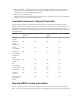
– Component certificates – Licenses – Signature to validate that backup file is not been tampered and was generated by Lifecycle Controller The server profile backup image file does not contain: • Operating system or any data stored on hard disk drives or virtual drives • vFlash SD card partition information • Lifecycle log • Dell diagnostics • Dell OS Driver Pack • A Local Key Management (LKM) passphrase, if the LKM–based storage encryption is enabled.
Component Firmware Configuration Security Information* Backplane NA NA NA CPLD NA NA NA Power Supply Yes NA NA FC HBA Yes Yes NA Enclosure NA NA NA PCIe SSD Yes NA NA * The security information refers to the user credentials that are used to access the components.
4. In the Backup File Passphrase field, enter a passphrase. For example, Rt@#12tv. NOTE: A valid passphrase contains 8 to 32 characters. It must include a combination of uppercase and lowercase letters, numbers, symbols, and must not have white spaces. The passphrase is optional and if used for backup, it must be used during restore. 5. In the Confirm Passphrase box, reenter the passphrase and click Finish. The system restarts and Lifecycle Controller is disabled.
3. Select either USB Drive or Network Share, enter the details, and then click Finish. NOTE: You can also use a USB drive that is attached to the client system while operating remotely. To do this, use the Virtual Media feature. For more information, see iDRAC User’s Guide. The Backup__.img file is exported to the specified location. Related Links USB Drive Network Share System or Feature Behavior during Export • Takes up to five minutes on the basis of a server configuration.
You can import the server profile from a vFlash SD card, Network Share, or a USB drive. Related Links System or Feature Behavior During Import vFlash SD Card Network Share USB Drive Post-import Scenario Import Server Profile vFlash SD Card To import from a vFlash SD card: 1. In the left pane, select Platform Restore. 2. In the right pane, select Import Server Profile. 3. Select vFlash Secure Digital (SD) Card and click Next. 4. Select either Preserve configuration or Delete Configuration.
USB Drive To import from a USB drive: 1. In the left pane, select Platform Restore. 2. In the right pane, select Import Server Profile. 3. Select USB Drive and click Next. 4. From the Select Device drop-down menu, select the attached USB drive. 5. In the File Location text box, enter the directory or sub-directory path, where the backup image file is stored on the selected device. 6. Select either Preserve configuration or Delete Configuration. 7.
Importing Server Profile from a vFlash SD Card Network Share or USB Drive Importing Server Profile After Motherboard Replacement Before importing the server profile after motherboard replacement, make sure that the following prerequisites are met: • A backup image of the server with the old motherboard is present. • If you are restoring from a vFlash SD card, it must be installed, and contain the backup image in a folder labeled SRVCNF.
• If importing a leased license, that date of import must be a date after the lease date is activated. Importing iDRAC License from Network Share To import a server license from a network share: 1. In the left pane, click Platform Restore. 2. In the right pane, click Import Server License. 3. On the Import Server License page, click Network Share and click Next. NOTE: If a network is not configured, the following messages is shown. Network is not configured. Do you want to configure now? 4.
NOTE: If Collect System Inventory On Restart is disabled, the cache of system inventory information may become stale if new components are added without manually entering Lifecycle Controller after turning the system on. In the manual mode, you must press the key after part replacement during a system restart. • Make sure that the Disabled option under Part Firmware Update and Part Configuration Update are cleared.
Repairing Lifecycle Controller If the message Lifecycle Controller update required appears during power-on self-test (POST), the embedded device that stores Lifecycle Controller may contain corrupted data. To resolve the issue, you must first attempt to update Lifecycle Controller by executing Lifecycle Controller Dell Update Package (DUP) from OS. For more information, see the Dell Update Packages User’s Guide available at dell.com/support/manuals.
To delete configuration and reset to factory default settings: 1. In the left pane, click Hardware Configuration. 2. In the right pane, click Delete Configuration and Reset Defaults. 3. Select Reset Lifecycle Controller. 4. Click Finish. A message is displayed. 5. Click Yes to continue or No to cancel the operation. The system automatically turns off. The system must be manually turned on either by using the Virtual Console or by pressing the power button on the system.
Troubleshooting and Frequently Asked Questions 8 This section describes the error messages commonly generated by Lifecycle Controller and provides suggestions for resolving the issues. This section also lists the questions that are frequently asked by Lifecycle Controller users. Error Messages Each error message that is generated from Lifecycle Controller has a Message ID, Message Description, and Recommended Response Action in a single dialog box.
7. Can I update the drivers used by an already-installed operating system through Lifecycle Controller? No. Lifecycle Controller only provides drivers that are required for operating system installation. To update the drivers used by an installed operating system, see your operating system’s Help documentation. 8. Can I add my own drivers and firmware for updating Lifecycle Controller to a local USB drive? No. Only drivers and firmware downloaded from the Dell Server Updates DVD is supported.
18. How do I find out the currently-installed version details of the Lifecycle Controller product? Click About in the left navigation pane. 19. What should I do if I have an issue with mouse cursor synchronization when I access Lifecycle Controller through the iDRAC Virtual Console? Make sure that the Single Cursor option under Tools menu in the iDRAC Virtual Console is selected on the iDRAC Virtual Console client.
Lifecycle Log Schema 9 To view a typical lifecycle log schema, go to http://en.community.dell.com/techcenter/extras/m/ white_papers/20270305.aspx.
10 Easy-to-use System Component Names The following table lists the Fully Qualified Device Descriptor (FQDD) of the system components and the equivalent easy-to-use names. Table 6. Easy-to-use Names of System Components FQDD of System Component Name Easy-to-use Name RAID.Integrated.1-1 Integrated RAID Controller 1 RAID.Slot.1-1 RAID Controller in Slot 1 NIC.Mezzanine.1B-1 NIC in Mezzanine NIC.Mezzanine.1C-1 NIC.Mezzanine.1C-2 NIC.Mezzanine.3C-2 NonRAID.Integrated.
FQDD of System Component Name Easy-to-use Name Optical.USBFront.1-1 Optical drive connected to front USB 1 Disk.USBInternal.1 Disk connected to Internal USB 1 Optical.iDRACVirtual.1-1 Virtually connected optical drive Floppy.iDRACVirtual.1-1 Virtually connected floppy drive Disk.iDRACVirtual.1-1 Virtually connected disk Floppy.vFlash. vFlash SD Card Partition 2 Disk.vFlash. vFlash SD Card Partition 3 iDRAC.Embedded.1-1 iDRAC System.Embedded.1-1 System HardDisk.List.
Using The System Setup and Boot Manager 11 System Setup enables you to manage your system hardware and specify BIOS-level options. The following keystrokes provide access to system features during startup: Keystroke Description Opens the System Setup page. Enters System Services and starts Lifecycle Controller, which supports systems management features such as operating system deployment, hardware diagnostics, firmware updates, and platform configuration, using a graphical user interface.
• BIOS boot mode (the default) is the standard BIOS-level boot interface. • UEFI boot mode is an enhanced 64-bit boot interface based on Unified Extensible Firmware Interface (UEFI) specifications that overlays the system BIOS. You must select the boot mode in the Boot Mode field of the Boot Settings screen of System Setup. Once you specify the boot mode, the system boots in the specified boot mode and you then proceed to install your operating system from that mode.
NOTE: For most of the options, any changes that you make are recorded but do not take effect until you restart the system. System Setup Options System Setup Main Screen NOTE: Press to reset the BIOS or UEFI settings to their default settings. Menu Item Description System BIOS This option is used to view and configure BIOS settings. iDRAC Settings This option is used to view and configure iDRAC settings. Device Settings This option is used to view and configure device settings.
Menu Item Description Miscellaneous Settings Displays options to change the system date, time, and so on. System Information Screen Menu Item Description System Model Name Displays the system model name. System BIOS Version Displays the BIOS version installed on the system. System Service Tag Displays the system Service Tag. System Manufacturer Displays the name of the system manufacturer. System Manufacturer Contact Information Displays the contact information of the system manufacturer.
Menu Item Description NOTE: The Dell Fault Resilient Mode establishes an area of memory that is fault resilient. This mode can be used by an operating system that supports the feature to load critical applications or enables the operating system kernel to maximize system availability. Node Interleaving If this field is Enabled, memory interleaving is supported if a symmetric memory configuration is installed.
Menu Item Description Logical Processor Idling Allows you to enable or disable the OS capability to put logical processors in the idling state in order to reduce power consumption. By default, the option is set to Disabled. Number of Cores per Processor Allows you to control the number of enabled cores in each processor. By default, the Number of Cores per Processor option is set to All. Processor 64-bit Support Specifies if the processor(s) support 64-bit extensions.
Menu Item Description Port F Auto enables BIOS support for the device attached to SATA port F. By default, Port F is set to Auto. NOTE: Ports A, B, C, and D are used for the backplane drives, port E for the optical drive (CD/DVD), and port F for the tape drive. Boot Settings Screen Menu Item Description Boot Mode Allows you to set the boot mode of the system. CAUTION: Switching the boot mode may prevent the system from booting if the operating system is not installed in the same boot mode.
Menu Item Description Internal SD Card Port Enables or disables the system’s internal SD card port. By default, the Internal SD Card Port option is set to On. NOTE: This option is displayed only if IDSDM is installed on the system board. Internal SD Card Redundancy If set to Mirror mode, data is written on both SD cards. If any one of the SD card fails, data is written to the active SD card. Data from this card is copied to the replacement SD card at the next boot.
Menu Item Description NOTE: Only Serial Device 2 can be used for Serial Over LAN (SOL). To use console redirection by SOL, configure the same port address for console redirection and the serial device. External Serial Connector Allows you to associate the external serial connector to serial device 1, serial device 2, or remote access device. By default, the External Serial Connector option is set to Serial Device1. NOTE: Only Serial Device 2 can be used for SOL.
Menu Item Description Monitor/Mwait Allows you to enable Monitor/Mwait instructions in the processor. By default, the Monitor/Mwait option is set to Enabled for all system profiles, except Custom. NOTE: This option can be disabled only if the C States option in Custom mode is disabled. NOTE: When C States is enabled in Custom mode, changing the Monitor/ Mwait setting does not impact system power/performance. Memory Patrol Scrub Allows you to set the memory patrol scrub frequency.
Menu Item Description Allows you to clear all the contents of the TPM. By default, the TPM Clear option is set to No. Intel TXT Allows you to enable or disable Intel Trusted Execution Technology (TXT). To enable Intel TXT, Virtualization Technology must be enabled and TPM Security must be Enabled with Pre-boot measurements. By default, the Intel TXT option is set to Off. BIOS Update Control Allows you to update the BIOS using either DOS or UEFI shell-based flash utilities.
Menu Item Description In-System Characterization This option enables or disables In-System Characterization. By default, In-System Characterization is set to Enabled. System And Setup Password Features You can create a system password and a setup password to secure your system. To enable creation of the system and setup password, the password jumper must be set to enabled. For more information on the password jumper settings, see System Board Jumper Settings.
5. Select System Password , enter your system password, and press or . Use the following guidelines to assign the system password: – A password can have up to 32 characters. – The password can contain the numbers 0 through 9. – Only lower case letters are valid, upper case letters are not allowed. – Only the following special characters are allowed: space, (”), (+), (,), (-), (.), (/), (;), ([), (\), (]), (`). A message prompts you to re-enter the system password. 6.
When Password Status is Locked, type the password and press when prompted at reboot. If an incorrect system password is entered, the system displays a message and prompts you to re-enter your password. You have three attempts to enter the correct password. After the third unsuccessful attempt, the system displays an error message that the system has halted and must be powered down. Even after you shut down and restart the system, the error message is displayed until the correct password is entered.
Key Description Down arrow Moves to the next field. Allows you to type in a value in the selected field (if applicable) or follow the link in the field. Spacebar Expands or collapses a drop-down list, if applicable. Moves to the next focus area. NOTE: For the standard graphics browser only. Moves to the previous page till you view the main screen. Pressing in the main screen exits the Boot Manager and proceeds with system boot. Displays the System Setup help file.
Menu Item Description Boot From File Sets a one-time boot option not included in the boot option list. Embedded System Management The Dell Lifecycle Controller provides advanced embedded systems management throughout the server’s lifecycle. The Lifecycle Controller can be started during the boot sequence and can function independently of the operating system. NOTE: Certain platform configurations may not support the full set of features provided by the Lifecycle Controller.