Dell Lifecycle Controller 2 Release 1.4.
Notes, Cautions, and Warnings NOTE: A NOTE indicates important information that helps you make better use of your computer. CAUTION: A CAUTION indicates either potential damage to hardware or loss of data and tells you how to avoid the problem. WARNING: A WARNING indicates a potential for property damage, personal injury, or death. Copyright © 2014 Dell Inc. All rights reserved. This product is protected by U.S. and international copyright and intellectual property laws.
Contents 1 Introduction..................................................................................................................... 7 Why Use Lifecycle Controller.............................................................................................................................................. 7 Benefits of Using iDRAC7 with Lifecycle Controller.............................................................................................................7 What's New in this Release?........
Exporting Hardware Inventory—Current or Factory-Shipped...........................................................................................22 USB Drive...................................................................................................................................................................23 Network Share...........................................................................................................................................................
Collect System Inventory on Restart................................................................................................................................ 46 Updating Server Inventory Information.......................................................................................................................47 Configuring Local FTP Server...........................................................................................................................................
Entering System Setup.....................................................................................................................................................66 Responding To Error Messages.................................................................................................................................. 66 Using The System Setup Navigation Keys..................................................................................................................66 System Setup Options..
1 Introduction The Dell Lifecycle Controller provides advanced embedded systems management to perform systems management tasks such as deploy, configure, update, maintain, and diagnose through a graphical user interface. It is delivered as part of iDRAC7 out-of-band solution and embedded Unified Extensible Firmware Interface (UEFI) applications in the latest Dell servers.
• Enhanced Embedded Management through Lifecycle Controller – Lifecycle Controller provides deployment and simplified serviceability through Lifecycle Controller GUI for local deployment and Remote Services (WS-Management) interfaces for remote deployment integrated with Dell OpenManage Essentials and partner consoles. For more information on iDRAC7, see Integrated Dell Remote Access Controller User’s Guide available at dell.com/support/ manuals.
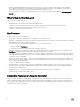
Feature Base Management with IPMI iDRAC7 Express iDRAC7 Express for Blades iDRAC7 Enterprise Firmware Update Yes Yes Yes Yes Operating System Deployment Yes Yes Yes Yes Device Configuration Yes Yes Yes Yes Diagnostics Yes Yes Yes Yes Server Profile Backup and Export — — — Yes Server Profile Import Yes Yes Yes Yes Part Replacement — Yes Yes Yes Local Updates Yes Yes Yes Yes Driver Packs Yes Yes Yes Yes Hardware Inventory Yes Yes Yes Yes Remote Services (th
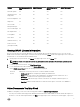
• The Lifecycle Controller Release Notes is available from within the product. To read through the Release Notes within Lifecycle Controller, click the About symbol, and then click View Release Notes. A Web version is also given to provide last-minute updates to the system or documentation or advanced technical reference material intended for experienced users or technicians. • The Dell iDRAC7 Licensing Whitepaper - Differences between iDRAC6 and iDRAC7 at http://en.community.dell.
– For OpenManage Connections Client Systems Management documents — dell.com/OMConnectionsClient • From Dell Support site as follows: – Go to dell.com/support/manuals. – In the Tell us about your Dell system section, under No, select Choose from a list of all Dell products and click Continue. – In the Select your product type section, click Software and Security.
2 Using Lifecycle Controller This section provides information about launching Lifecycle Controller, enabling or disabling it, and launching it for the first time. Before using Lifecycle Controller, make sure that the network and iDRAC7 are configured. For more information, see iDRAC7 User’s Guide. Launching Lifecycle Controller To start Lifecycle Controller during the system start, press thekey within 10 seconds after the manufacturer's or service provider’s logo is displayed.
Restoring System Config by Manually Entering ServiceTag When you do not have a backup on a vFlash SD card: 1. Lifecycle Controller automatically displays the following message on the home page. Click Yes. Unable to Detect Service Tag. Do you want to enter the service tag label? NOTE: Before you restore the system configuration, make sure that the latest version of BIOS is installed. 2. On the Service Tag Settings page, type the service tag, and then click Apply.
The iDRAC Settings page is displayed. 3. Click Lifecycle Controller. 4. Select Enabled. 5. On the System Setup Main Menu page, click Finish to save the settings. 6. Click Yes to restart the system. Disabling Lifecycle Controller To prevent the system from entering Lifecycle Controller during startup: 1. Press within five seconds after system start-up. The System Setup Main Menu page is displayed. 2. Click iDRAC Settings. The iDRAC Settings page is displayed. 3. Click Lifecycle Controller.
Setting Up Lifecycle Controller Use Settings wizard to specify the language, keyboard layout, and network settings for Lifecycle Controller only. This does not change the system or other application settings. Specifying Language and Keyboard Type 1. In the left pane, click Settings. 2. In the right pane, click Language and Keyboard. Use the up-arrow and down-arrow keys to select the options. • 3. From the Language drop-down menu, select the language.
Lifecycle Controller Features This section provides a brief description about the Lifecycle Controller features and helps know about the wizards to use Lifecycle Controller most effectively. Each feature is a wizard in Lifecycle Controller, which supports the following features: • Home — Navigate back to the Home page. • Lifecycle Log — View and export lifecycle log, and add a work note to lifecycle log.
3 Operating System Deployment Using the operating system deployment wizard, you can deploy various custom and standard operating systems on the managed system and configure a RAID during installation. Related links Installing Operating System Installing Operating System in Unattended Mode Installing Operating System Before installing an operating system (OS), make sure that the following prerequisites are met: • Optical DVD drive, or a virtual media (ISO image) is connected virtually to a server.
Related links Selecting Operating System Rebooting System Using Optional RAID Configuration Using Optional RAID Configuration When you install an operating system, you can do one of the following: • Deploy the operating system without configuring RAID. • Configure the hard disk drives using the optional RAID configuration wizard and deploy the operating system.
The Reboot the System page is displayed. Selecting Custom Operating System To install a custom operating system: 1. From the list, select the required custom operating system and click Next. The drivers are extracted into the local directory and Lifecycle Controller prompts you to insert the operating system installation media. 2. Insert the custom operating system media with all the operating system components that are specific to your requirements, and then click Next. 3.
• Unattended Install • Manual Install NOTE: Both the options are displayed only if the OS is compatible for an unattended installation. Else, the Unattended Install option is grayed out, and only the Manual Install option is displayed. 2. On the Select Installation Mode pages, select or enter appropriate data to import an answer file and then click Next.
4 Monitor Using Lifecycle Controller, you can monitor the hardware inventory and events in the system throughout its lifecycle.
Viewing Hardware Inventory—Current or Factory-Shipped To view the currently-installed or factory-installed hardware components and their configuration details: NOTE: For factory-shipped inventory, the state of few parameters for the installed components is displayed as Unknown. 1. In the left pane, click Hardware Configuration. 2. In the right pane, click Hardware Inventory. 3.
Related links About View and Export Current Inventory About View and Export Factory-Shipped Inventory USB Drive Network Share USB Drive To export hardware-related inventory to a USB drive: 1. From the Select Device drop-down menu, select a USB drive. 2. In the File Path box, type a valid directory or sub-directory path on the device. For example, 2011\Nov. If the path is not provided, the file is stored in the root location of the device.
6. To view the latest inventory, on the Hardware Inventory page, click View Current Hardware Inventory to view the latest inventory, or click Export Current Inventory to export the latest inventory to an external location. NOTE: For more information about the part replacement feature, see the Part Replacement in Lifecycle Controller white paper available at delltechcenter.com/lc.
NOTE: As the lifecycle logs are generated by various systems management tools, you may not view the events in lifecycle log immediately after they were logged. To view the Lifecycle Log history and use the filtering options: 1. In the left pane, click Lifecycle Log. 2. In the right pane, click View Lifecycle Log History. • No. — The serial number of the event. • Category — The category to which the events belong to.
5. Click Finish. The Lifecycle Log is exported to the specified location. Related links USB Drive Network Share Adding Work Note to Lifecycle Log Use this feature to record comments that can be used at a later date. For example, scheduled downtime information or for administrators (working in different shifts) to communicate about the changes made by each of them. NOTE: You can type a maximum of 50 characters in the Lifecycle Log field. The special characters such as <, >, &, and % are not supported.
5 Firmware Update Using Lifecycle Controller, the system can be updated using the repositories accessible through FTP or located on a locally-attached USB drive, DVD, or network share. Use the Firmware Update page to: • View the current version of the installed applications and firmware. • View a list of available updates. • Select the required updates, downloads (automatic), and then apply the updates for the following components listed in the table.
Download Methods The following table lists the various locations or media and methods to perform the updates: NOTE: If the FTP server or network share is used for updates, configure the network card using Settings wizard before accessing the updates. Table 2.
5. To verify if Lifecycle Controller is able to connect to the IP address that is provided, click Test Network Connection. By default, it PINGs the Gateway IP, DNS server IP, host IP, and proxy IP (if provided). NOTE: Lifecycle Controller cannot PING to the domain name and does not display its IP address, if the DNS is not able to resolve the domain name. Make sure that the issue with DNS is resolved and retry. 6. Click Next.
Lifecycle Controller automatically detects any necessary updates, and then performs those updates either on components you specifically select. To access the repository on the local drive, create a repository on a DVD or USB drive. Using a DVD Use either Server Update Utility (SUU) DVDs or custom DVDs (SUU ISO downloaded from support.dell.com and written to a DVD) to perform firmware updates.
• Using Proxy FTP Server Related links Accessing Updates on a Local FTP Server Configuring Local USB Drive Using Non-Proxy FTP Server Lifecycle Controller can access the latest firmware from ftp.dell.com. It downloads the DUPs from this location to perform firmware update. Before performing an update, make sure the following prerequisites are met: • The network settings are configured (Settings → Network Settings).
NOTE: If the catalog file or DUP is downloaded from ftp.dell.com, do not copy them into a sub-directory. • • • • • • NOTE: Lifecycle Controller allows 256 characters in a path, and does not support special characters such as :, *, ?, ", <, >, |, #, %, and ^ in folder names. Enable Settings — Select this option to enter the following details: Server — The server host name of the proxy server. Port — The port number of the proxy server.
By default, Lifecycle Controller selects the components for which the current updates are available. For more information, see the Lifecycle Controller online help. 2. Click Apply. The system restarts after the update process is complete. When applying more than one update, the system restarts between updates directly into Lifecycle Controller, and continues with the other selected updates. NOTE: The system does not restart after updating the OS driver pack and hardware diagnostics.
Comparing Firmware Versions To compare the version of the update or rollback with the version currently installed on the system, compare the versions in the Current and Available fields: • Component — Displays the name of the components. Select the option corresponding to the component that you want to update. • Current — Displays the component version currently installed on the system. • Available — Displays the version of the available firmware.
6 Configure Lifecycle Controller provides various system configuration wizards. Use the configuration wizards to configure system devices. The Configuration Wizards has: • System Configuration Wizards — This includes LCD Panel Security, iDRAC Settings, System Date and Time Configuration, and vFlash SD card Configuration. • Storage Configuration Wizards — This includes RAID Configuration, Key Encryption, and Break Mirror.
NOTE: You can also use the System Setup utility during startup for configuring iDRAC. For more information about the System Setup utility, see the Using The System Setup Program And Boot Manager chapter in this User's Guide. To configure and manage the iDRAC parameters: 1. In the left pane of Home page, click Hardware Configuration. 2. In the right pane, click Configuration Wizards. 3.
Use the vFlash SD card configuration feature to: • Enable or disable vFlash SD card. • Determine the vFlash SD card properties: – Name – Health — Displays health states such as OK, Warning, and Critical . – Size — Indicates the total size of the vFlash SD card. – Available Space — Indicates the available size on the vFlash SD card to create a new partition. – Write Protected — Indicates if the write-protect latch on the vFlash SD card is set to on or off position.
7. Select the virtual disk parameters and click Next. The Summary page is displayed. 8. To apply the RAID configuration, click Finish. Related links Viewing Current RAID Configuration Selecting RAID Controller Foreign Configuration Found Selecting RAID Levels Selecting Physical Disks Setting Virtual Disk Attributes Viewing Summary Foreign Configuration Found The Foreign Configuration Found page is displayed only if a foreign configuration hard disk drive resides on the selected RAID controller.
• RAID 0 — Stripes data across the physical disks. RAID 0 does not maintain redundant data. When a physical disk fails in a RAID 0 virtual disk, there is no method for rebuilding the data. RAID 0 offers good read and write performance with zero data redundancy. • RAID 1 — Mirrors or duplicates data from one physical disk to another. If a physical disk fails, data can be rebuilt using the data from the other side of the mirror.
• Select Span Length — Select the span length. The span length value refers to the number of physical disk drives included in each span. Span length applies only to RAID 10, RAID 50, and RAID 60. The Select Span Length drop‑down list is active only if the user has selected RAID-10, RAID-50, or RAID 60. • Drives remaining for current span — Displays the number of physical disk drives available based on the span length value.
Configuring RAID Using Software RAID For the S110 controller, make sure to change the SATA Controller option to RAID Mode. To do this through BIOS, the latest BIOS version must be installed. For more information about the BIOS versions for different systems, see Lifecycle Controller Release Notes. NOTE: For more information about RAID configuration, see the How to create RAID using Lifecycle Controller white paper available at delltechcenter.com/lc.
The View Current RAID Configuration and Select Controller page is displayed along with the information on whether or not the displayed virtual disk is secure. 4. Select the controller and click Next. If the non-RAID disks are attached to the selected controller, select the non-RAID physical disk drives, and then click Next to initialize them. Else, the Select RAID Level page is displayed. NOTE: During initialization, all the data on the non-RAID disk drives are deleted. 5.
7. In the New Passphrase text box, enter a passphrase. NOTE: The controller uses the passphrase to encrypt the disk drive data. A valid passphrase contains 8 to 32 characters. It must include a combination of uppercase and lowercase letters, numbers, symbols, and without spaces. 8. In the Confirm Passphrase text box, re-enter the passphrase, and then click Finish.
4. Select the controller to which the local key is applied and click Next. 5. In the Existing Passphrase box, enter the existing passphrase associated with the displayed Encryption Key Identifier. 6. In the New Encryption Key Identifier box, enter the new identifier. The Encryption Key Identifier is a passphrase hint; you must enter the passphrase when Lifecycle Controller prompts for this hint. 7.
• System BIOS Settings • iDRAC Device Settings • NICs NOTE: You can configure only one NIC at a time.
* QLogic FC8 Embedded Mezz Card QME2572 * Emulex LPe16000 Single Port FC16 HBA * Emulex LPe16000 Single Port FC16 HBA (LP) * Emulex LPe16002 Dual Port FC16 HBA * Emulex LPe16002 Dual Port FC16 HBA (LP) * Emulex LPm16002 Dual Port FC16 HBA Mezzanine RAID • H310 Adapter • H310 Adapter • H310 Mini Monolithic • H310 Mini Blades • H310 Embedded • H710 Adapter • H710 Mini Blades • H710 Mini Monolithic • H710P Adapter • H710P Mini Blades • H710P Mini Monolithic • H810 Adapter • H730P PERC9
Updating Server Inventory Information To enable collecting system inventory on restart: 1. In the left pane, click Hardware Configuration. 2. In the right pane, select Hardware Inventory. 3. Click Collect System Inventory on Restart. 4. Under Collect System Inventory on Restart, click Enabled,and then click Finish. The system inventory is updated after the next restart.
If you are accessing the local FTP server through a proxy server, you require the following information about the proxy server: • The host name or IP address of the proxy server • The port number of the proxy server • The user name required for authentication on the proxy server • The password required for authentication on the proxy server • The type of proxy server • To download drivers using a proxy server to access an FTP server, you must specify: – Address — The IP address of the local FTP s
7 Maintain Using Lifecycle Controller, you can maintain the health of a system throughout its lifecycle by using the features such as Part Replacement Configuration and Platform Restore. Platform Restore Lifecycle Controller allows you to create a copy (image file) of the server's profile on the vFlash SD card attached to the server.
• vFlash SD card partition information • Lifecycle log • Dell diagnostics • Dell OS Driver Pack • A Local Key Management (LKM) passphrase, if the LKM–based storage encryption is enabled. However, you must provide the LKM passphrase after performing the restore operation. Security The contents of the backup image file cannot be accessed with any application, even if it is generated without a passphrase.
Backup Server Profile Use this licensed feature to do the following and store the backup image files in a vFlash SD card: • Back up the following: – Hardware and firmware inventory such as BIOS, NDCs, Lifecycle Controller supported add-in NIC cards, and Storage Controllers (RAID level, virtual disk, and controller attributes) – System information – Lifecycle Controller firmware images, data and configuration, and iDRAC firmware and configuration.
Export Server Profile Use this licensed feature to export the backup image file stored in the vFlash SD card to a USB drive or a network share. Related links System or Feature Behavior during Export Exporting Server Profile to USB Drive or Network Share Exporting Server Profile to USB Drive or Network Share Before exporting the server profile, make sure that the following prerequisites are met: • A software license for 12th generation Dell PowerEdge servers.
Related links Importing Server Profile from a vFlash SD Card Network Share or USB Drive Importing Server Profile After Motherboard Replacement vFlash SD Card Network Share USB Drive Importing Server Profile from a vFlash SD Card Network Share or USB Drive Before importing the server profile, make sure that the following prerequisites are met: • The service tag of the server is same as when the backup was taken.
6. If you have secured the backup image file with a passphrase, enter the passphrase (entered during backup) in the Backup File Passphrase box, and then click Finish. Related links System or Feature Behavior During Import Import Server Profile Importing Server Profile After Motherboard Replacement USB Drive To import from a USB drive: 1. In the left pane, select Platform Restore. 2. In the right pane, select Import Server Profile. 3. Select USB Drive and click Next. 4.
Importing Server Profile After Motherboard Replacement Before importing the server profile after motherboard replacement, make sure that the following prerequisites are met: • A backup image of the server with the old motherboard is present. • If you are restoring from a vFlash SD card, it must be installed, and contain the backup image in a folder labeled SRVCNF. This image must be from the same server that you are trying to restore.
NOTE: If a network is not configured, the following messages is shown. Network is not configured. Do you want to configure now? 4. Click Yes. 5. On the Network Settings page, select or type appropriate data, and then click Finish. For more information about setting up a network connection, see Configuring Network Settings NIC Card. You can test the connection of a network by clicking Test Network Connection. 6.
• Match firmware of replaced part — Firmware on the new part is updated to the version of the original part. NOTE: This is the default setting. 4. From the part configuration update drop-down menu, select one of the following: • Disabled — The feature is disabled and the current configuration is not applied if a part is replaced. • Apply always — The feature is enabled and the current configuration is applied if a part is replaced. NOTE: This is the default setting.
NOTE: The Delete Configuration and Reset Defaults feature resets the state of the inventory collection to Enabled, and then permanently deletes the iDRAC and BIOS configuration information, factory-shipped inventory, configurations, Lifecycle log information (historical data and work notes), backup image file, operating system driver packs, and diagnostics.
8 Troubleshooting and Frequently Asked Questions This section describes the error messages commonly generated by Lifecycle Controller and provides suggestions for resolving the issues. This section also lists the questions that are frequently asked by Lifecycle Controller users. Error Messages Each error message that is generated from Lifecycle Controller has a Message ID, Message Description, and Recommended Response Action in a single dialog box.
10. Can I use virtual media for the operating system media source during installation? Yes. For more information about iDRAC, see the iDRAC7 User’s Guide available at dell.com/support/manuals. 11. Can I use a virtual USB Drive for my update repository? Yes. For more information, see the iDRAC7 User’s Guide available at dell.com/support/manuals. 12.
9 Lifecycle Log Schema To view a typical lifecycle log schema, go to http://en.community.dell.com/techcenter/extras/m/white_papers/20270305.aspx.
10 Easy-to-use System Component Names The following table lists the Fully Qualified Device Descriptor (FQDD) of the system components and the equivalent easy-to-use names. Table 6. Easy-to-use Names of System Components FQDD of System Component Name Easy-to-use Name RAID.Integrated.1-1 Integrated RAID Controller 1 RAID.Slot.1-1 RAID Controller in Slot 1 NIC.Mezzanine.1B-1 NIC in Mezzanine NIC.Mezzanine.1C-1 NIC.Mezzanine.1C-2 NIC.Mezzanine.3C-2 NonRAID.Integrated.
FQDD of System Component Name Easy-to-use Name USBOHCI.Embedded.1-1 Embedded USB OHCI 1 USBEHCI.Embedded.1-1 Embedded USB EHCI 1 Disk.SATAEmbeded.A-1 Disk on Embedded SATA Port A Optical.SATAEmbeded.B-1 Optical Drive on Embedded SATA Port B TBU.SATAExternal.C-1 Tape Back-up on External SATA Port C Disk.USBFront.1-1 Disk connected to front USB 1 Floppy.USBBack.2-1 Floppy-drive connected to back USB 2 Optical.USBFront.1-1 Optical drive connected to front USB 1 Disk.USBInternal.
FQDD of System Component Name Easy-to-use Name MC.Chassis.2 Chassis Management Controller 2 KVM.Chassis.1 KVM IOM.Slot.1 IO Module 1 … … IOM.Slot.6 IO Module 6 PSU.Slot.1 Power Supply 1 … ... PSU.Slot.6 Power Supply 6 CPU.Socket.1 CPU 1 System.Modular.2 Blade 2 DIMM.Socket.
11 Using The System Setup and Boot Manager System Setup enables you to manage your system hardware and specify BIOS-level options. The following keystrokes provide access to system features during startup: Keystroke Description Opens the System Setup page. Enters System Services and starts Lifecycle Controller, which supports systems management features such as operating system deployment, hardware diagnostics, firmware updates, and platform configuration, using a graphical user interface.
• UEFI boot mode is an enhanced 64-bit boot interface based on Unified Extensible Firmware Interface (UEFI) specifications that overlays the system BIOS. You must select the boot mode in the Boot Mode field of the Boot Settings screen of System Setup. Once you specify the boot mode, the system boots in the specified boot mode and you then proceed to install your operating system from that mode.
System Setup Main Screen NOTE: Press to reset the BIOS or UEFI settings to their default settings. Menu Item Description System BIOS This option is used to view and configure BIOS settings. iDRAC Settings This option is used to view and configure iDRAC settings. Device Settings This option is used to view and configure device settings. System BIOS Screen NOTE: The options for System Setup change based on the system configuration.
Menu Item Description System Manufacturer Displays the name of the system manufacturer. System Manufacturer Contact Information Displays the contact information of the system manufacturer. Memory Settings Screen Menu Item Description System Memory Size Displays the amount of memory installed in the system. System Memory Type Displays the type of memory installed in the system. System Memory Speed Displays the system memory speed. System Memory Voltage Displays the system memory voltage.
Menu Item Description Alternate RTID (Requestor Transaction ID) Setting Allows you to allocate more RTIDs to the remote socket, increasing cache performance between the sockets or work in normal mode for NUMA. By default, the Alternate RTID (Requestor Transaction ID) Setting is set to Disabled. Virtualization Technology Allows you to enable or disable the additional hardware capabilities provided for virtualization. By default, the Virtualization Technology option is set to Enabled.
Menu Item Description Port B Auto enables BIOS support for the device attached to SATA port B. By default, Port B is set to Auto. Port C Auto enables BIOS support for the device attached to SATA port C. By default, Port C is set to Auto. Port D Auto enables BIOS support for the device attached to SATA port D. By default, Port D is set to Auto. Port E Auto enables BIOS support for the device attached to SATA port E. By default, Port E is set to Auto.
Menu Item Description Internal SD Card Redundancy If set to Mirror mode, data is written on both SD cards. If any one of the SD card fails, data is written to the active SD card. Data from this card is copied to the replacement SD card at the next boot. By default, Internal SD Card Redundancy option is set to Mirror. NOTE: This option is displayed only if IDSDM is installed on the system board. Integrated Network Card 1 Allows you to enable or disable the integrated network card 1.
System Profile Settings Screen Menu Item Description System Profile Allows you to set the system profile. If you set the System Profile option to a mode other than Custom, the BIOS automatically sets the rest of the options. You can only change the rest of the options if the mode is set to Custom. By default, the System Profile option is set to Performance Per Watt Optimized (DAPC). DAPC is Dell Active Power Controller.
Menu Item Description TPM Security Allows you to control the reporting mode of the Trusted Platform Module (TPM). By default, the TPM Security option is set to Off. You can only modify the TPM Status, TPM Activation , and Intel TXT fields if the TPM Status field is set to either On with Pre-boot Measurements or On without Pre-boot Measurements. TPM Activation Allows you to change the operational state of the TPM. By default, the TPM Activation option is set to No Change.
Menu Item Description In-System Characterization This option enables or disables In-System Characterization. By default, In-System Characterization is set to Enabled. System And Setup Password Features You can create a system password and a setup password to secure your system. To enable creation of the system and setup password, the password jumper must be set to enabled. For more information on the password jumper settings, see System Board Jumper Settings.
9. Press to return to the System BIOS screen. Press again, and a message prompts you to save the changes. NOTE: Password protection does not take effect until the system reboots. Deleting Or Changing An Existing System And/Or Setup Password Ensure that the Password jumper is set to enabled and the Password Status is Unlocked before attempting to delete or change the existing System and/or Setup password.
• You cannot disable or change an existing system password. NOTE: You can use the Password Status option in conjunction with the Setup Password option to protect the system password from unauthorized changes. Entering The UEFI Boot Manager NOTE: Operating systems must be 64-bit UEFI-compatible (for example, Microsoft Windows Server 2008 x64 version) to be installed from the UEFI boot mode. DOS and 32-bit operating systems can only be installed from the BIOS boot mode.
Menu Item Description UEFI Boot Menu Displays the list of available UEFI boot options (marked with asterisks). Select the boot option you wish to use and press . The UEFI Boot Menu enables you to Add Boot Option, Delete Boot Option, or Boot From File. Driver Health Menu Displays a list of the drivers installed on the system and their health status. Launch System Setup Enables you to access the System Setup.