Dell™ XPS™ M1330 Service Manual Before You Begin Internal Card With Bluetooth® Wireless Technology Hard Drive Memory Coin-Cell Battery Hinge Covers and Center Control Cover Keyboard Communication Cards Display Assembly LCD Camera (optional) Palm Rest Wireless Sniffer Board Optical Drive ExpressCard Reader Processor Thermal-Cooling Assembly Processor Speaker System Board Flashing the BIOS Pin Assignments for I/O Connectors Notes, Notices, and Cautions NOTE: A NOTE indicates important information that helps
Back to Contents Page Before You Begin Dell™ XPS™ M1330 Service Manual Recommended Tools Turning Off Your Computer Before Working Inside Your Computer This section provides procedures for removing and installing the components in your computer. Unless otherwise noted, each procedure assumes that the following conditions exist: l You have performed the steps in Turning Off Your Computer and Before Working Inside Your Computer. l You have read the safety information in the Dell™ Product Information Guide.
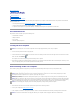
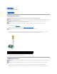
4. Disconnect all telephone or network cables from the computer. 5. Close the display and turn the computer upside down on a flat work surface. NOTICE: To avoid damaging the system board, you must remove the main battery before you service the computer. 6. 1 Disconnect your computer and all attached devices from their electrical outlets. battery 7. 8. 2 battery-bay release latch Remove the main battery: a. Slide the battery-bay release latch on the bottom of the computer. b.
Back to Contents Page Flashing the BIOS Dell™ XPS™ M1330 Service Manual Flashing the BIOS From a CD Flashing the BIOS From the Hard Drive If a BIOS-update program CD is provided with the new system board, flash the BIOS from the CD. If you do not have a BIOS-update program CD, flash the BIOS from the hard drive. Flashing the BIOS From a CD 1. Ensure that the AC adapter is plugged in and that the main battery is installed properly.
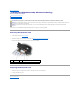
Back to Contents Page Internal Card With Bluetooth® Wireless Technology Dell™ XPS™ M1330 Service Manual Removing the Bluetooth Card Replacing the Bluetooth Card CAUTION: Before you begin any of the procedures in this section, follow the safety instructions in the Product Information Guide. NOTICE: To avoid electrostatic discharge, ground yourself by using a wrist grounding strap or by periodically touching an unpainted metal surface (such as a connector on the back of the computer).
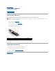
Back to Contents Page LCD Camera (optional) Dell™ XPS™ M1330 Service Manual Removing the LCD Camera Replacing the LCD Camera Removing the LCD Camera CAUTION: Before working inside your computer, follow the safety instructions in the Product Information Guide. NOTICE: To avoid electrostatic discharge, ground yourself by using a wrist grounding strap or by periodically touching an unpainted metal surface (such as a connector on the back of the computer). 1. Follow the instructions in Before You Begin. 2.
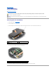
Back to Contents Page Coin-Cell Battery Dell™ XPS™ M1330 Service Manual Removing the Coin-Cell Battery CAUTION: Before you begin any of the procedures in this section, follow the safety instructions in the Product Information Guide. NOTICE: To avoid electrostatic discharge, ground yourself by using a wrist grounding strap or by periodically touching an unpainted metal surface (such as a connector on the back of the computer).
Back to Contents Page
Back to Contents Page Processor Dell™ XPS™ M1330 Service Manual Removing the Processor Installing the Processor Removing the Processor CAUTION: Before working inside your computer, follow the safety instructions in the Product Information Guide. NOTICE: To avoid electrostatic discharge, ground yourself by using a wrist grounding strap or by periodically touching an unpainted metal surface (such as a connector on the back of the computer).
others, the processor is not seated correctly. NOTICE: To prevent intermittent contact between the ZIF-socket cam screw and the processor when removing or replacing the processor, press to apply slight pressure to the center of the processor while turning the cam screw. 2. Tighten the ZIF socket by turning the cam screw clockwise to secure the processor to the system board. 3.
Back to Contents Page Processor Thermal-Cooling Assembly Dell™ XPS™ M1330 Service Manual Removing the Processor Thermal-Cooling Assembly Replacing the Processor Thermal-Cooling Assembly Removing the Processor Thermal-Cooling Assembly CAUTION: Before working inside your computer, follow the safety instructions in the Product Information Guide.
5. Lift the thermal-cooling assembly out of the computer. Replacing the Processor Thermal-Cooling Assembly CAUTION: Before working inside your computer, follow the safety instructions in the Product Information Guide. NOTICE: To prevent static damage to components inside your computer, discharge static electricity from your body before you touch any of your computer's electronic components. You can do so by touching an unpainted metal surface.
Back to Contents Page Display Assembly Dell™ XPS™ M1330 Service Manual Removing the Display Assembly Replacing the Display Assembly Removing the Display Bezel Replacing the Display Bezel Removing the Display Panel Replacing the Display Panel Removing the Display Panel Cable Removing the Display Hinges CAUTION: Before you begin any of the procedures in this section, follow the safety instructions in the Product Information Guide.
8. Make note of the cable routing and carefully dislodge the Mini-Card antenna cables from their routing guides and pull the cables with their connectors through the system board so that they are clear of the computer base. 9. Pull on the display cable pull-tab to disconnect the display cable from the display connector on the system board. 10. If applicable, remove the camera cable connector from the system board. 1 M2.
5. Replace the keyboard (see Keyboard). 6. Turn the computer over and replace the two M2.5 x 5-mm screws labeled "D" on the computer base. 7. Make note of the cable routing and carefully insert the Mini-Card antenna cables through their routing guides. 8. Reconnect the mini card cables to the Mini Cards if applicable (see Wireless Mini Cards). 9. Replace the hinge covers and center control cover (see Hinge Covers and Center Control Cover).
1 display panel 2 screws (4) 3 camera cable connector (optional) 4 display panel-cable connector 5. Remove the camera cable connector. 6. Remove the display panel. 7. Remove the six screws (three on each side) that secure the display panel brackets to the display panel. 1 display panel bracket (1 left, 1 right) 2 screws (6 total; 3 each side) Replacing the Display Panel 1. Replace the six screws that attach the display panel brackets to each side of the display panel. 2.
NOTICE: To avoid damage to the computer when replacing the bottom flex cable, gently support the bottom of the inverter board with one finger as you reseat the bottom flex-cable connector. Do not bend the inverter board. 5. Gently pull the pull-tab on the bottom flex-cable connector to release the cable from the inverter board. 6. Squeeze the flex-cable release levers at either side of the top flex-cable connector, releasing the connector.
Back to Contents Page Hard Drive Dell™ XPS™ M1330 Service Manual Removing the Hard Drive CAUTION: If you remove the hard drive from the computer when the drive is hot, do not touch the metal housing of the hard drive. CAUTION: Before you begin any of the procedures in this section, follow the safety instructions in the Product Information Guide. NOTICE: To prevent data loss, turn off your computer (see Turning Off Your Computer) before removing the hard drive.
Returning a Hard Drive to Dell Return your old hard drive to Dell in its original, or comparable, foam packaging. Otherwise, the hard drive may be damaged in transit.
Back to Contents Page Hinge Covers and Center Control Cover Dell™ XPS™ M1330 Service Manual Removing the Hinge Covers and Center Control Cover Replacing the Hinge Covers and Center Control Cover CAUTION: Before you begin any of the procedures in this section, follow the safety instructions in the Product Information Guide.
1 center control cover 6. Remove the keyboard (see Keyboard). 7. Using your fingernail, pull the cable release tabs forward and remove the center control cover cable. 1 cable release tabs (2) 2 center control cover cable Replacing the Hinge Covers and Center Control Cover 1. Reconnect the cable that attaches the center control cover to the system board, and snap the center control cover in place. 2. Replace the keyboard (see Replacing the Keyboard). 3. Replace the hinge covers. 4.
Back to Contents Page Keyboard Dell™ XPS™ M1330 Service Manual Removing the Keyboard Replacing the Keyboard For more information about the keyboard, see "Using the Keyboard and Touchpad" in your Owner's Manual. CAUTION: Before you begin any of the procedures in this section, follow the safety instructions in the Product Information Guide.
3. Replace the two M2 x 2-mm screws along the top of the keyboard.
Back to Contents Page Memory Dell™ XPS™ M1330 Service Manual Removing the DIMM 1 Memory Module Replacing the DIMM 1 Memory Module Removing the DIMM 2 Memory Module Replacing the DIMM 2 Memory Module CAUTION: Before you begin any of the procedures in this section, follow the safety instructions in the Product Information Guide. You can increase your computer memory by installing memory modules on the system board.
1 upper memory module connector 3 memory module (DIMM 1) 2 securing clips (2) Replacing the DIMM 1 Memory Module NOTICE: To avoid electrostatic discharge, ground yourself by using a wrist grounding strap or by periodically touching an unpainted metal surface (such as a connector on the back of the computer). 1. Align the notch in the module edge connector with the tab in the connector slot. 2.
1 M2.5 x 5-mm screw 2 captive screws (3) NOTICE: To prevent damage to the memory module connector, do not use tools to spread the memory module securing clips. NOTICE: To avoid electrostatic discharge, ground yourself by using a wrist grounding strap or by periodically touching an unpainted metal surface (such as a connector on the back of the computer). 3. Use your fingertips to carefully spread apart the securing clips on each end of the memory module connector until the module pops up. 4.
1 tab 2 notch NOTICE: If the cover is difficult to close, remove the module and reinstall it. Forcing the cover to close may damage your computer. 3. Replace the module cover. 4. Insert the battery into the battery bay, or connect the AC adapter to your computer and an electrical outlet. 5. Turn on the computer. As the computer boots, it detects the additional memory and automatically updates the system configuration information.
Back to Contents Page Communication Cards Dell™ XPS™ M1330 Service Manual Subscriber Identity Module Wireless Mini Cards Flash Cache Module Subscriber Identity Module Subscriber Identity Modules (SIM) identify users uniquely through an International Mobile Subscriber Identity. CAUTION: Before you begin any of the procedures in this section, follow the safety instructions in the Product Information Guide. NOTE: Only Cingular and Vodafone need a SIM. Verizon, Sprint, and Telus do not use SIMs. 1.
4. Disconnect the antenna cables from the WLAN card. 1 WLAN card 2 M2 x 3-mm securing screw 3 antenna cable connectors (2) 5. Release the WLAN card by removing the securing screw. 6. Lift the WLAN card out of its system board connector. Replacing a WLAN Card NOTICE: The connectors are keyed to ensure correct insertion. If you feel resistance, check the connectors on the card and on the system board, and realign the card. NOTICE: To avoid damage to the WLAN card, never place cables under the card.
3. Replace the M2 x 3-mm securing screw. 4. Connect the appropriate antenna cables to the WLAN card you are installing: If the WLAN card has two triangles on the label (white and black), connect the white antenna cable to the connector labeled "main" (white triangle), and connect the black antenna cable to the connector labeled "aux" (black triangle).
Replacing a WWAN Card NOTICE: The connectors are keyed to ensure correct insertion. If you feel resistance, check the connectors on the card and on the system board, and realign the card. NOTICE: To avoid damage to the WWAN card, never place cables under the card. 1. Insert the WWAN card connector at a 45-degree angle into the system board connector labeled "WWAN." 2. Press the other end of the WWAN card down into the slot on the system board until the card clicks into place. 3.
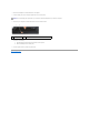
3. Ground yourself by touching one of the metal connectors on the back of the computer. NOTE: If you leave the area, ground yourself again when you return to the computer. 4. Remove the M2 x 3-mm securing screw. 5. Remove the FCM card. 1 FCM card 2 M2 x 3-mm securing screw Replacing the FCM Card NOTICE: Install the FCM card in the WWAN or WPAN slot. Do not install an FCM cardin the WLAN card slot. Doing so may cause damage to your computer. 1.
Back to Contents Page Optical Drive Dell™ XPS™ M1330 Service Manual CAUTION: Before performing the following procedures, follow the safety instructions in the Product Information Guide. NOTICE: To avoid electrostatic discharge, ground yourself by using a wrist grounding strap or by periodically touching a connector on the back panel of the computer. 1. Follow the procedures in Before You Begin. 2. Remove the hinge covers and center control cover (see Hinge Covers and Center Control Cover). 3.
Back to Contents Page Palm Rest Dell™ XPS™ M1330 Service Manual Removing the Palm Rest Replacing the Palm Rest Removing the Palm Rest CAUTION: Before you begin any of the procedures in this section, follow the safety instructions in the Product Information Guide. NOTICE: To avoid electrostatic discharge, ground yourself by using a wrist grounding strap or by periodically touching an unpainted metal surface (such as the back panel) on the computer. 1. Follow the instructions in Before You Begin. 2.
1 palm rest 2 touch pad connector NOTICE: Carefully separate the palm rest from the computer base to avoid damage to the palm rest. 9. Starting at the back center of the palm rest, use your fingers to separate the palm rest from the computer base by lifting the inside of the palm rest while pushing in on the outside. Replacing the Palm Rest 1. Align the palm rest with the computer base and gently snap it into place. 2. Connect the touch pad connector to the system board. 3.
Back to Contents Page ExpressCard Reader Dell™ XPS™ M1330 Service Manual CAUTION: Before performing the following procedures, follow the safety instructions in the Product Information Guide. NOTICE: To avoid electrostatic discharge, ground yourself by using a wrist grounding strap or by periodically touching a connector on the back panel of the computer. 1. Follow the procedures in Before You Begin. 2. Remove any installed ExpressCards from the ExpressCard slot. 3.
Back to Contents Page Pin Assignments for I/O Connectors Dell™ XPS™ M1330 Service Manual USB Connector Video Connector HDMI Connector USB Connector Pin Signal 1 USB5V+ 2 USBP– 3 USBP+ 4 GND Video Connector NOTE: The color of the video connector may vary in color between blue and black.
Pin Signal Pin Signal 1 TMDS Data 2+ 11 2 TMDS Data 2 Shield 12 TMDS Clock- 3 TMDS Data 2- 13 CEC 4 TMDS Data 1+ 14 No Connect 5 TMDS Data 1 Shield 15 DDC Clock 6 TMDS Data 1- 16 DDC Data 7 TMDS Data 0+ 17 Ground 8 TMDS Data 0 Shield 18 +5V Power 9 TMDS Data 0- 19 Hot Plug Detect 10 TMDS Clock+ 20 SHELL Back to Contents Page TMDS Clock Shield
Back to Contents Page Wireless Sniffer Board Dell™ XPS™ M1330 Service Manual CAUTION: Before you begin any of the procedures in this section, follow the safety instructions in the Product Information Guide. NOTICE: To avoid electrostatic discharge, ground yourself by using a wrist grounding strap or by periodically touching an unpainted metal surface (such as the back panel) on the computer. NOTICE: Handle components and cards by their edges, and avoid touching pins and contacts. 1.
Back to Contents Page Speaker Dell™ XPS™ M1330 Service Manual CAUTION: Before you begin any of the procedures in this section, follow the safety instructions in the Product Information Guide. NOTICE: To avoid electrostatic discharge, ground yourself by using a wrist grounding strap or by periodically touching an unpainted metal surface (such as the back panel) on the computer. 1. Follow the instructions in Before You Begin. 2. Remove any installed ExpressCards from the ExpressCard slot. 3.
Back to Contents Page System Board Dell™ XPS™ M1330 Service Manual Removing the System Board Replacing the System Board Removing the System Board CAUTION: Before you begin any of the procedures in this section, follow the safety instructions in the Product Information Guide. NOTICE: To avoid electrostatic discharge, ground yourself by using a wrist grounding strap or by periodically touching an unpainted metal surface (such as the back panel) on the computer.
17. Lift the system board at an angle toward the side of the computer and out of the computer base. 1 speaker cable connector 2 power button cable connector 3 power button cable release tabs (2) Replacing the System Board 1. Follow all of the steps in Removing the System Board in reverse order. NOTICE: Before turning on the computer, replace all screws and ensure that no stray screws remain inside the computer. Failure to do so may result in damage to the computer. 2. Turn on the computer.
Back to Contents Page Dell™ XPS™ M1330 Service Manual NOTE: A NOTE indicates important information that helps you make better use of your computer. NOTICE: A NOTICE indicates either potential damage to hardware or loss of data and tells you how to avoid the problem. CAUTION: A CAUTION indicates a potential for property damage, personal injury, or death. Information in this document is subject to change without notice. © 2007 Dell Inc. All rights reserved.