Dell Precision Mobile Workstation M6700 Owner's Manual Regulatory Model: P22F Regulatory Type: P22F001
Notes, Cautions, and Warnings NOTE: A NOTE indicates important information that helps you make better use of your computer. CAUTION: A CAUTION indicates either potential damage to hardware or loss of data and tells you how to avoid the problem. WARNING: A WARNING indicates a potential for property damage, personal injury, or death. © 2013 Dell Inc. All Rights Reserved.
Contents 1 Working on Your Computer....................................................................................................... 7 Before Working Inside Your Computer.....................................................................................................................7 Recommended Tools................................................................................................................................................ 8 Turning Off Your Computer............................
Installing the Primary Memory............................................................................................................................... 27 Removing the Secondary Memory......................................................................................................................... 28 Installing the Secondary Memory.......................................................................................................................... 28 Removing the Bluetooth Module............
Updating the BIOS ................................................................................................................................................. 69 System and Setup Password..................................................................................................................................69 Assigning a System Password and Setup Password......................................................................................
Working on Your Computer 1 Before Working Inside Your Computer Use the following safety guidelines to help protect your computer from potential damage and to help to ensure your personal safety. Unless otherwise noted, each procedure included in this document assumes that the following conditions exist: • You have read the safety information that shipped with your computer. • A component can be replaced or--if purchased separately--installed by performing the removal procedure in reverse order.
NOTE: To avoid damaging the system board, you must remove the main battery before you service the computer. 7. Remove the main battery. 8. Turn the computer top-side up. 9. Open the display. 10. Press the power button to ground the system board. CAUTION: To guard against electrical shock, always unplug your computer from the electrical outlet before opening the display.
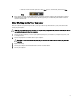
2. Click the arrow in the lower-right corner of the Start menu as shown below, and then click Shut 2. Down.. Ensure that the computer and all attached devices are turned off. If your computer and attached devices did not automatically turn off when you shut down your operating system, press and hold the power button for about 4 seconds to turn them off.
Removing and Installing Components 2 This section provides detailed information on how to remove or install the components from your computer. Removing the Secure Digital (SD) Card 1. Follow the procedures in Before Working Inside Your Computer. 2. Press in on the SD card to release it from the computer. Slide the SD card out of the computer. Installing the SD Card 1. Push in the SD card into its slot until it clicks into place. 2. Follow the procedures in After Working Inside Your Computer.
3. Flip and remove the battery from the computer. Installing the Battery 1. Slide the battery into its slot until it clicks into place. 2. Follow the procedures in After Working Inside Your Computer. Removing the Subscriber Identity Module (SIM) Card 1. Follow the procedures in Before Working Inside Your Computer. 2. Remove the battery.
3. Slide the SIM card out from the slot . Installing the Subscriber Identity Module (SIM) Card 1. Push in the SIM card into its slot. 2. Install the battery. 3. Follow the procedures in After Working Inside Your Computer. Removing the Base Cover 1. Follow the procedures in Before Working Inside Your Computer. 2. Remove the battery. 3. Remove the screws that secure the base cover to the computer. Press the rubber tabs towards the rear of the computer to disengage the base cover.
4. Flip and remove the base cover from the computer. Installing the Base Cover 1. Slide in and place the base cover to align with the screw holes correctly on the computer. 2. Tighten the screws to secure the base cover to the computer. 3. Install the battery. 4. Follow the procedures in After Working Inside Your Computer.
Removing the Wireless Local Area Network (WLAN) Card 1. Follow the procedures in Before Working Inside Your Computer. 2. Remove the: a) battery b) base cover 3. Disconnect and un-route the antenna cables connected to the WLAN card. Remove the screw that secures the WLAN card to the computer. Remove the WLAN card from the computer. Installing the Wireless Local Area Network (WLAN) Card 1. Insert the WLAN card in its slot in the computer. 2. Tighten the screw to secure the WLAN card to the computer.
Installing the Wireless Wide Area Network (WWAN) Card (Optional) 1. Slide the WWAN card in the WWAN card slot. 2. Tighten the screw to secure the WWAN card to the computer. 3. Route the cables through the routing channels and connect them to the WWAN card. 4. Install the: a) base cover b) battery 5. Follow the procedures in After Working Inside Your Computer. Removing the Optical Drive 1. Follow the procedures in Before Working Inside Your Computer. 2. Remove the: a) battery b) base cover 3.
5. Remove the screws that secure the drive-latch bracket to the optical drive and remove the bracket. Installing the Optical Drive 1. Tighten the screws to secure the drive-latch bracket to the optical drive. 2. Slide the optical drive into its slot and tighten the screw to secure the optical drive to the computer. 3. Install the: a) battery b) base cover 4. Follow the procedures in After Working Inside Your Computer.
Removing the Primary Hard Drive 1. Follow the procedures in Before Working Inside Your Computer. 2. Remove the: a) battery b) base cover 3. Remove the screws that secure the primary hard drive to the computer. Slide the primary hard -drive latch to the unlock position and pull out the hard drive from the computer. 4. Flex the hard-drive bracket outward and pull out the hard drive from the bracket. NOTE: A rubber filler is installed to the hard-drive bracket for 7 mm hard drives.
Installing the Primary Hard Drive 1. Engage the primary hard -drive bracket to the primary hard drive. 2. Insert the primary hard drive into its slot in the computer till it clicks in place. 3. Tighten the screws to secure the primary hard drive to the computer. 4. Install the: a) base cover b) battery 5. Follow the procedures in After Working Inside Your Computer. Removing the Secondary Hard Drive 1. Follow the procedures in Before Working Inside Your Computer. 2.
Installing the Secondary Hard Drive 1. Engage the secondary hard drive bracket to the secondary hard drive. 2. Tighten the screw that secure the secondary hard drive bracket. 3. Install the secondary hard drive into the computer. 4. Tighten the screw that secure the secondary hard drive in the computer. 5. Install the: a) base cover b) battery 6. Follow the procedures in After Working Inside Your Computer. Removing the Coin-Cell Battery 1.
Installing the Coin-Cell Battery 1. Replace the coin-cell battery in its slot in the computer. 2. Connect the coin-cell battery cable. 3. Install the: a) base cover b) battery 4. Follow the procedures in After Working Inside Your Computer. Removing the Processor Fan 1. Follow the procedures in Before Working Inside Your Computer. 2. Remove the: a) battery b) base cover 3. Remove the screws that secure the processor fan to the computer. Remove the processor fan from the computer. 4.
Installing the Processor Fan 1. Connect the processor-fan cable. 2. Insert the processor fan into its slot in the computer. 3. Tighten the screws that secure the processor fan to the computer. 4. Install the: a) base cover b) battery 5. Follow the procedures in After Working Inside Your Computer. Removing the Video-Card Fan 1. Follow the procedures in Before Working Inside Your Computer. 2. Remove the: a) battery b) base cover 3.
4. Pry up the bottom edge of the keyboard trim from the top-inner edge.
Installing the Keyboard Trim 1. Toe-in the keyboard trim from the front and align it to its original position on the computer. Ensure that the hard-tab on the left corner snaps into place. 2. Press along the sides of the keyboard trim until it snaps in place. 3. Install the battery. 4. Follow the procedures in After Working Inside Your Computer. Removing the Keyboard 1. Follow the procedures in Before Working Inside Your Computer. 2. Remove the: a) battery b) keyboard trim 3.
4. Starting from the bottom of the keyboard, separate the keyboard from the computer and flip the keyboard over. 5. Disconnect the keyboard-data cable from the system board and remove the keyboard.
Installing the Keyboard 1. Connect the keyboard-data cable to the system board. NOTE: Ensure that you fold the keyboard-data cable in perfect alignment. 2. Press the keyboard in its compartment. 3. Tighten the screws to secure the keyboard to the computer. 4.
5. Install the: a) keyboard trim b) battery 6. Follow the procedures in After Working Inside Your Computer. Removing the Primary Memory 1. Follow the procedures in Before Working Inside Your Computer. 2. Remove the: a) battery b) base cover 3. Pry the retention clips away from the primary memory until it pops up. Lift the primary memory and remove it from the computer. Installing the Primary Memory 1. Insert the primary memory into the memory socket. 2.
a) base cover b) battery 4. Follow the procedures in After Working Inside Your Computer. Removing the Secondary Memory 1. Follow the procedures in Before Working Inside Your Computer. 2. Remove the: a) battery b) keyboard trim c) keyboard 3. Remove the screw that secures the memory shield to the computer and remove the memory shield. 4. Pry the retention clips away from the memory module until it pops up. Lift up the memory module and remove it from the computer. Installing the Secondary Memory 1.
Removing the Bluetooth Module 1. Follow the procedures in Before Working Inside Your Computer. 2. Remove the: a) battery b) base cover 3. Disconnect and un-route the bluetooth cable. Slide the bluetooth door upward to release it. 4. Remove the bluetooth module from the computer. Remove the screw that secures the bluetooth module in place. 5. Remove the bluetooth module. Disconnect and remove the bluetooth cable from the module.
Installing the Bluetooth Module 1. Connect the bluetooth cable to the bluetooth module. 2. Tighten the screw to secure the bluetooth module in place. 3. Insert the bluetooth module in its slot and press down the bluetooth door. 4. Route and connect the bluetooth cable. 5. Install the: a) base cover b) battery 6. Follow the procedures in After Working Inside Your Computer. Removing the Display Bezel 1. Follow the procedures in After Working Inside Your Computer. 2. Remove the battery. 3.
Installing the Display Bezel 1. Slide in the display bezel from the bottom and press on the display bezel. 2. Work around the entire bezel until it snaps onto the display assembly. 3. Install the battery. 4. Follow the procedures in After Working Inside Your Computer.
Removing the Camera 1. Follow the procedures in Before Working Inside Your Computer. 2. Remove the: a) battery b) display bezel 3. Disconnect the camera cable. Remove the screw that secures the camera module to the computer. Remove the camera module from the computer. Installing the Camera 1. Place the camera module in its slot on the computer. 2. Tighten the screw to secure the camera module to the computer. 3. Connect the camera cable. 4. Install the: a) display bezel b) battery 5.
4. Peel back the adhesive tape that secures the LVDS cable to the display panel. 5. Disconnect the LVDS cable.
6. 7. 34 Remove the screws that secure the display brackets to the display panel. Remove the display brackets.
Installing the Display Panel 1. Align the display brackets to the display panel. 2. Tighten the screws to secure the display brackets to the display panel. 3. Connect the LVDS cable and affix the adhesive tape. 4. Align the display panel in its original position on the computer. 5. Tighten the screws to secure the display panel to the display assembly. 6. Install the: a) display bezel b) battery 7. Follow the procedures in After Working Inside Your Computer. Removing the Palmrest 1.
5. Remove the screws at the bottom of the computer. 6. Peel the adhesive tape that secures the media board cable and speaker cable to the palmrest.
7. Disconnect the media board cable and the speaker cable from the system board. 8. Peel the adhesive tape that secures the touchpad cable to the palmrest. 9. Disconnect the touchpad cable from the system board.
10. Disconnect the power button cable from the system board. 11. Disconnect the bluetooth module cable from the system board. 12. Remove the screws that secure the palmrest to the computer.
13. Lift the left edge of the palmrest. Release the tabs on the right edge of the palmrest and remove the palmrest from the computer.
Installing the Palmrest 1. Align the palmrest to its original position on the computer and press on the positions indicated until it snaps in place. 2. Tighten the screw that secures the palmrest to the computer. 3. Connect the following cables: a) b) c) d) e) bluetooth module power button touchpad media board speaker 4. Affix the adhesive tape that secures the media card cable, speaker cable and touchpad cable to the palmrest. 5. Tighten the screws at the bottom of the computer. 6.
Removing the ExpressCard Module 1. Follow the procedures in Before Working Inside Your Computer. 2. Remove the: a) b) c) d) e) f) g) h) 3. ExpressCard battery base cover keyboard trim keyboard optical drive primary and secondary hard drive palm rest Disconnect the : a) ExpressCard cable from the system board b) the USH board cable from the USH board (M4700 only) 4. Remove the screws that secure the ExpressCard module to the computer and remove the ExpressCard module.
Installing the ExpressCard Module 1. Insert the ExpressCard module into its compartment. 2. Tighten the screws to secure the ExpressCard module to the computer 3. Connect the: a) ExpressCard cable to the system board b) the USH board cable to the USH board (for M4700 only) 4. Install the: a) b) c) d) e) f) g) h) 5. palm rest primary and secondary hard drive optical drive keyboard keyboard trim base cover battery ExpressCard Follow the procedures in After Working Inside Your Computer.
Installing the Heat Sink 1. Replace the heat sink in its slot. 2. Tighten the captive screws to secure the heat sink to the computer. 3. Connect the camera cable to the system board. 4. Install the: a) b) c) d) e) f) g) h) 5. processor fan palm rest primary and secondary hard drive optical drive keyboard keyboard trim base cover battery Follow the procedures in After Working Inside Your Computer. Removing the Processor 1. Follow the procedures in Before Working Inside Your Computer. 2.
Installing the Processor 1. Align the notches on the processor and the socket, and insert the processor into the socket. 2. Rotate the processor cam lock in a clockwise direction. 3. Install the: a) b) c) d) e) f) g) h) i) 4. heat sink processor fan palm rest primary and secondary hard drive optical drive keyboard keyboard trim base cover battery Follow the procedures in After Working Inside Your Computer. Removing the Video-Card Heatsink 1.
4. Remove the video-card heatsink from the computer. Installing the Video-Card Heatsink 1. Place the heatsink on its original position in the computer. 2. Tighten the captive screws to secure the heatsink. 3.
i) 4. battery Follow the procedures in After Working Inside Your Computer. Removing the Video Card 1. Follow the procedures in Before Working Inside Your Computer. 2. Remove the: a) b) c) d) e) f) g) h) i) j) 3. battery base cover keyboard trim keyboard optical drive primary and secondary hard drive palm rest video-card fan video-card heat sink heatsink Remove the screws that secure the video card to the computer. Remove the video card from the computer. Installing the Video Card 1.
Removing the Input/Output (I/O) Board 1. Follow the procedures in Before Working Inside Your Computer. 2. Remove the: a) b) c) d) e) f) g) h) SD card battery base cover keyboard trim keyboard optical drive primary and secondary hard drive palmrest 3. Disconnect the ExpressCard module connector from the I/O board. 4. Remove the screw that secures the I/O board to the computer. Lift the right edge of the I/O board upwards to disengage the connector and remove it from computer.
Installing the I/O Board 1. Connect the I/O board connector and slide the I/O board into its slot in the computer. 2. Tighten the screw to secure the I/O board to the computer. 3. Connect the ExpressCard module connector to the I/O board. 4. Install the: a) b) c) d) e) f) g) h) 5. palmrest primary and secondary hard drive optical drive keyboard keyboard trim base cover battery SD card Follow the procedures in After Working Inside Your Computer. Removing the Display Assembly 1.
g) palmrest 3. Disconnect the antenna cables from the wireless cards, and push them down the routing hole. 4. Flip the computer and pull up the antenna cables through the routing hole. 5. Flip the computer and remove the screws from the bottom and back of the computer.
6. Remove the screws that secure the low-voltage differential signalling (LVDS) cable bracket. Remove the LVDS cable bracket and disconnect the LVDS cable and camera cable from the system board. NOTE: LVDS cable is available in M4700 without the bracket. LVDS cable bracket is available only in M6700. 7. 50 Remove the screws that secure the display assembly to the computer. Remove the display assembly from the computer.
Installing the Display Assembly 1. Tighten the screws to secure the display assembly in place. 2. Connect the camera and LVDS cables to the correct connectors on the system board. 3. Place the LVDS cable bracket on the computer and tighten the screws to secure it to the computer. NOTE: LVDS cable is available in M4700 without the bracket. LVDS cable bracket is available only in M6700. 4. Route the cables through the routing channels. 5.
a) b) c) d) e) f) g) h) i) battery base cover keyboard trim keyboard optical drive primary and secondary hard drive palmrest display assembly display bezel 3. Remove the screw that secures the left display hinge to the computer. 4. Remove the left display hinge and the left hinge tower from the computer. 5. Repeat steps 3 and 4 to remove the right display hinge and right hinge tower. Installing the Display Hinges and Hinge Towers 1.
Installing the Hinge Cover 1. Place the hinge cover in its position on the computer. 2. Tighten the screws to secure the hinge cover to the computer. 3. Install the: a) b) c) d) e) f) g) h) 4. display assembly palmrest primary and secondary hard drive optical drive keyboard keyboard trim base cover battery Follow the procedures in After Working Inside Your Computer. Removing the System Board 1. Follow the procedures in Before Working Inside Your Computer. 2.
p) video card q) I/O board r) display assembly 3. Disconnect the processor-fan cable and the coin-cell battery cable from the system board. 4. Remove the screws that secure the low-voltage differential signaling (LVDS) cable bracket to the computer and remove it from the computer. 5. Disconnect the LVDS , camera and power connector cables from the system board.
6. Disconnect the switch board cable from the system board. 7. Remove any mini-cards (if available). 8. Remove the screws that secure the system board to the computer and lift the bottom edge of the system board at a 20–degree angle.
9. Remove the system board from the computer. Installing the System Board 1. Align the system board into its original position on the computer. 2. Tighten the screws to secure the system board to the computer. 3.
a) b) c) d) e) f) switch board power connector LVDS camera coin-cell battery processor fan 4. Install all the mini-cards (if available). 5. Place the LVDS cable bracket in its original position on the computer and tighten the screws to secure it to the computer. 6. Install the: a) b) c) d) e) f) g) h) i) j) k) l) m) n) o) p) q) 7. I/O board video card video-card heat sink.
Installing the Power Connector Port 1. Insert the power-connector port in its slot and connect the power-connector cable to the system board. 2. Install the: a) b) c) d) e) f) g) h) i) 3. display assembly I/O board palmrest primary and secondary hard drive optical drive keyboard keyboard trim base cover battery Follow the procedures in After Working Inside Your Computer. Removing the Switch Board 1. Follow the procedures in Before Working Inside Your Computer. 2.
Installing the Switch Board 1. Align the switch board to its original position on the computer. 2. Tighten the screws to secure the switch board to the computer. 3. Connect the switch-board cable to the system board and secure it through the routing channel. 4. Install the: a) b) c) d) e) f) g) 5. palmrest primary and secondary hard drive optical drive keyboard keyboard trim base cover battery Follow the procedures in After Working Inside Your Computer.
System Setup 3 System Setup enables you to manage your computer hardware and specify BIOS‐level options.
Keys Navigation Allows you to select a value in the selected field (if applicable) or follow the link in the field. Spacebar Expands or collapses a drop‐down list, if applicable. Moves to the next focus area. NOTE: For the standard graphics browser only. Moves to the previous page till you view the main screen. Pressing in the main screen displays a message that prompts you to save any unsaved changes and restarts the system. Displays the System Setup help file.
Option Description • • • Parallel Port Allows you to define and set how the parallel port on the docking station operates. You can set the parallel port to: • • • • Serial Port Disabled Enabled Enabled w/PXE (Default Setting) Disabled AT PS2 ECP Identifies and defines the serial port settings. You can set the serial port to: • • • • • Disabled COM1 (Default Setting) COM2 COM3 COM4 NOTE: The operating system may allocate resources even if the setting is disabled.
Option Description • USB Configuration Enable SMART Reporting - This option is disabled by default. Allows you to define the USB configuration. The options are: • • Enable Boot Support Enable External USB Port Default Setting: both the options are enabled. USB PowerShare Allows you to configure the behavior of the USB PowerShare feature. The option is disabled by default. • Miscellaneous Devices Enable USB PowerShare Allows you enable or disable the various on board devices.
Option Description NOTE: Successful password changes take effect immediately. Default Setting: Not set System Password Allows you to set, change or delete the system password. NOTE: Successful password changes take effect immediately. Default Setting: Not set Internal HDD-0 Password Allows you to set, change or delete the administrator password. Default Setting: Not set Strong Password Allows you to enforce the option to always set strong passwords.
Table 6. Performance Option Description Multi Core Support This field specifies whether the process will have one or all cores enabled. The performance of some applications will improve with the additional cores. This option is enabled by default. Allows you to enable or disable multi-core support for the processor. The options are: • • • All (Default Setting) 1 2 Intel SpeedStep Allows you to enable or disable the Intel SpeedStep feature.
Option Description Wireless Radio Control Allows you to control the WLAN and WWAN radio. The options are: • • Control WLAN radio Control WWAN radio Default Setting: both the options are disabled. Wake on LAN/WLAN This option allows the computer to power up from the off state when triggered by a special LAN signal. Wake-up from the Standby state is unaffected by this setting and must be enabled in the operating system. This feature only works when the computer is connected to AC power supply.
Option Description • Numlock Enable Specifies if the NumLock function can be enabled when the computer boots. This option is enabled by default. • Fn Key Emulation Enable Fn Key Emulation Specifies whether keyboard related errors are reported when it boots. This option is enabled by default. • POST Hotkeys Enable Numlock Allows you to match the key feature of PS-2 keyboard with the key feature in an internal keyboard. The option is enabled by default.
Option Description All options are enabled by default. Table 11. Maintenance Option Description Service Tag Displays the service tag of your computer. Asset Tag Allows you to create a system asset tag if an asset tag is not already set. This option is not set by default. Table 12. System Logs Option Description BIOS events Displays the system event log and allows you to clear the log. Thermal Events Displays the thermal event logs and allows you clear the thermal event log.
Password Type Description System password Password that you must enter to log on to your system. Setup password Password that you must enter to access and make changes to the BIOS settings of your computer. CAUTION: The password features provide a basic level of security for the data on your computer. CAUTION: Anyone can access the data stored on your computer if it is not locked and left unattended. NOTE: Your computer is shipped with the system and setup password feature disabled.
To enter the System Setup, press immediately after a power-on or reboot. 1. In the System BIOS or System Setup screen, select System Security and press . The System Security screen is displayed. 2. In the System Security screen, verify that Password Status is Unlocked. 3. Select System Password, alter or delete the existing system password and press or . 4. Select Setup Password, alter or delete the existing setup password and press or .
Diagnostics 4 If you experience a problem with your computer, run the ePSA diagnostics before contacting Dell for technical assistance. The purpose of running diagnostics is to test your computer's hardware without requiring additional equipment or risking data loss. If you are unable to fix the problem yourself, service and support personnel can use the diagnostics results to help you solve the problem.
Troubleshooting Your Computer 5 You can troubleshoot your computer using indicators like Diagnostic Lights, Beep Codes, and Error Messages during the operation of the computer. Device Status Lights Table 13. Device Status Lights Turns on when you turn on the computer and blinks when the computer is in a power management mode. Turns on when the computer reads or writes data. Turns on steadily or blinks to indicate battery charge status. Turns on when wireless networking is enabled.
Battery Status Lights If the computer is connected to an electrical outlet, the battery light operates as follows: Alternately blinking amber light and white light An unauthenticated or unsupported non-Dell AC adapter is attached to your laptop. Alternately blinking amber light with steady white light Temporary battery failure with AC adapter present. Constantly blinking amber light Fatal battery failure with AC adapter present. Light off Battery in full charge mode with AC adapter present.
6 Specifications Technical Specification NOTE: Offerings may vary by region. For more information regarding the configuration of your computer, click Start (Start icon) → Help and Support, and then select the option to view information about your computer. Table 15.
Feature Maximum memory Specification • • Intel Core i5 and i7 Dual Core processors — 16 GB Intel Core i7 Quad Core and i7 Quad Extreme processors — 32 GB Table 18.
Table 22. Ports and Connectors Feature Specification Audio two connectors for line-out and line-in/microphone Network Adapter one RJ45 connector USB 2.0 two USB 3.0 two eSATA\USB 2.
Feature M4700 Refresh rate 60 Hz M6700 Minimum viewing angles: Horizontal +/- 40°, +/-60° (FHD) Vertical +10°/-30°, +/- 50° (FHD) Table 24. Keyboard Feature Number of keys Layout Specification • • • • United States: 86 keys United Kingdom: 87 keys Brazil: 87 keys Japan: 90 keys QWERTY/AZERTY/Kanji Table 25. Touchpad Feature Specification Active Area: X-axis 80.00 mm Y-axis 40.50 mm Table 26.
Feature Specification NOTE: The size of the hard drive is bound to change. For more information, see dell.com. Optical Drive: Interface Configuration • • SATA 1 (1.5 Gb/s) SATA 2 (3.0 Gb/s) support ODD modules and Air Bay with SATA HDD option Table 28. Battery Feature Specification Type lithium ion Dimensions (6-cell / 9-cell / 9-cell long cycle life (LCL)): Depth 82.60 mm (3.25 inches) Height 190.65 mm (7.50 inches) Width 20 mm (0.78 inches) Weight Voltage • • 6-cell - 345 g (0.
Feature Depth M4700 M6700 76 mm (2.99 inches) 100 mm (3.93 inches) Temperature range: Operating 0 °C to 40 °C (32 °F to 104 °F) Non Operating –40 °C to 65 °C (–40 °F to 149 °F) Table 30. Contactless Smart Card Feature Supported Smart Cards and Technologies Specification • • • • • • ISO14443A — 160 kbps, 212 kbps, 424 kbps, and 848 kbps ISO14443B — 160 kbps, 212 kbps, 424 kbps, and 848 kbps ISO15693 HID iClass FIPS201 NXP Desfire Table 31. Physical Dimension Physical M4700 M6700 Height 32.
Feature Specification Altitude: Storage Airborne contaminant level 0 m to 10668 m (0 ft to 35,000 ft) G1 or lower as defined by ANSI/ISA-S71.
Getting Help 7 Contacting Dell NOTE: If you do not have an active Internet connection, you can find contact information on your purchase invoice, packing slip, bill, or Dell product catalog. Dell provides several online and telephone-based support and service options. Availability varies by country and product, and some services may not be available in your area. To contact Dell for sales, technical support, or customer service issues: 1. Visit dell.com/support 2. Select your support category. 3.