
Installation and Service Manual
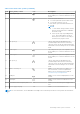
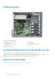
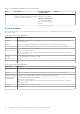
Table Of Contents
- Dell EMC PowerEdge T150 Installation and Service Manual
- Contents
- About this document
- PowerEdge T150 system overview
- Initial system setup and configuration
- Minimum to POST and system management configuration validation
- Installing and removing system components
- Safety instructions
- Before working inside your system
- After working inside your system
- Recommended tools
- System cover
- Frontbezel
- Drives
- Removing a 3.5-inch drive carrier from the drive bay
- Installing a 3.5-inch drive carrier into the drive bay
- Removing a drive from the drive carrier
- Installing a drive into the drive carrier
- Removing a 2.5-inch drive from the 3.5-inch drive adapter
- Installing a 2.5-inch drive into the 3.5-inch drive adapter
- Removing a 3.5-inch drive adapter from a 3.5-inch drive carrier
- Installing a 3.5-inch adapter into a 3.5-inch drive carrier
- Setting the cooling fan speed for 8 TB drives
- Cable routing
- Optional optical drive
- System memory
- Cooling fans
- Internal USB memory key
- Expansion cards
- Optional BOSS S1 card
- Processor and heat sink
- Power supply unit
- System battery
- Intrusion switch
- System board
- Trusted Platform Module
- Control panel
- Jumpers and connectors
- System diagnostics and indicator codes
- Getting help
- Documentation resources

Table 2. Rear view of the system (continued)
Item Ports, panels, or slots Icon Descriptions
6 USB 2.0 port (4) The USB ports are 4-pin, 2.0-compliant. These
ports enable you to connect USB devices to the
system.
7 System identification button Press the system ID button:
● To locate a particular system within a rack.
● To turn the system ID on or off.
To reset iDRAC, press and hold the button for
16 seconds.
NOTE:
● To reset iDRAC using system ID, ensure
that the system ID button is enabled in
the iDRAC setup.
● If the system stops responding during
POST, press and hold the system ID
button (for more than five seconds) to
enter the BIOS progress mode.
8 NIC ports (2) The NIC ports that are integrated on the
system board provide network connectivity.
These NIC ports can also be shared with iDRAC
when iDRAC network settings are set to shared
mode.
9 USB 3.0 port The USB ports are 9-pin, 3.0-compliant. These
ports enable you to connect USB devices to the
system.
10 USB 2.0 port The USB ports are 4-pin, 2.0-compliant. These
ports enable you to connect USB devices to the
system.
11 NIC ports (1) The NIC ports that are integrated on the
system board provide network connectivity.
These NIC ports can also be shared with iDRAC
when iDRAC network settings is set to shared
mode.
12 iDRAC ethernet port Enables you to remotely access iDRAC. For
more information, see the Integrated Dell
Remote Access Controller User's Guide at
www.dell.com/poweredgemanuals.
13 VGA port Enables you to connect a display device to the
system.
14 Serial port Enables you to connect a serial device to the
system.
15 PSU Built-in Self-Test (BIST) LED N/A Enables you to check the power supply to the
PSU.
16 Power supply unit plug N/A Enables you to install cabled AC PSU.
NOTE: For more information, see the Dell EMC PowerEdge T150 Technical Specifications on the product documentation
page.
PowerEdge T150 system overview 11