
Installation and Service Manual
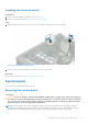
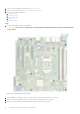
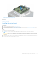
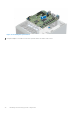
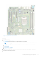
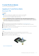
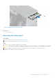
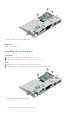
Table Of Contents
- Dell EMC PowerEdge T150 Installation and Service Manual
- Contents
- About this document
- PowerEdge T150 system overview
- Initial system setup and configuration
- Minimum to POST and system management configuration validation
- Installing and removing system components
- Safety instructions
- Before working inside your system
- After working inside your system
- Recommended tools
- System cover
- Frontbezel
- Drives
- Removing a 3.5-inch drive carrier from the drive bay
- Installing a 3.5-inch drive carrier into the drive bay
- Removing a drive from the drive carrier
- Installing a drive into the drive carrier
- Removing a 2.5-inch drive from the 3.5-inch drive adapter
- Installing a 2.5-inch drive into the 3.5-inch drive adapter
- Removing a 3.5-inch drive adapter from a 3.5-inch drive carrier
- Installing a 3.5-inch adapter into a 3.5-inch drive carrier
- Setting the cooling fan speed for 8 TB drives
- Cable routing
- Optional optical drive
- System memory
- Cooling fans
- Internal USB memory key
- Expansion cards
- Optional BOSS S1 card
- Processor and heat sink
- Power supply unit
- System battery
- Intrusion switch
- System board
- Trusted Platform Module
- Control panel
- Jumpers and connectors
- System diagnostics and indicator codes
- Getting help
- Documentation resources

Figure 55. Removing the system board
Next steps
Install the system board.
Installing the system board
Prerequisites
1. Follow the safety guidelines listed in the Safety instructions.
2. Follow the procedure listed in Before working inside your system.
3. If you are replacing the system board, remove all the components that are listed in the removing the system board section.
Steps
1. Unpack the new system board assembly.
NOTE: Do not lift the system board by holding a memory module, the processor, or any other components.
CAUTION: Take care not to damage the system identification button while placing the system board into the
chassis.
2. Holding the blue holder, incline the system board at an angle and align the connectors on the system board with the slots on
the system, and lower the system board into the system.
Installing and removing system components
63