Dell EMC Storage Systems Administrator Guide for PowerStore and Unity XT metro node feature Version 7.
Notes, cautions, and warnings NOTE: A NOTE indicates important information that helps you make better use of your product. CAUTION: A CAUTION indicates either potential damage to hardware or loss of data and tells you how to avoid the problem. WARNING: A WARNING indicates a potential for property damage, personal injury, or death. © 2020 2021 Dell Inc. or its subsidiaries. All rights reserved. Dell, EMC, and other trademarks are trademarks of Dell Inc. or its subsidiaries.
Contents Chapter 1: CLI Workspace and User Accounts................................................................................7 Configure the CLI workspace........................................................................................................................................... 7 Set the threshold for console logging.......................................................................................................................7 Set window width to 100.............................
Chapter 6: Volume expansion....................................................................................................... 31 Overview.............................................................................................................................................................................. 31 Additional documentation...........................................................................................................................................31 Volume expansion method...
subnets context........................................................................................................................................................... 54 /connectivity/back-end/ .........................................................................................................................................55 /connectivity/front-end/ ........................................................................................................................................
Port Monitoring.................................................................................................................................................................. 91 Getting Started.............................................................................................................................................................91 Setting up the script for e-mailing of reports ......................................................................................................
1 CLI Workspace and User Accounts This chapter describes how to use the metro node command line interface (CLI) to configure the CLI workspace and manage user accounts. Topics: • Configure the CLI workspace Configure the CLI workspace The workspace is the appearance and behavior of a CLI session. Use the procedures described in this section to control the output of commands, the level of logging messages sent to the console, and to search the command history of the current CLI session.
4. Use the log filter create command to create a new filter for the console with the required threshold: VPlexcli:> log filter create --threshold --component “logserver” where n is 0-7. NOTE: The threshold value filters all messages with greater or equal severity. To see critical (2) and above (0 and 1), set the threshold at 3. To see error (3) and above (0, 1, and 2) set the threshold at 4. Set window width to 100 Output from many commands is more than 80 columns wide.
2 Meta Volumes This chapter describes the procedures to manage metadata and meta-volumes using the metro node CLI. Topics: • • • • • • About meta-volumes Moving a meta-volume Renaming a meta-volume Deleting a meta-volume Displaying metavolume Verifying consistency of a meta-volume About meta-volumes metro node metadata includes virtual to physical mappings, data about devices, virtual volumes, and system configuration settings.
Availability is critical for metavolumes. The metavolume is essential for system recovery. The best practice is to mirror the metavolume across two or more back-end arrays to eliminate the possibility of data loss. Choose the arrays that mirror the metavolume so that they are not required to migrate simultaneously. WARNING: Do not create metavolume using volumes from a single storage array. Single array metavolumes are not a high availability configuration and are a single point of failure.
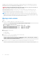
Renaming a meta-volume By default, meta-volume names are based on a timestamp. To change the name, do the following: Steps 1. Navigate to the /clusters/cluster/system-volumes/ context: VPlexcli:/> cd clusters/cluster-2/system-volumes/ VPlexcli:/clusters/cluster-2/system-volumes> 2. Use the ll command to display the names of the meta-volumes. 3. Navigate to the /clusters/cluster/system-volumes/target-meta-volume context.
A warning message appears: Meta-volume 'metadata_1' will be destroyed. Do you wish to continue? (Yes/No) 4. Type y. NOTE: After the deletion of a meta-data volume, delete the data on the storage volume through external means to avoid any future confusion.
Table 1. Metavolume display fields Field Description active Indicates whether this volume is the currently active metadata volume. The system has only one active metadata volume at a time. application-consistent Whether this storage-volume is application-consistent. block-count The number of blocks in the volume. capacity The size of the metavolume. component-count The number of mirrors in the RAID 1 metadata volume.
Table 1. Metavolume display fields (continued) Field Description system-id Name that is assigned to the metavolume. thin-capable Indicates if the volume is thin capable. Yes indicates that the volume is thin-capable. indicates that it is not thin capable. transfer-size The transfer size during rebuild in bytes. volume-type For metavolumes, it is always meta-volume.
3 System Management This chapter describes how to use the call-home notifications, event log locations, and hardware acceleration with VAAI.
Before you begin You need the following information to complete the configuration of call-home notification: ● IP address of the ESRS gateway used to forward call-home notifications to Dell EMC. Dell EMC recommends using your ESRS gateway as the primary connection address. ● (Optional) One or more IP addresses of secondary ESRS gateway server(s) used to forward call-home notifications to Dell EMC if the primary server fails.
Hardware acceleration with VAAI VMware API for Array Integration (VAAI) allows you to: ● ● ● ● Offload storage operations from compute side to storage hardware. Shift I/O intensive operations of provisioning and creating a snapshot from hypervisor to metro node. Dedicate hypervisor memory and processing resources to other functions. UNMAP unused storage blocks from thin provisioned volumes. Thin support in metro node on page 23 Provides more information on thin provisioning.
● Storage view - Enabled or disabled for all existing storage views. A storage view created after CAW is enabled/disabled at the storage view level inherits the system default setting. Dell EMC recommends maintaining uniform CAW setting on all storage views. If CAW must be disabled for a given storage view, it must be disabled for all existing and future storage views. To ensure that future storage views to reflect the new setting, change the system default (described below).
Enable/disable CAW as system default Use the set command in /clusters/cluster context to enable or disable CAW for the entire cluster. To enable CAW as the cluster system default: VPlexcli:/clusters/cluster-1> set default-caw-template true To disable CAW as the cluster system default: VPlexcli:/clusters/cluster-1> set default-caw-template false CAW statistics CAW performance statistics are included for front-end volume (fe-lu), front-end port (fe-prt), and front-end director (fedirector) targets.
CAUTION: To disable the Write Same 16 default template, you must disable Write Same 16 for all existing views, and disable Write Same 16 template so that all future views will be Write Same 16 disabled. To enable the Write Same 16 default template, you must enable Write Same 16 for all existing views, and enable Write Same 16 template so that all future views will be Write Same 16 enabled.
Enable/disable WriteSame (16) as system default Use the set command in /clusters/cluster context to enable or disable WriteSame(16) for the entire cluster.
Displaying XCOPY statistics Metro node provides statistics that track performance and frequency of XCOPY operations. These statistics are collected at the front-end. See Statistics on page 95. Setting up an XCOPY monitor For all statistics not automatically collected as a part of perpetual monitoring, you can manually create a monitor to gather statistics of XCOPY latency on a particular metro node virtual volume.
4 Thin support in metro node This chapter describes how metro node supports the thin-aware functionalities. Topics: • • • • Thin Thin Thin Thin support in metro node provisioning storage management mirroring and migration Thin support in metro node Thin-aware is the functionality of advertising metro node virtual volumes as thin volumes to hosts. Thin volumes offer more efficiency because the amount of resources used is much smaller than allocated.
virtual volume will inherit the thin capabilities of the target device. Migrating thin-capable storage provides you more information on the thin-capable storage migrations. The following table describes how metro node supports the thin-aware functionalities (based on the understanding of metro node whether the arrays are thin capable). Table 4.
Creating thin-enabled virtual volumes through the legacy provisioning method In the legacy method, you can create a thin-enabled virtual volume in these two ways: ● EZ Provisioning: Use the storage-tool compose --thin command to create a virtual-volume on top of the specified storage-volumes, building all intermediate extents, local, and distributed devices as necessary. ● Advanced provisioning: Perform these tasks: ○ Manually claiming thin storage volumes that are discovered by metro node.
block-size cache-mode capacity consistency-group expandable expandable-capacity expansion-method expansion-status health-indications health-state locality operational-status scsi-release-delay service-status storage-tier supporting-device system-id thin-capable thin-enabled volume-type vpd-id 4K synchronous 20G true 0B storage-volume [] ok local ok 0 running XtremIO_LUN_1 XtremIO_LUN_1_vol true enabled virtual-volume VPD83T3:6000144000000010e03e55ee4c98c41f NOTE: You can use wildcards to set multiple metr
● Temporary exhaustion: Occurs when a storage array is in the process of freeing up space and cannot immediately respond back with a success to the write. In such a case, metro node retries I/O for short period of time, before failing the write and marking the storage volume hardware-dead. A call home is issued in such a case and metro node tries to automatically recover the storage volume when it responds successfully to its health tests.
cause: Operation was halted by the user VPlexcli:/clusters/cluster-1/storage-elements/extents> You can attach a mirror to a device already supporting a thin-enabled virtual-volume using the device attach-mirror command. To add a thick mirror leg to a thin-enabled virtual-volume, you can continue by: ● Setting the virtual-volume's thin-enabled property to false using the set command. The new virtual-volume is not thinenabled, nor thin-capable. VPlexcli:/clusters/cluster-1/devices> set ..
5 Provisioning Storage This chapter describes how to provision storage using metro node integrated storage provisioning. Topics: • • • Provisioning Overview Provisioning storage using EZ provisioning Changing the thin personality of a virtual volume Provisioning Overview To begin using metro node, you must provision storage so that hosts can access that storage.
block-size cache-mode capacity consistency-group expandable expandable-capacity expansion-method expansion-status health-indications health-state locality operational-status scsi-release-delay service-status storage-tier supporting-device system-id thin-capable thin-enabled volume-type vpd-id 4K synchronous 20G true 0B storage-volume [] ok local ok 0 running XtremIO_LUN_1 XtremIO_LUN_1_vol true enabled virtual-volume VPD83T3:6000144000000010e03e55ee4c98c41f NOTE: You can use wildcards to set multiple metr
6 Volume expansion This chapter describes how to expand virtual volumes. Topics: • • • Overview Volume expansion method Expand the virtual volume Overview A metro node virtual volume is created on a device or a distributed device, and is presented to a host through a storage view. For a number of reasons, you may want to expand the capacity of a virtual volume. If the volume supports expansion, metro node detects the capacity gained by expansion.
------------------. . . capacity consistency-group expandable expandable-capacity expansion-method expansion-status -------------- 0.5G true 0.0G storage-volume - Note that the expansion-method attribute value storage-volume indicates that metro node uses the storage volume method to expand this virtual volume by default. List expansion-method attribute using Unisphere When using Unisphere, click on the virtual volume name to display the properties of the virtual volume you want to expand.
Expand the virtual volume Storage-volume expansion method Use the following guidelines to expand the virtual volume using the storage-volume method. Overview The storage volume method of expansion supports simple and fast expansion on a variety of device geometries. Three of the most common device geometries are described here. 1:1 virtual volume to storage volume Figure 2.
Dual-legged RAID 1 Figure 3. Common geometries: dual-legged RAID 1 Storage-volume expansion method prerequisites In order to expand a device or add a target for expansion using the storage-volume expansion method, the metro node virtual volume geometry must meet one of the following criteria: ● The virtual volume is mapped 1:1 to the underlying storage volume. ● The virtual volume is a multi-legged RAID 1 volume, and each of its smallest extents is mapped 1:1 to a back end storage volume.
CAUTION: Performing a major host operation (such as a LIP reset, for example) in order to detect a change in volume size presents risk to volumes accessed by the host. It is best to avoid such resource intensive operations during volume expansion. ● Expansion initialization traffic occurs on disk areas that are not performing host I/O. In addition, the amount of time taken to initialize the newly added capacity depends on the performance of the array hosting that is the storage volumes.
Limitations with storage-volume expansion The following limitations apply to the storage volume expansion method: ● For virtual volumes built on RAID 1 or distributed RAID 1 devices, a maximum of 1000 initialization processes can run concurrently per cluster. If this limit is reached on a cluster, then no new expansions can be started on virtual volumes with these geometries until some of the previously started initialization processes finish on that cluster.
7 Data migration This chapter describes data migrations and rebuild. Topics: • • • • • About data migrations Migrating thin-capable storage About rebuilds One-time data migrations Batch migrations About data migrations There are two types of data migrations: ● One time migrations - Begin a device migration immediately when the dm migration start command is used. ● Batch migrations - Are run as batch jobs using re-usable migration plan files.
General procedure to perform data migration Use the following general steps to perform device migrations: 1. Create and check a migration plan (batch migrations only). 2. Start the migration. 3. Monitor the migration progress. 4. Pause, resume, or cancel the migration (optional). 5. Commit the migration. Commit transfers the source virtual volume, device to the target.
Table 5. Migration scenarios (continued) Migration Virtual volume state before Virtual volume state during migration migration Virtual volume state after migration NOTE: In this case, UNMAP is intentionally disabled.
cause: Operation was halted by the user VPlexcli:/clusters/cluster-1/storage-elements/extents> ● In a thin to thick extent migration (no supported virtual volume), if the source is thin-capable and the target is not thin-capable, the source loses its thin-capability after migration.
● In a thin to thick extent migration (with no supported virtual-volumes), the metro node CLI displays a warning stating that the source loses its thin-capability after migration. VPlexcli:/> batch-migrate create-plan --file migration.txt --sources extent_thin_1, extent_thin_2 --targets extent_thick_1, extent_thick_2 Extents matching source pattern: extent_thin_1, extent_thin_2 Extents matching target pattern: extent_thick_2, extent_thick_1 Creating file /var/log/VPlex/cli/migration.
About rebuilds Rebuilds synchronize data from a source drive to a target drive. When differences arise between legs of a RAID, a rebuild updates the out-of-date leg. There are two types of rebuild behavior: ● A full rebuild copies the entire contents of the source to the target. ● A logging rebuild copies only changed blocks from the source to the target. Local mirrors are updated using a full rebuild (local devices do not use logging volumes).
Performance considerations To improve overall metro node performance, disable automatic rebuilds or modify the rebuild transfer size: ● Disable automatic rebuilds to avoid a flood of activity when re-attaching two clusters. CAUTION: Disabling automatic rebuilds prevents distributed RAID 1s from synchronizing. Child devices will be out of date, increasing the likelihood of remote reads. ● Modify the rebuild transfer size. For more information, see About transfer-size.
Monitoring a migration’s progress Use the ls command to display the migration’s status. About this task VPlexcli:/> ls data-migrations/device-migrations/ migrate_012 Name Value --------------- ---------------------------from-cluster cluster-1 percentage-done 10 source device_012 source-exported false start-time Fri May 28 13:32:23 MDT 2010 status in progress target device_012a target-exported false to-cluster cluster-2 transfer-size 12M type full Table 7.
Pausing/resuming a migration (optional) Active migrations (a migration that has been started) can be paused and then resumed at a later time. About this task Pause an active migration to release bandwidth for host I/O during periods of peak traffic. Use the dm migration pause --migrations command to pause a migration. Specify the migration-name by name if that name is unique in the global namespace. Otherwise, specify a full pathname.
NOTE: You must use the --force option to commit a migration. For example: ● Commit a device migration: VPlexcli:/data-migrations/device-migrations> dm migration commit --force --migrations migrate_012 Committed 1 data migration(s) out of 1 requested migration(s). Cleaning a migration For device migrations, cleaning dismantles the source device down to its storage volumes. The storage volumes that are no longer in use are unclaimed.
The steps to perform a batch migration are generally the same as those described in the General procedure to perform data migration. There are two additional steps to prepare for a batch migration: 1. Create a batch migration plan file (using the batch-migrate create-plan command) 2. Test the batch migration plan file (using the batch-migrate check-plan command) Prerequisites The following prerequisites are required for batch migrations: ● The source and targets are both devices.
Repeat the process of check and modify until the batch migration plan passes the plan check. For example: VPlexcli:/> batch-migrate check-plan --file migrate.txt Checking migration plan file /temp/migration_plans/migrate.txt. Plan-check passed. Modifying a batch migration file To modify a batch migration file, do one of the following: About this task ● Use the batch-migrate create-plan command, specify the same filename, and use the --force option to overwrite the old plan with the new one.
Pausing/resuming a batch migration (optional) Active batch migrations (a migration that has been started) can be paused and resumed. About this task Pause an active batch migration to release bandwidth for host I/O during periods of peak traffic. Resume the batch migration during periods of low I/O. Use the batch-migrate pause command to pause the specified active migration. For example: VPlexcli:/data-migrations/device-migrations> batch-migrate pause --file migrate.
Viewing a batch migration’s status Use the batch-migrate summary command to display the status of the specified batch migration. About this task For example: VPlexcli:/> batch-migrate summary migrate.txt Processed 10 migrations from batch migration BR0: committed: 0 complete: 10 in-progress: 0 paused: 0 error: 0 cancelled: 0 no-record: 0 Table 8. Batch migration summary Field Description Processed....
Steps 1. Use the batch-migrate summary command to verify that the migration has completed with no errors. 2. Use the batch-migrate commit --file command to commit the migration. WARNING: Commit permanently removes the volumes from the source devices. For example: VPlexcli:/> batch-migrate commit --file migrate.txt Cleaning a batch migration For device migrations, cleaning dismantles the source device down to its storage volumes. The storage volumes that are no longer in use are unclaimed.
8 Configure the WAN Network The two WAN ports on each metro node director support dual 10 Gigabit Ethernet inter-cluster links. The WAN ports are configured as part of the installation of a second cluster. This chapter describes the CLI contexts and procedures to change the configuration created during installation.
● ● ● ● wan-com - Configuration of inter-cluster connectivity. local-com - Configuration of connectivity between local directors. front-end - Configuration of connectivity with hosts. back-end - Configuration of connectivity with storage arrays. port-groups context The port groups (or communication paths) assigned to each connectivity role (back-end, front-end, local-com or wan-com) are contained in the port-groups sub-context of each role.
IP port-groups contain: ● option-set context contains configuration options common to the member ports. ● subnet context contains configuration options for IP networking. Different roles have different networking needs, and thus their subnet contexts contain different properties. These subnets are descried under their associated role. ● enabled - Summarizes the enabled status of the individual member ports. Member ports All properties under the member-ports context are read-only.
● prefix must contain the gateway. ● gateway must be a unique address on the local cluster. Note the following: ● A cleared address is contained by all prefixes and matches no addresses. ● A cleared prefix contains all addresses. ● A property that is not present in a particular subnet context is considered cleared. If a change is made to the subnet, the change is validated and applied to all ports using this subnet.
/connectivity/local-com/ The local role context contains the configuration information related to inter-director communication within the current cluster. The local role does not have any associated properties. Managing and Monitoring back-end network For high availability each director should have multiple paths to each storage volume. Environmental issues such as network congestion or array problems can affect the availability and performance of these paths.
LDAP The Lightweight Directory Access Protocol (LDAP) is an application protocol for accessing and maintaining distributed directory information services over an Internet Protocol (IP) network. Directory services provides any organized set of records with a hierarchical structure. LDAP is a client-server model protocol. Directory structure The organization of a directory is a tree structure. The top most entry in a directory is known as the root entry.
member: uid=QE2,ou=gui,ou=qe,ou=vplex,dc=emc,dc=com member: uid=dev3,ou=GUI,ou=dev,ou=vplex,dc=emc,dc=com ● To determine the attributes of the user principal in the case of Open LDAP server: service@ManagementServer:~> /usr/bin/ldapsearch -x -LLL -l 30 -H ldap:// 10.31.50.
9 Consistency Groups This chapter describes how to manage and operate metro node consistency groups. Topics: • • • • About metro node consistency groups Properties of consistency groups Manage consistency groups Operating a consistency group About metro node consistency groups Metro node consistency groups aggregate volumes to enable the application of a common set of properties to the entire group. Figure 5.
Figure 6. Synchronous consistency group ● The hosts at both clusters write to the metro node distributed volumes in the consistency group. ● Metro node writes data to the back-end storage on both clusters ● An acknowledgment is returned to the host that is issuing the write. This guarantees that the image on the back end storage is an exact copy on both sides.
Figure 7. Local consistency groups with local visibility Global visibility If the local consistency groups have their Visibility property set to both clusters (global visibility), both clusters can receive I/O from the cluster that does not have a local copy. All writes from that remote cluster pass over the inter-cluster WAN link before they are acknowledged. Any reads that cannot be serviced locally are also transferred across the link.
Figure 8. Local consistency group with global visibility Properties of consistency groups Properties of a consistency group are applied to all the virtual volumes in the consistency group. All consistency groups have configurable properties that determine I/O behavior, including: ● ● ● ● ● Visibility Storage-at-clusters Detach-rule Auto-resume-at-loser Virtual-volumes Visibility Visibility controls which clusters know about a consistency group.
When a consistency group’s visibility is set to a cluster, the consistency group appears below /clusters/cluster-n/ consistency-groups context for the cluster. NOTE: The context for a specified consistency group appears in a cluster’s consistency group CLI context only if the Visibility property of the consistency group includes that cluster. Under normal operations, the visibility property can be modified to expand from one cluster to both clusters.
Detach-rule Detach rules are a consistency group’s policy for automatically picking a winning cluster when there is an inter-cluster link outage. For metro node Metro configurations, there are two consistency group detach rules: ● no-automatic-winner - The consistency group does not select a winning cluster. ● winner cluster-name delay seconds - The cluster specified by cluster-name is declared the winner if an intercluster link outage lasts more than the number of seconds specified by delay.
Auto-resume-at-loser Determines whether the loser automatically resumes I/O when the inter-cluster link is repaired after a failure. When the link is restored, the losing cluster finds out that the data on the winning cluster is different. The loser must determine whether to suddenly change to the winner's data, or to keep suspending I/O. By default, auto-resume is enabled. Usually, this property is set to false to give the administrator time to halt and restart the application.
Manage consistency groups NOTE: A key best practice for creating and managing consistency groups is to create a 1:1 relationship between consistency groups and applications. All volumes (and only those volumes) required for an application should be in a single consistency group.
To set the consistency group’s visibility property to both clusters: VPlexcli:/clusters/cluster-1/consistency-groups> set TestCG::visibility cluster-1,cluster-2 To set the consistency group’s visibility property to cluster-1: VPlexcli:/clusters/cluster-1/consistency-groups> set TestCG::visibility cluster-1 To set the consistency group’s visibility property to cluster-2: VPlexcli:/clusters/cluster-1/consistency-groups> set TestCG::visibility cluster-2 Setting the storage-at-clusters property By default, the
Steps 1. Navigate to the target consistency group’s context: VPlexcli:/> cd clusters/cluster-1/consistency-groups/TestCG 2. Use the consistency-group list-eligible-virtual-volumes command to display virtual volumes that are eligible to be added to the consistency group: VPlexcli:/clusters/cluster-1/consistency-groups/TestCG> consistency-group listeligible-virtual-volumes [TestDDevice-1_vol, TestDDevice-2_vol, TestDDevice-3_vol, TestDDevice-4_vol, TestDDevice-5_vol] 3.
To remove multiple virtual volumes with a single command, separate the volumes using commas: VPlexcli:/> consistency-group remove-virtual-volumes /clusters/cluster-1/virtualvolumes/TestDDevice-2_vol, /clusters/cluster-1/virtual-volumes/TestDDevice-3_vol -consistency-group /clusters/cluster-1/consistency-groups/TestCG Remove two virtual volumes from the target consistency group context: VPlexcli:/clusters/cluster-1/consistency-groups/TestCG> remove-virtual-volumes TestDDevice-2_vol, TestDDevice-3_vol 3.
virtual-volumes visibility context pattern. Read-only. Takes a list with each element being a 'cluster' context or a To display the current setting of a property: VPlexcli:/> set /clusters/cluster-1/consistency-groups/TestCG::cache-mode To display the default values for the target consistency group: VPlexcli:/clusters/cluster-1/consistency-groups/TestCG> set --default attribute default-value -------------------- ----------------active-clusters No default value. cache-mode synchronous.
To apply a detach rule that will determine the behavior of all volumes in a consistency group: Steps 1. Use the ll command to display the current detach rule (if any) applied to the consistency group: VPlexcli:/clusters/cluster-1/consistency-groups/TestCG2> ll Attributes: Name Value -------------------- ---------------------active-clusters [] cache-mode synchronous detach-rule . . . 2.
To delete a consistency group from the root context: VPlexcli:/> consistency-group destroy clusters/cluster-1/consistency-groups/TestCG WARNING: The following items will be destroyed: Context --------------------------------------------/clusters/cluster-1/consistency-groups/TestCG Do you wish to proceed? (Yes/No)Yes To delete a consistency group from the consistency group context: VPlexcli:/clusters/cluster-1/consistency-groups> destroy TestCG WARNING: The following items will be destroyed: Context --------
RAM_RR_cluster-2 winner synchronous . . . details:: [] }), (cluster-2,{ summary:: unknown, details:: [] }) (cluster-1,{ summary:: ok, no-automatic- details:: [] }), (cluster-2,{ summary:: ok, details:: [] }) Use the ls command in the /clusters/cluster-name/consistency-groups/consistency-group context to display the operational status of the groups.
}), (cluster-2,{ summary:: suspended, details:: [cluster-departure] })] passive-clusters [] recoverpoint-enabled false storage-at-clusters [cluster-1, cluster-2] virtual-volumes [dd1_vol, dd2_vol] visibility [cluster-1, cluster-2] Contexts: advanced recoverpoint ● The ls command shows consistency group cg1 as suspended, requires-resume-at-loser on cluster-2 after cluster-2 is declared the losing cluster during an inter-cluster link outage. ● The resume-at-loser command restarts I/O on cluster-2.
Table 11. Consistency group field descriptions (continued) Property Description ● winner - The cluster specified by cluster-name will be declared the winner if an inter-cluster link outage lasts more than the number of seconds specified by delay. storage-at-clusters The cluster where the physical storage associated with a consistency group is located. ● Modifiable using the set command.
Table 11. Consistency group field descriptions (continued) Property Description operational status Current status for this consistency group with respect to each cluster on which it is visible. ● ok - I/O can be serviced on the volumes in the consistency group. ● suspended - I/O is suspended for the volumes in the consistency group. The reasons are described in operational status: details. ● degraded - I/O is continuing, but there are other problems as described in operational status: details.
When the inter-cluster link is restored, the clusters learn that I/O has proceeded independently. I/O continues at both clusters until you pick a winning cluster whose data image will be used as the source to synchronize the data images. In the following example, I/O resumed at both clusters during an inter-cluster link outage. When the inter-cluster link is restored, the two clusters come back into contact and learn that they have each detached the other and carried on I/O. Steps 1.
Resuming I/O after rollback About this task Without that data, the winning cluster's data image is inconsistent. Resuming I/O at the winner requires rolling back the winner's data image to the last point where the clusters agreed. This can cause a sudden change in the data image. Many applications cannot tolerate sudden data changes, so the roll-back and resumption of I/O requires manual intervention. The delay gives the administrator the chance to halt applications before changing the data image.
Resuming I/O at the losing cluster During an inter-cluster link outage, an you might permit I/O to resume at one of the two clusters, the winning cluster. About this task I/O remains suspended on the losing cluster. When the inter-cluster link restores, the winning and losing clusters re-connect, and the losing cluster discovers that the winning cluster has resumed I/O without it. Unless explicitly configured, I/O remains suspended on the losing cluster.
Contexts: advanced recoverpoint You might notice rebuilding-across-clusters in operational status while devices are rebuilding. Setting the read-only attribute SRDF R2 devices (replicas) are an example of an array-managed Business Continuance Volume (BCV). For consistency groups that contain these volumes, you can use the set command to set the consistency group to read-only.
10 Performance and Monitoring This chapter describes RPO/RTO and the procedures to create and operate performance monitors.
Custom monitors You can use the CLI to create custom monitors to collect and display selected statistics for selected targets. See Monitor performance using the CLI. Perpetual monitors GeoSynchrony includes perpetual monitors that gather a standard set of performance statistics every 30 seconds. Perpetual monitors collect the statistics related to the performance of metro node directors and virtual volumes. Perpetual monitor files are collected as part of collect-diagnostics.
Performance monitoring using Unisphere for metro node The performance monitoring dashboard provides a customized view into the performance of your system. You decide which aspects of the system's performance to view and compare. Figure 9. Performance monitoring dashboard (for HTML5) Performance information for the current 5-minute window is displayed as a set of charts, including: ● WAN Link Performance chart - Shows the WAN link performance for the cluster to you are connected to.
● Virtual Volume Bandwidth chart - Provides a time-based view of the total bandwidth (or KB/s or MB/s) in reads and writes for a virtual-volume. Generally bandwidth (also referred to as KB/s or MB/s), is associated with large block I/O (64KB or greater I/O requests) ● Front-end ports dashboard - Displays performance metrics for all metro node front-end ports. The dashboard does not provide historical data, but refreshes every five seconds and displays data from the previous five-second period.
Specify only one type of target per monitor. For example, you cannot create a monitor that includes both port and storage volumes as targets. 2. Determine how often the monitor should collect statistics. 3. Use the monitor create command to create a monitor. 4. Use the monitor add-sink commands to add one or more sinks to the monitor. ● Add a console sink to send performance data to the metro node management console. ● Add a file sink to send performance data to a specified file. 5.
Create a perfomance monitor to monitor local COM latency for a specified director: VPlexcli:/> monitor create --name local-cluster --stats "com-cluster-io.*" --director director-1-1-A --targets "/clusters/cluster-1" Create a perfomance monitor to monitor latency to the remote cluster: VPlexcli:/> monitor create --name remote-cluster --stats "com-cluster-io.
To add a file sink to send output to the specified .csv file: VPlexcli:/monitoring/directors/director-1-1-A/monitors> monitor add-file-sink director-1-1-A_stats --file /var/log/VPlex/cli/director_1_1_A.
SNMPTestMonitor --director director-1-1-B --stats fe-lu.read,fe-lu.read-lat,felu.write,fe-lu.write-lat,fe-lu.ops --targets /clusters/cluster-1/virtual-volumes/ polyvol_e4_extent_Symm0487_393 Successfully created 1 monitor(s) out of 1.
targets DR1_C1-C2_1gb_dev10_vol, DR1_C1-C2_1gb_dev12_vol, DR1_C1-C2_1gb_dev14_vol, DR1_C1-C2_1gb_dev16_vol, DR1_C1-C2_1gb_dev18_vol, total) DR1_C1-C2_1gb_dev11_vol, DR1_C1-C2_1gb_dev13_vol, DR1_C1-C2_1gb_dev15_vol, DR1_C1-C2_1gb_dev17_vol, DR1_C1-C2_1gb_dev19_vol, ... (1300 Contexts: Name Description ----- -----------------------------------------------------------------------sinks Contains all of the sinks set up to collect data from this performance monitor.
Use the set command to disable, or modify automatic polling for a monitor.
Force an immediate poll Use the monitor collect command to force an immediate poll and collection of performance data without waiting for the automatic poll interval. For example: VPlexcli:/> monitor collect /monitoring/directors/director-2-1-B/monitors/director-2-1B_TestMonitor Source: Time: director.be-ops (counts/s): . . . director-2-1-B_TestMonitor 2010-07-01 10:05:55 Port Monitoring Details related to port-stats-monitor script.
Checking the script status Steps 1. Check the status of the script to see if it is running. VPlexcli:/> port-monitor status Status: running with the following parameters: Emails: joe@dell.com SMTP: x.x.x.x Local-only: False 2.
it reads "Checking status" and only run that command for now. Steps c and d are to be followed for both clusters if a Metro. c. Changing default thresholds in the config.json file (optional). If you find that the default values, or one of them, could be increased for better results, you can modify the config.json file for new threshold values (using VI editor). Example: vim /var/log/VPlex/cli/port-stats-monitor/config.json.
VPlexcli:/> port-monitor start -e example@emc.com Starting port stat monitor... ### Stopping the monitor To stop the monitor, run `port-monitor stop`. ### Checking status To see whether or not the monitor is running, or to see if any unexpected errors were encountered, run the `port-monitor status` command: VPlexcli:/> port-monitor status Status: running with the following parameters: Emails: None SMTP: x.x.x.
director-1-1-B B0-FC00 (front-end) crc-errors has increased by 15254 director-1-1-B B0-FC01 (front-end) crc-errors has increased by 953630 Things to note Take note of the number of ports and the number of directors reporting issues. For instance, if half of the ports are reporting issues, then it may indicate a fabric-wide event. Whereas if only one port is reporting an error, then the problem is localized to a specific I-T Nexus.
○ Counters are used to count bytes, operations, and errors. ○ Often reported as a rate such as counts/second or KB/second. ● readings - Instantaneous value (analogous to a car’s speedometer) ○ Readings are used to display CPU utilization, memory utilization. ○ Value can change every sample. ● period-average - Average of a series calculated over the last sample period. If: ○ current_reading_sum is the sum of all readings for the particular statistic since the monitor's creation.
cg.drain-lat cg.exch-bytes cg.exch-lat cg.exch-pages cg.input-bytes cg.input-ops cg.inter-closure cg.outOfDate-counter cg.pipe-util cg.write-bytes cg.write-lat cg.write-pages . . .
● ● ● ● ● ● ● ● ● ● ● ● Front-end volume (fe-lu) statistics Front-end port (fe-prt) statistics Remote RAID (ramf) statisticsRemote RAID (ramf) statistics Storage-volume statistics Virtual-volume statistics IP WAN COM (ip-com-port) statistics - Monitors IP ports (any port with GE or XG in the port name). IP Congestion Control Statistics COM cluster I/O statistics COM Path statistics COM Endpoint Statistics XCOPY Statistics Host Initiator Statistics Table 14.
Table 15. Director statistics (continued) Statistic Type Description director.be-write Back-end writes Number of bytes written by the director’s back-end ports. Back-end WriteSame Back-end WriteSame details. CPU Percentage of CPU usage. Communication bytes active Number of bytes active to a remote director. Communication bytes queued Number of bytes queued to a remote director. Communication operations active Number of operations active to a remote director.
Table 15. Director statistics (continued) Statistic Type Description director.fe-read Front-end reads Number of bytes read from the director’s front-end ports. Front-end writes Number of bytes written to the director’s front-end ports. Memory Percentage of memory usage on the director. CPU busy The total utilization (user and system) of each CPU in the director. director.msg-send-ops number of operations The total number of messages sent from this director. director.
Table 16. Front-end director (fe-director) statistics (continued) Statistic Type Description type: period-average, units:us, arguments: none Table 17. Front-end volume (fe-lu) statistics Statistic Type Description fe-lu.caw-lat CompareAndWrite operations latency CompareAndWrite latency in microseconds on the specified front-end volume. CompareAndWrite miscompares Number of CompareAndWrite miscompares on the specified front-end volume.
Table 18. Front-end port (fe-prt) statistics Statistic Type Description fe-prt.caw-lat CompareAndWrite operations latency CompareAndWrite latency in microseconds on the specified front-end port. CompareAndWrite miscompares Number of CompareAndWrite miscompares on the specified front-end port. CompareAndWrite operations Number of CompareAndWrite operations on the specified front-end port. Front-end port operations Number of I/O operations on the specified front-end FC port.
Table 19. Remote RAID (ramf) statistics (continued) Statistic Type Description ramf.exp-op Remote operations Total number of remote IOPS. Remote reads Remote reads from another cluster to a disk or LUN at the local cluster. Remote writes Remote writes from another cluster to a disk or LUN at the local cluster. Imported ops Number of operations that have been requested by a given director, regardless of remote target.
Table 20. Storage-volume statistics (continued) Statistic Type Description Statistic Type Description virtual-volume.dirty Volume dirty Number of modified pages in cache for the specified virtual volume. Volume operations Total number of I/O operations for the specified virtual volume. Volume reads Number of reads in bytes for the specified virtual volume. Volume writes Number of writes in bytes for the specified virtual volume. type: period-average, units: us, arguments: none Table 21.
Table 22. IP WAN COM (ip-com-port) statistics (continued) Statistic Type Description ip-com-port.recv-frame-errors IP WAN COM Port received frames Number of frames received on this IP WAN COM Port ip-com-port.send-carrier-errors IP WAN COM Port send carrier Number of carriers sent on this IP WAN COM Port ? ip-com-port.collisions IP WAN COM Port collisions Number of collisions on this IP WAN COM Port Table 23. IP Congestion Control Statistics Statistic Description ip-congestion-control.
Table 25. COM I/O group statistics (continued) Statistic Description com-io-group.io-tm-min Minimum latency on this channel group in last 5 seconds (updated every 5 seconds). com-io-group.msg-b-in Always returns zero. com-io-group.msg-b-out Total bytes sent on this channel group. com-io-group.msg-cnt-in Always returns zero. com-io-group.msg-cnt-out Total messages sent on this channel group. Table 26. COM Path Statistics Statistic Description com-path.ping-count Number of ping packets sent.
Table 27. COM Endpoint Statistics (continued) com-endpoint.data-pckts-badlen Number of invalid data packet length. com-endpoint.data-pckts-recv Number of data packets received. com-endpoint.data-pckts-routed Number of routed data packets. com-endpoint.data-pckts-runt Number of data packets that are less than 64 bytes long. com-endpoint.data-pckts-sent Number of data packets sent. com-endpoint.rx-ack-buf-pend-pckts Number of pending ack buffers to be processed.
A Metro node with active-passive storage arrays Topics: • • • • Active-passive array ALUA mode enabled array Logical Unit failover execution Logical Unit failback Active-passive array An active-passive array typically has two controllers and provides active-passive access to a Logical Unit (LU) through a set of target ports. The access types of these ports are Active (ACT) or Passive (PAS). Active is used for I/O and passive cannot be used for I/O.
When failover is initiated for a specific logical unit on an array to a specific target controller as active, metro node firmware event apf/3 is observed. When failover succeeds or fails for a specific logical unit on an array to a specific target controller as active, a metro node firmware event apf/4 is generated. For Example: apf/3 Failover initiated for logical unit VPD83T3:6006016015a0320061d7f2b300d3e211 on array EMC~CLARiiON~FNM00124500474 to target controller FNM00124500474.SPA as active.
Index A D About:meta-volumes 9 Active-passive array 108 ALUA mode enabled array 108 attaching a mirror 27 data migrations:about 37 data migrations:batch migrations 37 data migrations:general steps 38 data migrations:one time migrations 37 data migrations:prerequisites 38 data:migration, batching;data:migration, multiple RAIDs; migrating data:multiple RAIDs; RAIDs: migrating (batching) 46 Display:monitors 87 B batch batch batch batch batch batch batch batch batch batch batch migrations 46 migrations:can
Performance monitoring:delete monitor sink 87 Performance monitoring:display monitors 87 Performance monitoring:display statistics 96 Performance monitoring:file rotation 84 Performance monitoring:force an immediate poll 91 Performance monitoring:manage sinks 90 Performance monitoring:polling 89 Performance monitoring:procedure 84 Performance monitoring:statistics 95 Performance monitoring:using the VPLEX CLI 84 Performance monitoring:VPLEX GUI 83 port groups 52 port-groups context 53 R rebuilds 42 rebuild