Dell™ PowerVault™ NX1950 Systems Hardware Owner's Manual About Your System Using the System Setup Program Installing System Components Troubleshooting Your System Running the System Diagnostics Jumpers and Connectors Getting Help Glossary Model EMU01 Notes, Notices, and Cautions NOTE: A NOTE indicates important information that helps you make better use of your computer. NOTICE: A NOTICE indicates either potential damage to hardware or loss of data and tells you how to avoid the problem.
Back to Contents Page About Your System Dell™ PowerVault™ NX1950 Systems Hardware Owner's Manual Other Information You May Need LCD Status Messages Accessing System Features During Startup System Messages Front-Panel Features and Indicators Warning Messages Back-Panel Features and Indicators Diagnostics Messages Power Indicator Codes Alert Messages NIC Indicator Codes This section describes the physical, firmware, and software interface features that provide and ensure th
allows you to configure NIC settings for PXE boot. For more information, see the documentation for your integrated NIC. This keystroke allows access to selected Dell remote access controller (DRAC) configuration settings. See the DRAC User's Guide for more information on setup and use of DRAC. Front-Panel Features and Indicators Figure 1-1 shows the controls, indicators, and connectors located behind the optional rack bezel on the system's front panel. Figure 1-1.
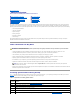
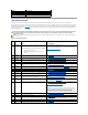
Figure 1-2. Hard-Drive Indicators 1 drive-status indicator (green and amber) 2 green drive-activity indicator Table 1-3 lists the drive indicator patterns. Different patterns are displayed as drive events occur in the system. For example, if a hard-drive fails, the "drive failed" pattern appears. After the drive is selected for removal, the "drive being prepared for removal" pattern appears, followed by the "drive ready for insertion or removal" pattern.
l Most devices must be connected to a specific connector and device drivers must be installed before the device operates properly. (Device drivers are normally included with your operating system software or with the device itself.) See the documentation that accompanied the device for specific installation and configuration instructions. l Always attach external devices while your system is turned off.
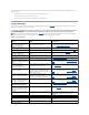
Indicator Indicator Code Link and activity indicators are off The NIC is not connected to the network. Link indicator is green The NIC is connected to a valid link partner on the network. Activity indicator is amber blinking Network data is being sent or received. LCD Status Messages The system's control panel LCD provides status messages to signify when the system is operating correctly or when the system needs attention.
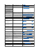
error. E1422 CPU Machine Chk The system BIOS has reported a machine check error. See Getting Help. E1610 PS # Missing No power is available from the specified power supply; specified power supply is improperly installed or faulty. See Troubleshooting Power Supplies. E1614 PS # Status No power is available from the specified power supply; specified power supply is improperly installed or faulty. See Troubleshooting Power Supplies.
Controller E2017 Timer Fail Timer refresh failure. See Getting Help. E2018 Prog Timer Programmable interval timer error. See Getting Help. E2019 Parity Error Parity error. See Getting Help. E201A SIO Err SIO failure. See Getting Help. E201B Kybd Controller Keyboard controller failure. See Getting Help. E201C SMI Init System management interrupt (SMI) initialization failure. See Getting Help. E201D Shutdown Test BIOS shutdown test failure. See Getting Help.
Any of these actions will remove fault messages, and return the status indicators and LCD colors to the normal state. Messages will reappear under the following conditions: l The sensor returns to a normal state but fails again, resulting in a new SEL entry. l The system is reset and new error events are detected. l A failure is recorded from another source that maps to the same display entry. System Messages System messages appear on the screen to notify you of a possible problem with the system.
Keyboard Controller failure Faulty keyboard controller; faulty system board See Getting Help. Manufacturing mode detected System is in manufacturing mode. Reboot to take the system out of manufacturing mode. MEMBIST failure - The following DIMM/rank has been disabled by BIOS: DIMM x Rank y Faulty memory module(s). See Troubleshooting System Memory. Memory address line failure at address, read value expecting value Faulty or improperly installed memory modules. See Troubleshooting System Memory.
The following DIMMs are not compatible: DIMM x and DIMM y The specified DIMM(s) are incompatible with the system. Ensure that only ECC FBD1 memory is used. Dell recommends purchasing memory upgrade kits directly from www.dell.com or your Dell sales agent to ensure compatibility. Time-of-day not set - please run SETUP program Incorrect Time or Date settings; faulty system battery. Check the Time and Date settings. See Using the System Setup Program. If the problem persists, replace the system battery.
Back to Contents Page Running the System Diagnostics Dell™ PowerVault™ NX1950 Systems Hardware Owner's Manual Using Server Administrator Diagnostics System Diagnostics Features When to Use the System Diagnostics Running the System Diagnostics System Diagnostics Testing Options Using the Custom Test Options If you experience a problem with your system, run the diagnostics before calling for technical assistance.
Click the testing option in the Main Menu window. Table 5-1 provides a brief explanation of testing options. Table 5-1. System Diagnostics Testing Options Testing Option Function Express Test Performs a quick check of the system. This option runs device tests that do not require user interaction. Use this option to quickly identify the source of your problem. Extended Test Performs a more thorough check of the system. This test can take an hour or longer. Custom Test Tests a particular device.
Back to Contents Page Getting Help Dell™ PowerVault™ NX1950 Systems Hardware Owner's Manual Technical Assistance Dell Enterprise Training and Certification Problems With Your Order Product Information Returning Items for Warranty Repair or Credit Before You Call Contacting Dell Technical Assistance If you need assistance with a technical problem, perform the following steps: 1. Complete the procedures in Troubleshooting Your System. 2.
support.jp.dell.com (Japan only) support.euro.dell.com (Europe only) l Electronic Quote Service apmarketing@dell.com (Asian/Pacific countries only) sales_canada@dell.com (Canada only) AutoTech Service Dell's automated technical support service—AutoTech—provides recorded answers to the questions most frequently asked by Dell customers about their portable and desktop computer systems. When you call AutoTech, use your touch-tone telephone to select the subjects that correspond to your questions.
5. Pack the equipment to be returned in the original (or equivalent) packing materials. You are responsible for paying shipping expenses. You are also responsible for insuring any product returned, and you assume the risk of loss during shipment to Dell. Collect-on-delivery (C.O.D.) packages are not accepted. Returns that are missing any of the preceding requirements will be refused at our receiving dock and returned to you. Before You Call NOTE: Have your Express Service Code ready when you call.
Website: www.dell.com.ai Anguilla E-mail: la-techsupport@dell.com Technical Support Website: www.dell.com.ag Antigua and Barbuda E-mail: la-techsupport@dell.com Technical Support Aomen Country Code: 54 City Code: 11 0800-105 E-mail for servers and EMC® storage products: la_enterprise@dell.com Customer Care Technical Support Website: www.dell.com.aw E-mail: la-techsupport@dell.
International Access Code: 00 Customer Care and Tech Support 0800 90 3355 Technical Support Fax 51 2104 5470 Country Code: 55 Customer Care Fax City Code: 51 Sales British Virgin Islands General Support Brunei Country Code: 673 International Access Code: 011 toll-free: 1-866-278-6820 Technical Support (Penang, Malaysia) 604 633 4966 Customer Care (Penang, Malaysia) 604 633 4888 Transaction Sales (Penang, Malaysia) 604 633 4955 Online Order Status: www.dell.
Czech Republic (Prague) International Access Code: 00 Country Code: 420 E-mail: czech_dell@dell.com 22537 2727 Customer Care 22537 2707 Fax 22537 2714 Technical Fax 22537 2728 Switchboard 22537 2711 Website: support.euro.dell.
Global Segment Customer Care 069 9792-7320 Preferred Accounts Customer Care 069 9792-7320 Large Accounts Customer Care 069 9792-7320 Public Accounts Customer Care 069 9792-7320 Switchboard 069 9792-7000 Country Code: 49 City Code: 69 Website: support.euro.dell.
International Access Code: 00 Fax 02 696 821 13 Switchboard 02 696 821 12 Country Code: 39 Corporate City Code: 02 Technical Support 02 577 826 90 Customer Care 02 577 825 55 Fax 02 575 035 30 Switchboard E-mail: la-techsupport@dell.com 02 577 821 toll-free: 1-800-326-6061 or Jamaica Technical Support (dial from within Jamaica only) toll-free: 1-800-975-1646 Website: support.jp.dell.
Technical Support (TelMex) Mexico toll-free: 1-866-563-4425 50-81-8800 Sales or 01-800-888-3355 International Access Code: 00 001-877-384-8979 Customer Service Country Code: 52 or 001-877-269-3383 50-81-8800 Main or 01-800-888-3355 E-mail: la-techsupport@dell.com Montserrat General Support E-mail: la-techsupport@dell.com toll-free: 1-866-278-6822 Netherlands Antilles General Support Website: support.euro.dell.
St. Kitts and Nevis E-mail: la-techsupport@dell.com Technical Support Website: www.dell.com/lc St. Lucia E-mail: la-techsupport@dell.com Technical Support Website: www.dell.com/vc St. Vincent and the Grenadines E-mail: la-techsupport@dell.com Technical Support toll-free: 1-866-540-3355 toll-free: 1-866-464-4352 toll-free: 1-866-464-4353 NOTE: The phone numbers in this section should be called from within Singapore or Malaysia only. Singapore (Singapore) Website: support.ap.dell.
00 Country Code: 41 City Code: 22 Taiwan International Access Code: 002 Country Code: 886 Technical Support (Corporate) 0844 822 844 Customer Care (Home and Small Business) 0848 802 202 Customer Care (Corporate) 022 799 01 90 Switchboard 022 799 01 01 Website: support.ap.dell.com E-mail: ap_support@dell.
U.S.A.
Back to Contents Page Glossary Dell™ PowerVault™ NX1950 Systems Hardware Owner's Manual This section defines or identifies technical terms, abbreviations, and acronyms used in your system documents. A — Ampere(s). AC — Alternating current. ACPI — Advanced Configuration and Power Interface. A standard interface for enabling the operating system to direct configuration and power management. ambient temperature — The temperature of the area or room where the system is located.
DVD — Digital versatile disc. ECC — Error checking and correction. EEPROM — Electronically erasable programmable read-only memory. EMC — Electromagnetic compatibility. EMI — Electromagnetic interference. ERA — Embedded remote access. ERA allows you to perform remote, or "out-of-band," server management on your network server using a remote access controller. ESD — Electrostatic discharge. ESM — Embedded server management.
LAN — Local area network. A LAN is usually confined to the same building or a few nearby buildings, with all equipment linked by wiring dedicated specifically to the LAN. lb — Pound(s). LCD — Liquid crystal display. LED — Light-emitting diode. An electronic device that lights up when a current is passed through it. LGA — Land grid array. A type of processor socket. Unlike the PGA interface, the LGA interface has no pins on the chip; instead, the chip has pads that contact pins on the system board.
modem. readme file — A text file, usually shipped with software or hardware, that contains information supplementing or updating the product's documentation. read-only file — A read-only file is one that you are prohibited from editing or deleting. ROM — Read-only memory. Your system contains some programs essential to its operation in ROM code. A ROM chip retains its contents even after you turn off your system.
Windows 2000 — An integrated and complete Microsoft Windows operating system that does not require MS-DOS and that provides advanced operating system performance, improved ease of use, enhanced workgroup functionality, and simplified file management and browsing. Windows Powered — A Windows operating system designed for use on NAS systems. For NAS systems, the Windows Powered operating system is dedicated to file service for network clients.
Back to Contents Page Installing System Components Dell™ PowerVault™ NX1950 Systems Hardware Owner's Manual Recommended Tools Processors Inside the System RAC Card Removing and Replacing the Front Bezel Optical Drive Opening and Closing the System Hard Drives Cooling Fan Modules Replacing a Hard-Drive Carrier Cooling Shrouds Expansion-Card Riser Power Supplies Backplane Board SAS Controller Daughter Card Sideplane Board Expansion Cards System Battery
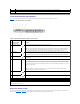
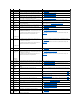
In Figure 3-1, the bezel, system cover, and memory cooling shroud are removed to provide an interior view of the system. Figure 3-1. Inside the System 1 control panel 2 SAS RAID controller daughter card 3 sideplane 4 cooling fan modules (4) 5 power supply bays (2) 6 left riser (slot 2) 7 center riser (slot 1) 8 battery 9 system board cooling shroud 10 memory modules (8) 11 heatsink/microprocessor (2) 12 backplane 13 two 3.
1 key lock 2 bezel cover To replace the front bezel, perform the preceding steps in reverse. Opening and Closing the System CAUTION: Only trained service technicians are authorized to remove the system cover and access any of the components inside the system. See your Product Information Guide for complete information about safety precautions, working inside the computer, and protecting against electrostatic discharge. CAUTION: Whenever you need to lift the system, get others to assist you.
1 latch 2 latch release lock 3 alignment J hooks 4 chassis tabs Closing the System 1. 2. Lift up the latch on the cover. Place the cover on top of the system and offset the cover slightly back so that it clears the chassis J hooks and lays flat on the system chassis. See Figure 3-3. 3. Lower the cover into the closed position aligning it with the J hooks and push down on the latch to guide the cover into place. 4.
Replacing a Cooling Fan Module NOTE: The procedure for installing each individual fan is the same. 1. Ensure that the fan handle is upright and lower the fan into its retention base until the fan is fully seated. Then lower the fan handle until it snaps into place. See Figure 3-4. 2. Attach the fan module connectors. 3. If you removed the memory cooling shroud to access the fan modules, replace the shroud. See Replacing the Memory Cooling Shroud. 4. Close the system.
1. To remove the cooling shroud, locate the release tab on the shroud edge that is nearest to the adjacent system board shroud. See Figure 3-6. 2. Pull up on the release tab to release the memory cooling shroud. 3. Unseat the shroud from the securing tabs located on the periphery of the shroud. 4. Carefully lift the shroud straight up to disengage it from the system board, and then lift the shroud away from the system. Figure 3-6.
4. Holding the power-supply handle, pull the power supply straight out to clear the chassis. Figure 3-7. Removing and Installing a Power Supply 1 power-supply 2 power-supply handle 3 cable retention bracket 4 power supply blank 5 power-supply bay 2 6 redundant power supply bay 1 7 locking tab Replacing a Power Supply 1. Holding the power-supply handle, slide the new power supply into the chassis until it is fully seated and contacts the system chassis. See Figure 3-7.
3. Slide the daughter card tray towards the sideplane until the edge connector on the daughter card fits into the socket on the sideplane board and the release latch engages. See Figure 3-8. Figure 3-8. Installing a SAS Controller Daughter Card 1 SAS controller daughter card and tray assembly 2 sideplane 3 daughter card socket 4 release latch 5 RAID battery connector 6 RAID memory module (DIMM) 7 SAS RAID connector 0 (to backplane SAS A) 8 alignment slots in card tray (2) 4.
3. Connect the battery cable to the RAID controller daughter card. See Figure 3-10. Figure 3-10. Installing a SAS RAID Battery 1 RAID battery 2 SAS RAID daughter card battery connector 3 release latch Removing a RAID Battery 1. Disconnect the RAID battery cable from the SAS RAID daughter card. See Figure 3-10. 2. Press the release latch toward the hard-drive bays and remove the battery from the battery pocket.
5. Install the expansion card: a. Position the expansion card so that the card-edge connector aligns with the expansion-card connector on the PCI riser board. b. Insert the card-edge connector firmly into the expansion-card connector until the card is fully seated. c. When the card is seated in the connector, close the expansion-card latch. See Figure 3-11. Figure 3-11.
The memory module sockets are divided into two equal branches (0 and 1). Each branch consists of two channels: l Channel 0 and channel 1 are in branch 0. l Channel 2 and channel 3 are in branch 1. Each channel consists of two memory module sockets: l Channel 0 contains DIMM_1, DIMM_5. l Channel 1 contains DIMM _2, DIMM_6. l Channel 2 contains DIMM_3, DIMM_7. l Channel 3 contains DIMM _4, DIMM _8. The first DIMM socket of each channel has white release tabs.
1. Open the system. See Opening and Closing the System. 2. Remove the memory cooling shroud. See Removing the Memory Cooling Shroud. 3. Locate the memory module sockets. See Figure 6-2. 4. Press the ejectors on the memory module socket down and out, as shown in Figure 3-12, to allow the memory module to be inserted into the socket. 5. Handle each memory module only on either card edge, ensuring not to touch the middle of the memory module. Figure 3-12.
4. Press down and out on the ejectors on each end of the socket until the memory module pops out of the socket. See Figure 3-12. Handle each memory module only on either card edge, ensuring not to touch the middle of the memory module. 5. Replace the memory cooling shroud. See Replacing the Memory Cooling Shroud. 6. Close the system. See Opening and Closing the System.
1 heat sink 2 heat-sink retention lever (2) 3 retention lever latch 6. Wait 30 seconds for the heat sink to loosen from the processor. 7. Open the other heat sink retention lever. 8. 9. If the heat sink has not separated from the processor, carefully rotate the heat sink in a clockwise, then counterclockwise, direction until it releases from the processor. Do not pry the heat sink from the processor.
3. Install the processor in the socket. NOTICE:Positioning the processor incorrectly can permanently damage the system board or the processor when you turn the system on. a. If the release lever on the processor socket is not positioned all the way up, move it to that position. b. With the processor and the socket keys aligned, set the processor lightly in the socket. NOTICE: Do not use fo rce to seat the processor. When the processor is positioned correctly, it engages easily into the socket.
1 RAC card 2 RAC-card connectors (2) 3 filler plug location 4 back standoff 5 front standoffs (2) 6 RAC-card cable connectors 6. Align the front edge of the RAC card with the front plastic retention standoffs, and press down the front of the card until it is fully seated. See Figure 315. When the front of the card is fully seated, the front plastic standoffs snap over the front edge of the card. 7. Connect the two small RAC cables to the RAC card and the connectors on the system board.
1 optical -drive tray 2 optical-drive cable 3 optical-drive release tab 4 optical drive Installing the Optical Drive Tray 1. Align the optical drive tray with its opening in the front panel. The optical drive opening is located directly below the SAS daughter card bay. 2. Slide in the drive tray until the tray snaps into place. See Figure 3-16. 3. Connect the optical-drive cable from the back of the drive. See Figure 3-16. 4. Replace the SAS controller daughter card.
The process for removing a drive blank depends on whether your system is configured with 3.5-inch hard drives. For 3.5-inch hard drive configurations: 1. Remove the front bezel, if attached. See Removing and Replacing the Front Bezel. 2. Insert your finger under the shrouded end of the blank and press in on the latch to eject the blank outward from the bay. 3. Pry the ends of the blank outward until the blank is free.
1. Insert the SAS hard drive into the hard-drive carrier with the connector end of the drive at the rear. See Figure 3-18. 2. Viewing the assembly as shown in Figure 3-18, align the bottom rear screw hole on the hard drive with the hole labeled "SAS" on the hard drive carrier. When aligned correctly, the rear of the hard drive will be flush with the rear of the hard-drive carrier. 3. Attach the four screws to secure the hard drive to the hard-drive carrier. See Figure 3-18. Figure 3-18.
1 left riser board 2 left riser board release latches (2) 3 left riser board alignment pins (2) 4 left riser board connectors (2) 5 center riser board connector 6 center riser board alignment pins (2) 7 center riser board 8 center riser board release latch Installing an Expansion-Card Riser CAUTION: Only trained service technicians are authorized to remove the system cover and access any of the components inside the system.
Disconnect the SAS cable and power cable from the backplane. 5. If you are removing a 3.5-inch hard drive (two-drive) backplane, see Figure 3-20. Remove the backplane 6. If you are removing a 3.5-inch hard drive (two-drive) backplane, press the release latch at the left end of the board, slide the board to its right, and lift the backplane off of the securing tabs. See Figure 3-20. Figure 3-20. 3.
CAUTION: Only trained service technicians are authorized to remove the system cover and access any of the components inside the system. See your Product Information Guide for complete information about safety precautions, working inside the computer, and protecting against electrostatic discharge. 1. If applicable, remove the bezel. See Removing and Replacing the Front Bezel. 2. Turn off the system and attached peripherals, and disconnect the system from the electrical outlet. 3.
5. Remove the system battery. a. Support the battery connector by pressing down firmly on the positive side of the connector. b. While supporting the battery connector, press the battery toward the positive side of the connector and pry it up out of the securing tabs at the negative side of the connector. Figure 3-21.
NOTICE: Do not pull on the cable to unseat the connector. Doing so can damage the cable. f. g. h. i. a. Squeeze the metal tabs on the ends of the cable connector. b. Gently work the connector out of the socket. Disconnect the front panel cable from the control panel board. See Figure 3-22. Lift the release tab at the back of the control panel carrier and slide the carrier towards the back of the system, then lift the carrier out of the system. See Figure 3-22.
9. 10. Reconnect the system to the power source and turn on the system and attached peripherals. If applicable, install the bezel. See Removing and Replacing the Front Bezel. System Board (Service-Only Procedure) Removing the System Board CAUTION: Only trained service technicians are authorized to remove the system cover and access any of the components inside the system.
1 system-board tray release handle 2 system board attached to system-board tray 3 system board release pin 4 system board cooling shroud 5 system-board securing tabs 6 system-board securing slots Installing the System Board CAUTION: Only trained service technicians are authorized to remove the system cover and access any of the components inside the system.
Back to Contents Page Jumpers and Connectors Dell™ PowerVault™ NX1950 Systems Hardware Owner's Manual System Board Jumpers Disabling a Forgotten Password System Board Connectors SAS Sideplane Board Connectors This section provides specific information about the system jumpers. It also provides some basic information on jumpers and switches and describes the connectors on the various boards in the system.
The password jumper enables these password features or disables them and clears any password(s) currently in use. NOTICE: See "Protecting Against Electrostatic Discharge" in the safety instructions in your Product Information Guide. 1. Turn off the system, including any attached peripherals, and disconnect the system from the electrical outlet. 2. Open the system. See Opening and Closing the System. 3. Lift up the memory module shroud. 4. Remove the jumper plug from the password jumper.
Table 6-2.
SAS Sideplane Board Connectors Figure 6-3.
Back to Contents Page Using the System Setup Program Dell™ PowerVault™ NX1950 Systems Hardware Owner's Manual Entering the System Setup Program System Setup Options System and Setup Password Features Disabling a Forgotten Password Baseboard Management Controller Configuration After you set up your system, run the System Setup program to familiarize yourself with your system configuration and optional settings. Record the information for future reference.
Figure 2-1. Main System Setup Program Screen Table 2-2 lists the options and descriptions for the information fields that appear on the main System Setup program screen. For related information, see System Security Screen Options. NOTE: The options for the System Setup program change based on the system configuration. NOTE: The System Setup program defaults are listed under their respective options, where applicable. Table 2-2.
CPU Information Screen Table 2-3 lists the options and descriptions for the information fields that appear on the CPU Information screen. Table 2-3. CPU Information Screen Option Description Bus Speed Displays the bus speed of the processors. Logical Processor (Enabled default) Displays when the processors support HyperThreading. Enabled permits all logical processors to be used by the operating system.
Option Description System Password Displays the current status of your system's password security feature and allows you to assign and verify a new system password. NOTE: See Using the System Password for instructions on assigning a system password and using or changing an existing system password. Setup Password Restricts access to the System Setup program in the same way that you restrict access to your system using the system password feature.
When a system password is assigned, the setting shown for the System Password option is Enabled. If the setting shown for the Password Status is Unlocked, you can change the system password. If the Password Status option is Locked, you cannot change the system password. When the system password feature is disabled by a jumper setting, the system password is Disabled, and you cannot change or enter a new system password.
2. Enter the System Setup program by pressing during POST. 3. Select the System Security screen field to verify that the Password Status option is set to Unlocked. 4. When prompted, type the system password. 5. Confirm that Not Enabled is displayed for the System Password option. If Not Enabled is displayed for the System Password option, the system password has been deleted.
l Uses the system's integrated NIC l Fault logging and SNMP alerting l Access to system event log and sensor status l Control of system functions including power on and off l Support is independent of the system's power or operating state l Provides text console redirection for system setup, text-based utilities, and operating system consoles NOTE: To remotely access the BMC through the integrated NIC, you must connect the network connection to integrated NIC1.
Back to Contents Page Troubleshooting Your System Dell™ PowerVault™ NX1950 Systems Hardware Owner's Manual Safety First—For You and Your System Troubleshooting Power Supplies Start-Up Routine Troubleshooting System Cooling Problems Checking the Equipment Troubleshooting System Memory Troubleshooting Basic I/O Functions Troubleshooting an Optical Drive Troubleshooting a NIC Troubleshooting a Hard Drive Troubleshooting a Wet System Troubleshooting a SAS RAID Controller Da
IRQ5 Remote access controller IRQ6 Reserved IRQ7 Reserved IRQ8 Real-time clock IRQ9 ACPI functions (used for power management) IRQ10 Available IRQ11 Available IRQ12 Available IRQ13 Math coprocessor IRQ14 IDE CD drive controller IRQ15 Available Troubleshooting External Connections Loose or improperly connected cables are the most likely source of problems for the system, monitor, and other peripherals (such as a printer, keyboard, mouse, or other external device).
Action 1. Examine the keyboard and its cable for signs of damage. 2. Swap the faulty keyboard with a working keyboard. If the problem is resolved, replace the faulty keyboard. See Getting Help. 3. Enter the System Setup program and ensure that the USB ports are enabled. See Using the System Setup Program. If the problem is not resolved, see Getting Help. 4. Run the appropriate online diagnostic test. See Using Server Administrator Diagnostics.
If the tests run successfully but the problem persists, see Troubleshooting a Serial I/O Device. Troubleshooting a Serial I/O Device Problem l Device connected to the serial port is not operating properly. Action 1. Turn off the system and any peripheral devices connected to the serial port. 2. Swap the serial interface cable with a working cable, and turn on the system and the serial device. If the problem is resolved, replace the interface cable. 3.
l NIC cannot communicate with network. Action 1. Run the appropriate online diagnostic test. See Running the System Diagnostics. 2. Check the appropriate indicator on the NIC connector. See NIC Indicator Codes. l If the link indicator does not light, check all cable connections. l If the activity indicator does not light, the network driver files might be damaged or missing. Remove and reinstall the drivers if applicable. See the NIC documentation.
Troubleshooting a Damaged System Problem l System was dropped or damaged. Action CAUTION: Only trained service technicians are authorized to remove the system cover and access any of the components inside the system. Before performing any procedure, see your Product Information Guide for complete information about safety precautions, working inside the computer and protecting against electrostatic discharge. 1. Open the system. See Opening and Closing the System. 2.
Troubleshooting Power Supplies Problem l System-status indicators are amber. l Power-supply fault indicators are amber. l Front-panel status LCD indicates a problem with the power supplies. Action CAUTION: Only trained service technicians are authorized to remove the system cover and access any of the components inside the system.
CAUTION: Only trained service technicians are authorized to remove the system cover and access any of the components inside the system. Before performing any procedure, see your Product Information Guide for complete information about safety precautions, working inside the computer and protecting against electrostatic discharge. 1. Run the appropriate diagnostic test. See Using Server Administrator Diagnostics. 2. Open the system. See Opening and Closing the System.
10. Reconnect the system to its electrical outlet, and turn on the system and attached peripherals. 11. Enter the System Setup program and check the system memory setting. See Using the System Setup Program. If the amount of memory installed does not match the system memory setting, then perform the following steps: a. Turn off the system and attached peripherals, and disconnect the system from its electrical outlet. b. Open the system. See Opening and Closing the System.
Troubleshooting a Hard Drive Problem l Device driver error. l One or more hard drives not recognized by the system. Action CAUTION: Only trained service technicians are authorized to remove the system cover and access any of the components inside the system. Before performing any procedure, see your Product Information Guide for complete information about safety precautions, working inside the computer and protecting against electrostatic discharge.
CAUTION: Only trained service technicians are authorized to remove the system cover and access any of the components inside the system. Before performing any procedure, see your Product Information Guide for complete information about safety precautions, working inside the computer and protecting against electrostatic discharge. 1. Run the appropriate online diagnostic test. See Using Server Administrator Diagnostics. 2.
5. Ensure that each expansion card is firmly seated in its connector. See Installing an Expansion Card. 6. Close the system. See Opening and Closing the System. 7. Reconnect the system to the electrical outlet, and turn on the system and attached peripherals. If the problem persists, go to the next step. 8. Turn off the system and attached peripherals, and disconnect the system from the electrical outlet. 9. Open the system. See Opening and Closing the System. 10.
8. Turn off the system and attached peripherals, and disconnect the system from the electrical outlet. 9. Open the system. See Opening and Closing the System. 10. Remove processor 2, leaving only processor 1 installed. See Removing the Processor. If only one processor is installed, see Getting Help. 11. Close the system. See Opening and Closing the System. 12. Reconnect the system to the electrical outlet, and turn on the system and attached peripherals. 13.