
Administrator Guide
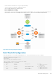

• Access switch A1 is connected to two VLT peers (Dell-1 and Dell-2).
• The two VLT peers are connected to an upstream switch R1.
• OSPF is configured in Dell-1, Dell-2, and R1 switches.
• Dell-1 is configured as the root bridge.
• Dell-1 is configured as the VLT primary.
• As the Router ID of Dell-1 is the highest in the topology (highest loopback address of 172.17.1.1), Dell-1 is the OSPF Designated Router.
• As the Router ID of Dell-2 is the second highest in the topology (172.16.1.1), Dell-2 is the OSPF Backup Designated Router.
Figure 135. Peer Routing Configuration Example
Dell-1 Switch Configuration
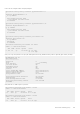
In the following output, RSTP is enabled with a bridge priority of 0. This ensures that Dell-1 becomes the root bridge.
DellEMC#1#show run | find protocol
protocol spanning-tree pvst
no disable
vlan 1,20,800,900 bridge-priority 0
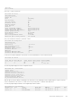
The following output shows the existing VLANs.
DellEMC#1#show vlan | find NUM
NUM Status Description Q Ports
* 1 Active U Po10 (Te 0/0-1)
U Te 0/4,47
20 Active OSPF PEERING VLAN U Po1 (Te 0/6)
V Po10 (Te 0/0-1)
800 Active Client-VLAN V Po10 (Te 0/0-1)
900 Active Client-VLAN-2 V Po10 (Te 0/0-1)
Virtual Link Trunking (VLT)
893