
Concept Guide
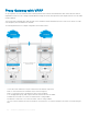

• The core routers C1 and D1 in local VLT Domain along with C2 and D2 in the remote VLT Domain are part of a Layer 3 cloud.
• The core routers C1, D1, C2, D2 are in a VRRP group with the same vrrp-group ID.
When a virtual machine running in Server Rack 1 migrates to Server Rack 2, L3 packets for that VM are routed through the default
gateway.
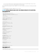
The following examples show sample congurations of the core routers.
NOTE: The following conguration assumes that all VLT-related settings are already present on the respective devices.
Sample conguration of C1:
vlt domain 10
peer-link port-channel 128
back-up destination 10.16.140.6
system-mac mac-address 00:00:aa:00:00:00
unit-id 0
peer-routing
interface port-channel 128
channel member ten 1/1/1
channel member ten 1/1/2
no shutdown
int ten 1/5/1
port-channel-protocol lacp
port-channel 10 mode active
no shut
int ten 1/4/1
port-channel-protocol lacp
port-channel 20 mode active
no shut
interface port-channel 10
vlt-peer-lag po 10
switchport
no shutdown
interface port-channel 20
vlt-peer-lag po 20
switchport
no shutdown
int vlan 100
ip address 100.1.1.1/24
tagged port-channel 10
vrrp-group 10
advertise-interval 60
virtual-ip 100.1.1.254
priority 100
no shutdown
int vlan 200
tagged port-channel 20
no shutdown
router ospf 10
network 100.1.1.0/24 area 0
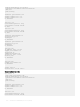
Sample conguration of D1:
vlt domain 10
peer-link port-channel 128
Virtual Router Redundancy Protocol (VRRP)
1113