
Users Guide

• The Header that gets attached to the packet is 38 bytes long. In case of a packet with L3 VLAN, it would be 42 bytes long.
The original payload /original mirrored data starts from the 39
th
byte in a given ERPM packet. The first 38/42 bytes of the
header needs to be ignored/ chopped off.
• Some tools support options to edit the capture file. We can make use of such features (for example: editcap ) and chop the
ERPM header part and save it to a new trace file. This new file (i.e. the original mirrored packet) can be converted back into
stream and fed to any egress interface.
b Using Python script
• Either have a Linux server's ethernet port ip as the ERPM destination ip or connect the ingress interface of the server to the
ERPM MirrorToPort. The analyzer should listen in the forward/egress interface. If there is only one interface, one can choose
the ingress and forward interface to be same and listen in the tx direction of the interface.
• Download/ Write a small script (for example: erpm.py) such that it will strip the given ERPM packet starting from the bit
where GRE header ends. Basically all the bits after 0x88BE need to be removed from the packet and sent out through
another interface.
• This script erpm.zip is available for download at the following location: http://en.community.dell.com/techcenter/
networking/m/force10_networking_scripts/20438882.aspx
• Unzip the erpm.zip and copy the erpm.py file to the Linux server.
• Run the python script using the following command:
python erpm.py -i <ingress interface> -o <egress interface>
erpm.py : This is the script downloaded from the script store.
<Ingress interface> : Specify the interface id which is connected to the mirroring port or this should be interface whose ip address has
been specified as the destination ip address in the ERPM session.
<Egress interface> : Specify another interface on the Linux server via which the decapsulation packets can Egress. In case there is only
one interface, the ingress interface itself can be specified as Egress and the analyzer can listen in the tx direction.
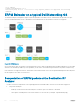
Port Monitoring on VLT
Devices on which VLT is configured are seen as a single device in the network. You can apply port monitoring function on the VLT devices
in the network.
Port monitoring enables ingress or egress traffic traversing on a port to be sent to another port so that the traffic can be analyzed. The
port to which traffic is sent for analysis is called the mirroring port. This port is connect to a port analyzer, which performs the traffic
analysis function.
Depending up on the location of the port to which the port analyzer is connected, port monitoring is classified into three categories: local
Port mirroring, remote port mirroring (RPM), and encapsulated remote port mirroring (ERPM).
NOTE
: For more information on port monitoring, see Port Monitoring.
The port monitoring or mirroring function when applied to VLT devices works as expected except with some restrictions. You can
configure RPM or ERPM monitoring between two VLT peers. As VLT devices are seen as a single device in the network, when a fail over
occurs, the source or destination port on one of the VLT peers becomes inactive causing the monitoring session to fail. As a result, Dell
Networking OS does not allow local Port mirroring based monitoring to be configured between VLT peers. However, you can create local
Port mirroring monitoring sessions separately on individual devices that are a part of the VLT configuration.
NOTE
: For more information on configuring VLT, see Configuring VLT.
VLT Non-fail over Scenario
Consider a scenario where port monitoring is configured to mirror traffic on a VLT device's port or LAG to a destination port on some
other device (TOR) on the network. When there is no fail over to the VLT peer, the VLTi link (ICL LAG) also receives the mirrored traffic
Port Monitoring
623