
Users Guide

• mstp: enables root guard on an MSTP-enabled port.
• rstp: enables root guard on an RSTP-enabled port.
• pvst: enables root guard on a PVST-enabled port.
To disable STP root guard on a port or port-channel interface, use the no spanning-tree 0 rootguard command in an interface
configuration mode.
To verify the STP root guard configuration on a port or port-channel interface, use the show spanning-tree 0 guard
[interface interface] command in a global configuration mode.
Enabling SNMP Traps for Root Elections and
Topology Changes
To enable SNMP traps individually or collectively, use the following commands.
• Enable SNMP traps for spanning tree state changes.
snmp-server enable traps stp
• Enable SNMP traps for RSTP, MSTP, and PVST+ collectively.
snmp-server enable traps xstp
Configuring Spanning Trees as Hitless
You can configure STP, RSTP, MSTP, and PVST+ to be hitless (configure all or none as hitless). When configured as hitless, critical
protocol state information is synchronized between the RPMs so that RPM failover is seamless and no topology change is triggered.
To be hitless per spanning tree type or for all spanning tree types, use the following commands.
• Configure LACP to be hitless.
CONFIGURATION mode
redundancy protocol lacp
• Configure all spanning tree types to be hitless.
CONFIGURATION mode
redundancy protocol xstp
Example of Configuring all Spanning Tree Types to be Hitless
Dell(conf)#redundancy protocol xstp
Dell#show running-config redundancy
!
redundancy protocol xstp
Dell#
STP Loop Guard
The STP loop guard feature provides protection against Layer 2 forwarding loops (STP loops) caused by a hardware failure, such as a
cable failure or an interface fault. When a cable or interface fails, a participating STP link may become unidirectional (STP requires links to
be bidirectional) and an STP port does not receive BPDUs. When an STP blocking port does not receive BPDUs, it transitions to a
Forwarding state. This condition can create a loop in the network.
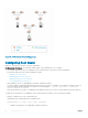
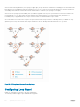
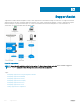
For example, in the following example (STP topology 1, upper left), Switch A is the root switch and Switch B normally transmits BPDUs to
Switch C. The link between Switch C and Switch B is in a Blocking state. However, if there is a unidirectional link failure (STP topology 1,
lower left), Switch C does not receive BPDUs from Switch B. When the max-age timer expires, the STP port on Switch C becomes
unblocked and transitions to Forwarding state. A loop is created as both Switch A and Switch C transmit traffic to Switch B.
Spanning Tree Protocol (STP)
847