
Administrator Guide
CONFIGURATION mode
delay-restore delay-restore-time
The range is from 1 to 1200.
The default is 90 seconds.
Reconfiguring the Default VLT Settings (Optional)
To reconfigure the default VLT settings, use the following commands.
1. Enter VLT-domain configuration mode for a specified VLT domain.
CONFIGURATION mode
vlt domain domain-id
The range of domain IDs is from 1 to 1000.
2. After you configure a VLT domain on each peer switch and connect (cable) the two VLT peers on each side of the VLT interconnect,
the system elects a primary and secondary VLT peer device. To configure the primary and secondary roles before the election process,
use the primary-priority command. Enter a lower value on the primary peer and a higher value on the secondary peer.
If the primary peer fails, the secondary peer (with the higher priority) takes the primary role. If the primary peer (with the lower
priority) later comes back online, it is assigned the secondary role (there is no preemption).
3. (Optional) When you create a VLT domain on a switch, Dell EMC Networking OS automatically creates a VLT-system MAC address
used for internal system operations.
VLT DOMAIN CONFIGURATION mode
system-mac mac-address mac-address
To explicitly configure the default MAC address for the domain by entering a new MAC address, use the system-mac command. The
format is aaaa.bbbb.cccc.
Also, reconfigure the same MAC address on the VLT peer switch.
Use this command to minimize the time required for the VLT system to synchronize the default MAC address of the VLT domain on
both peer switches when one peer switch reboots.
4. (Optional) When you create a VLT domain on a switch, Dell EMC Networking OS automatically assigns a unique unit ID (0 or 1) to each
peer switch.
VLT DOMAIN CONFIGURATION mode
unit-id {0 | 1}
To explicitly configure the default values on each peer switch, use the unit-id command.
Configure a different unit ID (0 or 1) on each peer switch.
Unit IDs are used for internal system operations.
Use this command to minimize the time required for the VLT system to determine the unit ID assigned to each peer switch when one
peer switch reboots.
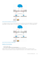
Connecting a VLT Domain to an Attached Access Device (Switch or
Server)
To connect a VLT domain to an attached access device, use the following commands.
On a VLT peer switch: To connect to an attached device, configure the same port channel ID number on each peer switch in the VLT
domain.
1. Configure the same port channel to be used to connect to an attached device and enter interface configuration mode.
CONFIGURATION mode
interface port-channel id-number
2. Remove an IP address from the interface.
INTERFACE PORT-CHANNEL mode
no ip address
3. Place the interface in Layer 2 mode.
INTERFACE PORT-CHANNEL mode
switchport
4. Add one or more port interfaces to the port channel.
INTERFACE PORT-CHANNEL mode
Virtual Link Trunking (VLT)
887