
Deployment Guide

38 Leaf-Spine Deployment and Best Practices Guide | Version 1.0
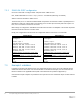
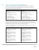
8 Example 2: Layer 3 with Dell EMC leaf and Cisco Nexus
spine switches
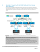
In this section, the Dell EMC Networking Z9100-ON spines used in the previous example are replaced with
Cisco Nexus 5600 series spines as shown in Figure 15. BGP and OSPF configuration examples are included.
S4048-ON leaf switch configuration is identical to that covered in Section 7.1 and is not repeated in this
section.
Note: The BGP ASNs and IP addresses defined in Section 6 are used here.
Rack 2Rack 1
S4048-Leaf4
Nexus 5600
Spine1
Nexus 5600
Spine 2
S4048-Leaf3
VLT i
S4048-Leaf2
S4048-Leaf1
VLT i
Server 2
Server 1
L3 Connection
L2 Connection
ECMP
Eth 2/1-2/4
Fo 1/53-54Fo 1/53-54
Te 1/4Te 1/4
Te 1/48
Te 1/48
Po 1
Po 1
Eth 2/1-2/4
All leaf switch uplinks
Fo 1/49 - Fo 1/50
IP Address 10.60.1.7/24
Gateway 10.60.1.1
Leaf 3
VLAN 60:
10.60.1.1/24
Leaf 4
VLAN 60:
10.60.1.2/24
IP Address 172.16.1.7/24
Gateway 172.16.1.1
Leaf 1
VLAN 50:
172.16.1.1/24
Leaf 2
VLAN 50:
172.16.1.2/24
Example 2: Layer 3 leaf-spine topology with Dell EMC leaf and Cisco Nexus spine switches
Note: All switch configuration files for the topology in Figure 15 are contained in the attachment named
Example2_config_files.pdf. The files may be edited as needed in a plain text editor and commands pasted
directly into switch consoles.
Dell EMC Networking switches start at their factory default settings per Appendix A.
Cisco Nexus switches in this example were reset to their factory default configurations by running write
erase followed by reload. After reload, "Power on Auto Provisioning" was not used, the admin password
was configured and the Nexus “basic configuration dialog” was not used. Refer to your Nexus system
documentation for more information.