
White Papers


Stacking and VLT
Dell EMC Technical White Paper
3 Overview of Virtual Link Trunking (VLT)
VLT aggregates two identical physical switches to form a single logical extended switch. This single logical
entity ensures high availability and high resilience for all its connected core switches, and clients. Even though
both the switches form together as a single logical unit, the control and data plan of both switches remain
discrete. As a result, we can apply a switch firmware upgrade without bringing down the network.
As high availability has become mandatory in modern data centers and enterprise networks, VLT plays a vital
role connecting to all its access nodes with seamless traffic flow, efficient load balancing, and a loop-free
mechanism.
3.1 VLT architecture
The VLT fabric consists of two nodes that provide a logical single switch view to the connected devices.
However, each of the VLT peers has its own control and data planes and can be configured individually for port,
protocol, and management behaviors.
The VLT application elects the primary node that is based on the lower MAC address. However, with the
primary-priority command, the node with the least primary priority becomes the primary node. This election is
not preempted, which means whenever there is a change in priority, the primary role does not change until the
nodes are rebooted or the VLT process is restarted.
VLT-related information is shared between nodes through the specific reserved VLAN (VLAN 4094). The VLT
database (VLT DB) is used to store the VLT control information to be exchanged between the VLT nodes. The
local database (local DB) stores the MAC and ARP table entries.
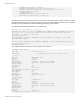
Figure 2: Virtual Link Trunking