
White Papers


Stacking and VLT
Dell EMC Technical White Paper
3.5 Link failover scenarios in VLT
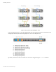
As shown in Figure 3, when the upstream layer-3 link 1 fails, the traffic is forced to take the alternate ECMP
path to the VLT domain through link 2 to reach its destination.
Figure 3: Link failure in upstream layer 3 link
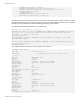
In this scenario, where the link 3 in the VLT port channel fails as shown in Figure 4, the traffic will then pass
through the VLTi and then take the link 4 as the MAC learned on the failed VLT is now mapped to the VLTi port.
Figure 4: Traffic flow during link failure in the VLT port channel