Dell EMC VEP4600 Installation Guide Abstract This document provides the steps for installing the Dell EMC VEP4600 networking switch. It includes platform description, configuration, and site installation. Dell Solutions April 2021 Rev.
Notes, cautions, and warnings NOTE: A NOTE indicates important information that helps you make better use of your product. CAUTION: A CAUTION indicates either potential damage to hardware or loss of data and tells you how to avoid the problem. WARNING: A WARNING indicates a potential for property damage, personal injury, or death. © 2016 - 2020 Dell Inc. or its subsidiaries. All rights reserved. Dell, EMC, and other trademarks are trademarks of Dell Inc. or its subsidiaries.
Contents Chapter 1: About this guide........................................................................................................... 5 Related documents............................................................................................................................................................. 5 Information symbols............................................................................................................................................................
Fan module installation.....................................................................................................................................................29 Fan module replacement........................................................................................................................................... 30 Chapter 7: Management ports......................................................................................................31 RS-232 console port access..............
1 About this guide This guide provides site preparation recommendations, step-by-step procedures for rack mounting and desk mounting your platform, inserting modules, and connecting to a power source. CAUTION: To avoid electrostatic discharge (ESD) damage, wear grounding wrist straps when handling this equipment. NOTE: Only trained and qualified personnel can install this equipment. Read this guide before you install and power up this equipment. This equipment contains two power cords.
Information symbols This book uses the following information symbols: NOTE: The Note icon signals important operational information. CAUTION: The Caution icon signals information about situations that could result in equipment damage or loss of data. NOTE: The Warning icon signals information about hardware handling that could result in injury. NOTE: The ESD Warning icon requires that you take electrostatic precautions when handling the device.
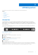
2 VEP4600 platform The following sections describe the Dell EMC Virtual Edge Platform 4600 (VEP4600) platform: Topics: • • • • • • • Introduction Features Physical dimensions LED display Pre-requisites VEP4600 configurations Luggage tag Introduction The VEP4600 platform is a one rack unit, x86-based networking platform running virtualized universal customer premise equipment (uCPE) functions and basic switching/routing functions as a top-of-rack device.
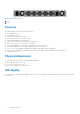
Figure 3. VEP4600 PSU-side 1. PSUs 2.
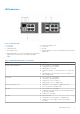
LED behaviors Figure 4. VEP4600 LEDs 1. 3. 5. 7. Power LED System LED Temperature LED SFP+ indicator LED 2. 4. 6. 8. Primary unit indicator LED Locator LED Fan LED 10/100/1000 BaseT RJ-45 networking link (left) and activity (right) LEDs 9. 10/100/1000 BaseT RJ-45 networking link (left) and activity (right) LEDs for the processor (left) and for the BMC (right) Table 1.
Table 1.
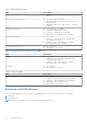
Figure 5. rNDC front panel LED call-outs Table 4. Expansion card LEDs LED Description 1.) System LED ● ● ● ● ● Off—Card is off Solid green—Normal operation Solid yellow—Citical card error Flashing green—Booting Flashing yellow—Noncritical card error 2.
VEP4600 configurations You can order the VEP4600 in the following configuration: ● Two 10GbE SFP+ and four 1000 Base-T ports, one or two AC PSU power supplies, and four or five normal fan subsystems with airflow from the front to back, depending on the configuration. NOTE: DC PSU optional configuration offered as a custom-kit. Simply contact a Dell Sales Representative. ○ Sixteen-core systems use five fans and two AC PSUs. ○ Eight-core systems use four fans one or two AC PSUs.
3 Site preparations VEP4600 is universal customer premise equipment (uCPE). To connect the service provider edge or enterprise branch to the cloud, use VEP4600 to host multiple virtual network functions (VNFs), such as SD-WAN, routing, firewall, and deep-packet inspection. For more information about platform specifications, see Specifications . NOTE: Install the VEP4600 in a rack or cabinet before installing the components.
The cabinet must meet minimum size requirements. Airflow must be in accordance with the Electronic Industries Alliance (EIA) standard. Ensure that there is a minimum of 5 inches (12.7 cm) between the intake and exhaust vents and the cabinet wall. Rack mounting When you prepare your equipment rack, ensure that the rack is grounded. Ground the equipment rack to the same ground point the power service in your area uses. The ground path must be permanent.
● Short push: ○ Sends ACPI power event to the Operating System (OS.) NOTE: Response depends on configuration of how the OS is booted-up when it receives a ACPI power event. The response may ignore the button push or shutdown the system. ● Long push: ○ Sends ACPI power event to the OS and immediately puts the CPU to sleep. When CPU is in sleep state, a short push brings the CPU out of sleep and reboots the system. CAUTION: Always turn off the processor correctly.
4 VEP4600 installation To install the VEP4600, complete the installation procedures in the order presented in this section. Always handle the platform and components with care. Avoid dropping the platform or its field replaceable units (FRUs). NOTE: ESD damage can occur if components are mishandled. Always wear an ESD-preventive wrist or heel ground strap when handling the VEP4600 and components.
CAUTION: Professional installation instructions: This product is designed for specific applications and needs to be installed by qualified personnel with RF and regulatory related knowledge. The general user shall not attempt to install or change the setting. Ground lug Dell EMC recommends you ground your switch; however, grounding is optional and the ground lug assembly kit is not included with the switch. The ground lug must be a UL-recognized, crimp-type lug.
Rack or cabinet hardware installation You may either place the platform on a rack shelf or mount the platform directly into a 19" wide, EIA-310- E-compliant rack. The platform includes two-post rail assemblies. WARNING: This document is a condensed reference. Read the safety instructions in your Safety, Environmental, and Regulatory information booklet before you begin. NOTE: The illustrations in this document are not intended to represent a specific platform.
Figure 9. Reverse small bracket Figure 10. Reversed rail mounting bracket position 3. Mount unit on front-mount (flush-mount) rails. Figure 11. Platform flush-mounted on two posts Two-post installation To easily configure your rack for installation of the VEP4600, use the two-post rack mounting system provided. To complete this installation, supply four rack-mounting screws. To begin installation, separate each rail assembly by sliding the inside rail out of the outside rail.
Figure 12. Two-post rail Four-post installation To complete this installation, supply eight rack-mounting screws. NOTE: For more installation instructions, see the installation labels attached to the rail assembly. 1. Separate each rail assembly by sliding the inside rail out of the outside rail. 2. Attach the inner platform rails to the VEP4600. Line up the half-holes on the rail with the mounting heads on the platform and attach the rail to the platform. Slide the rail back until it locks into place.
Figure 14. Platform four-post front installed 5. Align the rear rack rails to the front rail and slide into place. Figure 15. Rear platform rail About three inches before you fully insert your platform, the rail locking feature engages to keep the platform from inadvertently sliding out and falling. NOTE: Screw the rear rails into rear rack posts to secure them. Figure 16. Platform four-post rear installed To remove the platform, unscrew the rack-mounting screws and slide the platform forward.
WARNING: When working with optical fibers, follow all warning labels and always wear eye protection. Never look directly into the end of a terminated or unterminated fiber or connector as it may cause eye damage. 1. Position the optic to enter the port correctly. The optic has a key that prevents it from being inserted incorrectly. 2. Insert the optic into the port until it gently snaps into place.
5 Power supplies VEP4600 power supply specifications, installation, and replacement. The VEP4600 ships with one or two AC power supplies, depending on the configuration. Airflow is from the front to back. The red indicator is the normal airflow direction. NOTE: DC PSU optional configuration offered as a custom-kit. Contact Dell EMC support site at www.dell.com/support/. Two PSUs are required for full redundancy, but the platform can operate with a single PSU.
DC PSU LEDs 1. ● ● ● DC PSUs Solid green—Input voltage ok and output good. Flashing yellow (amber)—There is a Standby mode or PSU failure (OC, OT, OV, Fan fault). Off—PSU is off. AC power supply installation NOTE: The PSU slides into the slot smoothly. Do not force a PSU into a slot as this action may damage the PSU or the platform. NOTE: Ensure that you correctly install the PSU. When you install the PSU correctly, the power connector is on the left side of the PSU.
AC power supply replacement CAUTION: Disconnect the power cord before removing the power supplies. Also, disconnect all power cords before servicing. NOTE: The PSU slides into the slot smoothly. Do not force a PSU into a slot as this action may damage the PSU or the VEP4600. NOTE: If a PSU fails, you must replace the PSU unit. There are no field serviceable components in the PSU. To request a hardware replacement, see https://www.dell.com/support .
Figure 18. Molex terminal block 7. Tighten the screws with a number 1 Philips screwdriver on the terminal block to secure the number 10 to number 3 AWG wires. Figure 19. Tighten wires to terminal block 8. Mate the terminal block to the connector on DC PSU. Place the VEP4600 System Label from the kit on top of the DC PSU cover.
Figure 20. Mate terminal block to DC PSU 9. Locate the overlay label in the kit and place it over the existing label in the unit. Figure 21. DC overlay label 10. Insert DC PSUs to switch. Figure 22. Insert DC PSU to switch 11. Crimp number 6 and number 3 AWG wire to ground lug.
Figure 23. Ground lug 12. Attach ground wire to switch. Secure ground lug with a number 1 Philips screwdriver. Figure 24. Attach ground lug and wire to switch NOTE: Torque screws to 6-inch pounds. Figure 25.
6 Fans The VEP4600 comes from the factory with one or two PSUs and four or five fan modules installed in the platform, depending on the configuration. The fan modules and the power supplies, which have integrated fans, are hot-swappable. In addition to the power supply modules, you can order fan modules separately to install. The VEP4600 supports airflow from the I/O side to the PSU side. The red indicator is the normal airflow direction.
1. Fan module installation Fan module replacement To request a hardware replacement, see https://www.dell.com/support. CAUTION: Complete the following steps within one minute or the platform temperature could rise above safe thresholds and the platform could shut down: 1. Squeeze the two orange levers on the fan module together to unlock the module. With the two orange levers squeezed, pull and slide the fan module out of the bay. 2. Slide the replacement module into the bay.
7 Management ports Besides the 10/100/1000Base-T RJ-45 ports, the VEP4600 provides several ports for management and storage. NOTE: The output examples in this section are for reference only. Your output may vary. Topics: • • RS-232 console port access MicroUSB-B console port access RS-232 console port access The RS-232 console port is on the I/O-side of the VEP4600. Figure 27. VEP4600 RS-232 console and management ports 1.
MicroUSB-B console port access The MicroUSB-B console port is on the front below the two USB ports on the VEP4600. The terminal settings are the same for the serial console port and the RS-232/RJ-45 console port: ● ● ● ● ● 115200 baud rate No parity 8 data bits 1 stop bit No flow control When you connect the microUSB-B port, it becomes the primary connection and, while connected, all messages are sent to the microUSB-B port. NOTE: The VEP4600 uses the Silicon Labs CP2102 USB-B chip.
8 Specifications This section lists the VEP4600 specifications. CAUTION: Operate the product at an ambient temperature not higher than 113°F (45°C). NOTE: For RoHS information, see Restricted Material Compliance . Topics: • • • • • Chassis physical design IEEE standards Safety standards and compliance agency certifications Product recycling and disposal Agency compliance Chassis physical design Table 6. Chassis physical design Parameter Specifications Height 1.72 inches (43.6 mm) Width 17.
Table 8. AC power requirements Parameter Specifications AC power supply 100–240 VAC 50/60 Hz Typical current draw per platform ● 110VAC: 1.89A (16 core) 240VAC: 0.86 A (16 core) ● 110VAC: 1.5A (8 core ) 240VAC: 0.7A (8 core) ● 110VAC: 1.35A (4 core) 240VAC: 0.65A (4 core) Maximum power capability ● 5-fan 16-core processor: 311W ● 4-fan 8-core processor: 230W ● 4-fan 4-core processor: 220W Typical power consumption ● 5-fan 16-core processor: 206.
Waste electrical and electronic equipment (WEEE) directive for recovery, recycle and reuse of IT and telecommunications products Dell EMC platforms are labeled in accordance with European Directive 2002/96/EC concerning waste electrical and electronic equipment (WEEE). The Directive determines the framework for the return and recycling of used appliances as applicable throughout the European Union.
This transmitter must not be co-located or operating in conjunction with any other antenna or transmitter. Radiation Exposure Statement: This equipment complies with FCC radiation exposure limits set forth for an uncontrolled environment. This equipment should be installed and operated with minimum distance 20cm between the radiator & your body. Industry Canada Statement This device complies with Industry Canada license-exempt RSS standard(s). Operation is subject to the following two conditions: 1.
Japan VCCI compliance for class A equipment Figure 29. Japan: VCCI compliance for class A equipment This is Class A product based on the standard of the Voluntary Control Council For Interference by Information Technology Equipment (VCCI). If this equipment is used in a domestic environment, radio disturbance may arise. When such trouble occurs, the user may be required to take corrective actions. NOTE: Use the AC power cords with Dell EMC equipment only.
Mexico certification of compliance La operación de este equipo está sujeta a las siguientes dos condiciones: 1. Es posible que este equipo o dispositivo no cause interferencia perjudicial y 2. Este equipo o dispositivo debe aceptar cualquier interferencia, incluyendo la que pueda causar su operación no deseada.
Thailand radio compliance certificate translated Singapore certification of compliance Singapore radio compliance.
9 Dell EMC support The Dell EMC support site provides documents and tools to help you effectively use Dell EMC equipment and mitigate network outages. Through the support site you can obtain technical information, access software upgrades and patches, download available management software, and manage your open cases. The Dell EMC support site provides integrated, secure access to these services. To access the Dell EMC support site, go to www.dell.com/support/.