Dell EMC VEP4600 Installation Guide Abstract This document provides the steps for installing the Dell EMC VEP4600 networking switch. It includes platform description, configuration, and site installation. Dell Solutions July 2020 Rev.
Notes, cautions, and warnings NOTE: A NOTE indicates important information that helps you make better use of your product. CAUTION: A CAUTION indicates either potential damage to hardware or loss of data and tells you how to avoid the problem. WARNING: A WARNING indicates a potential for property damage, personal injury, or death. © 2016 - 2020 Dell Inc. or its subsidiaries. All rights reserved. Dell, EMC, and other trademarks are trademarks of Dell Inc. or its subsidiaries.
Contents Chapter 1: About this guide..............................................................................................................5 Related documents............................................................................................................................................................... 5 Information symbols..............................................................................................................................................................
Components.........................................................................................................................................................................30 Fan module installation........................................................................................................................................................30 Fan module replacement..................................................................................................................................
1 About this guide This guide provides site preparation recommendations, step-by-step procedures for rack mounting and desk mounting your platform, inserting modules, and connecting to a power source. CAUTION: To avoid electrostatic discharge (ESD) damage, wear grounding wrist straps when handling this equipment. NOTE: Only trained and qualified personnel can install this equipment. Read this guide before you install and power up this equipment. This equipment contains two power cords.
CAUTION: The Caution icon signals information about situations that could result in equipment damage or loss of data. NOTE: The Warning icon signals information about hardware handling that could result in injury. NOTE: The ESD Warning icon requires that you take electrostatic precautions when handling the device.
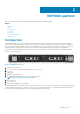
2 VEP4600 platform The following sections describe the Dell EMC Virtual Edge Platform 4600 (VEP4600) platform: Topics: • • • • • • • Introduction Features Physical dimensions LED display Pre-requisites VEP4600 configurations Luggage tag Introduction The VEP4600 platform is a one rack unit, x86-based networking platform running virtualized universal customer premise equipment (uCPE) functions and basic switching/routing functions as a top-of-rack device.
Figure 3. VEP4600 PSU-side 1. PSUs 2.
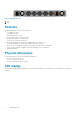
LED behaviors Figure 4. VEP4600 LEDs 1. 3. 5. 7. Power LED System LED Temperature LED SFP+ indicator LED 2. 4. 6. 8. Master LED Locator LED Fan LED 10/100/1000 BaseT RJ-45 networking link (left) and activity (right) LEDs 9. 10/100/1000 BaseT RJ-45 networking link (left) and activity (right) LEDs for the processor (left) and for the BMC (right) Table 1.
Table 1.
Figure 5. rNDC front panel LED call-outs Table 4.
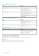
VEP4600 configurations You can order the VEP4600 in the following configuration: • Two 10GbE SFP+ and four 1000 Base-T ports, one or two AC PSU power supplies, and four or five normal fan subsystems with airflow from the front to back, depending on the configuration. NOTE: DC PSU optional configuration offered as a custom-kit. Simply contact a Dell Sales Representative. ○ Sixteen-core systems use five fans and two AC PSUs. ○ Eight-core systems use four fans one or two AC PSUs.
3 Site preparations VEP4600 is universal customer premise equipment (uCPE). To connect the service provider edge or enterprise branch to the cloud, use VEP4600 to host multiple virtual network functions (VNFs), such as SD-WAN, routing, firewall, and deep-packet inspection. For more information about platform specifications, see Specifications . NOTE: Install the VEP4600 in a rack or cabinet before installing the components.
Platform ground Dell EMC recommends you ground your platform. Use the VEP4600 in a common bond network (CBN). Connect the grounding cables as described in the VEP4600 installation section. . Fans and airflow The VEP4600 supports fan units with airflow from front to back. Fan combinations The fan speed varies based on internal temperature monitoring. The VEP4600 never intentionally turns off the fans. Table 5.
Storing components If you do not install your VEP4600 and components immediately, properly store the platform and all optional components using these guidelines: • • • Storage location temperature must remain constant. The storage range is from -40°C to 70°C (-40°F to 158°F). Store on a dry surface or floor, away from direct sunlight, heat, and air conditioning ducts. Store in a dust-free environment. NOTE: ESD damage can occur when components are mishandled.
4 VEP4600 installation To install the VEP4600, complete the installation procedures in the order presented in this section. Always handle the platform and components with care. Avoid dropping the platform or its field replaceable units (FRUs). NOTE: ESD damage can occur if components are mishandled. Always wear an ESD-preventive wrist or heel ground strap when handling the VEP4600 and components.
Ground lug Dell EMC recommends you ground your switch; however, grounding is optional and the ground lug assembly kit is not included with the switch. The ground lug must be a UL-recognized, crimp-type lug. To order a UL-certified ground lug with bracket, contact your Dell EMC sales representative. NOTE: The ground cable is not included with the switch.
NOTE: The illustrations in this document are not intended to represent a specific platform. NOTE: Do not the use the mounted two-post rails as a shelf or a workplace. Rack mount safety considerations • • • • • • Rack loading—Overloading or uneven loading of racks may result in shelf or rack failure, possibly damaging the equipment and causing personal injury. Stabilize racks in a permanent location before loading begins. Mount the components starting at the bottom of the rack, then work to the top.
Figure 9. Platfrom rail attachment 2. Repeat on the other side of the platform. 3. Attach the outer platform rails to the two-post rack rails using two user-supplied screws on each side. 4. After you install both rails, line up the platform rails with the installed rack rails. Slide the platform in until it is flush with the middle of rack. About three inches before you fully insert your platform, the rail locking feature engages to keep the platform from inadvertently sliding out and falling. Figure 10.
Figure 11. Remove 8x M3 2. Reverse the small bracket. Secure bracket with 8X M3 screws. Torque to 3 In/lbs. Figure 12. Reverse small bracket Figure 13. Reversed rail mounting bracket position 3. Mount unit on front-mount (flush-mount) rails.
Figure 14. Platform flush-mounted on two posts Four-post installation To complete this installation, supply eight rack-mounting screws. NOTE: For more installation instructions, see the installation labels attached to the rail assembly. 1. Separate each rail assembly by sliding the inside rail out of the outside rail. 2. Attach the inner platform rails to the VEP4600. Line up the half-holes on the rail with the mounting heads on the platform and attach the rail to the platform.
Figure 16. Platform four-post front installed 5. Align the rear rack rails to the front rail and slide into place. Figure 17. Rear platform rail About three inches before you fully insert your platform, the rail locking feature engages to keep the platform from inadvertently sliding out and falling. NOTE: Screw the rear rails into rear rack posts to secure them. Figure 18. Platform four-post rear installed To remove the platform, unscrew the rack-mounting screws and slide the platform forward.
WARNING: When working with optical fibers, follow all warning labels and always wear eye protection. Never look directly into the end of a terminated or unterminated fiber or connector as it may cause eye damage. 1. Position the optic to enter the port correctly. The optic has a key that prevents it from being inserted incorrectly. 2. Insert the optic into the port until it gently snaps into place.
5 Power supplies VEP4600 power supply specifications, installation, and replacement. The VEP4600 ships with one or two AC power supplies, depending on the configuration. Airflow is from the front to back. The red indicator is the normal airflow direction. NOTE: DC PSU optional configuration offered as a custom-kit. Contact Dell EMC support site at www.dell.com/ support/. Two PSUs are required for full redundancy, but the platform can operate with a single PSU.
DC PSU LEDs Figure 20. Installed DC PSU(s) 1. DC PSUs • • • Solid green—Input voltage ok and output good. Flashing yellow (amber)—There is a Standby mode or PSU failure (OC, OT, OV, Fan fault). Off—PSU is off. AC power supply installation NOTE: The PSU slides into the slot smoothly. Do not force a PSU into a slot as this action may damage the PSU or the platform. NOTE: Ensure that you correctly install the PSU. When you install the PSU correctly, the power connector is on the left side of the PSU.
AC power supply replacement CAUTION: Disconnect the power cord before removing the power supplies. Also, disconnect all power cords before servicing. NOTE: The PSU slides into the slot smoothly. Do not force a PSU into a slot as this action may damage the PSU or the VEP4600. NOTE: If a PSU fails, you must replace the PSU unit. There are no field serviceable components in the PSU. To request a hardware replacement, see https://www.dell.com/support .
7. Tighten the screws with a number 1 Philips screwdriver on the terminal block to secure the number 10 to number 3 AWG wires. Figure 23. Tighten wires to terminal block 8. Mate the terminal block to the connector on DC PSU. Place the VEP4600 System Label from the kit on top of the DC PSU cover. Figure 24. Mate terminal block to DC PSU 9. Locate the overlay label in the kit and place it over the existing label in the unit. Figure 25. DC overlay label 10. Insert DC PSUs to switch.
Figure 26. Insert DC PSU to switch 11. Crimp number 6 and number 3 AWG wire to ground lug. Figure 27. Ground lug 12. Attach ground wire to switch. Secure ground lug with a number 1 Philips screwdriver. Figure 28.
NOTE: Torque screws to 6-inch pounds. Figure 29.
6 Fans The VEP4600 comes from the factory with one or two PSUs and four or five fan modules installed in the platform, depending on the configuration. The fan modules and the power supplies, which have integrated fans, are hot-swappable. In addition to the power supply modules, you can order fan modules separately to install. The VEP4600 supports airflow from the I/O side to the PSU side. The red indicator is the normal airflow direction.
Figure 31. VEP4600 fan module installation a. Fan module installation Fan module replacement To request a hardware replacement, see https://www.dell.com/support. CAUTION: Complete the following steps within one minute or the platform temperature could rise above safe thresholds and the platform could shut down: 1. Squeeze the two orange levers on the fan module together to unlock the module. With the two orange levers squeezed, pull and slide the fan module out of the bay. 2.
7 Management ports Besides the 10/100/1000Base-T RJ-45 ports, the VEP4600 provides several ports for management and storage. NOTE: The output examples in this section are for reference only. Your output may vary. Topics: • • RS-232 console port access MicroUSB-B console port access RS-232 console port access The RS-232 console port is on the I/O-side of the VEP4600. Figure 32. VEP4600 RS-232 console and management ports 1.
2. Install the DB-9 female-side of the provided copper cable into your PC’s serial port. Or install the DB-9 cable into other data terminal equipment (DTE) server hardware. 3. Keep the default terminal settings on the console as follows: • • • • • 115200 baud rate No parity 8 data bits 1 stop bit No flow control MicroUSB-B console port access The MicroUSB-B console port is on the PSU side of the VEP4600.
8 Specifications This section lists the VEP4600 specifications. CAUTION: Operate the product at an ambient temperature not higher than 113°F (45°C). NOTE: For RoHS information, see Restricted Material Compliance . Topics: • • • • • Chassis physical design IEEE standards Safety standards and compliance agency certifications Product recycling and disposal Agency compliance Chassis physical design Table 6. Chassis physical design Parameter Specifications Height 1.72 inches (43.6 mm) Width 17.
Table 8. AC power requirements Parameter Specifications AC power supply 100–240 VAC 50/60 Hz Typical current draw per platform • • • 110VAC: 1.89A (16 core) 240VAC: 0.86 A (16 core) 110VAC: 1.5A (8 core ) 240VAC: 0.7A (8 core) 110VAC: 1.35A (4 core) 240VAC: 0.65A (4 core) Maximum power capability • • • 5-fan 16-core processor: 311W 4-fan 8-core processor: 230W 4-fan 4-core processor: 220W Typical power consumption • • • 5-fan 16-core processor: 206.
Waste electrical and electronic equipment (WEEE) directive for recovery, recycle and reuse of IT and telecommunications products Dell EMC platforms are labeled in accordance with European Directive 2002/96/EC concerning waste electrical and electronic equipment (WEEE). The Directive determines the framework for the return and recycling of used appliances as applicable throughout the European Union.
FCC Caution: Any changes or modifications not expressly approved by the party responsible for compliance could void the user's authority to operate this equipment. This transmitter must not be co-located or operating in conjunction with any other antenna or transmitter. Radiation Exposure Statement: This equipment complies with FCC radiation exposure limits set forth for an uncontrolled environment. This equipment should be installed and operated with minimum distance 20cm between the radiator & your body.
2. De plus, les utilisateurs devraient aussi être avisés que les utilisateurs de radars de haute puissance sont désignés utilisateurs principaux (c.-à-d., qu’ils ont la priorité) pour les bandes 5250-5350 MHz et 5650-5850 MHz et que ces radars pourraient causer du brouillage et/ou des dommages aux dispositifs LAN-EL.
Email: EMEA Central Sales Japan VCCI compliance for Class A equipment この装置は、情報処理装置等電波障害自主規制協議会 (VCCI) の基準に基づくクラス A 情報技術装置です。 この装置を家庭環境で使用すると電波妨害を引き起こすことがあります。 この場合には使用者が適切な対策を講ずるよう要求されることがあります。 This is Class A product based on the standard of the Voluntary Control Council For Interference by Information Technology Equipment (VCCI). If this equipment is used in a domestic environment, radio disturbance may arise. When such trouble occurs, the user may be required to take corrective actions.
Radio compliance certificate Korea (Korean warning statement is only required for devices contain 2400~2483 and/or 5725~5825 MHz radios). The following is the Korean radio compliance certification: 해당 무선설비는 운용 중 전파혼신 가능성이 있음 Mexico certification of compliance La operación de este equipo está sujeta a las siguientes dos condiciones: 1. Es posible que este equipo o dispositivo no cause interferencia perjudicial y 2.
Thailand radio compliance certificate translated Singapore certification of compliance Singapore radio compliance.
9 Dell EMC support The Dell EMC support site provides documents and tools to help you effectively use Dell EMC equipment and mitigate network outages. Through the support site you can obtain technical information, access software upgrades and patches, download available management software, and manage your open cases. The Dell EMC support site provides integrated, secure access to these services. To access the Dell EMC support site, go to www.dell.com/support/.