uCPE Networking DIAG OS Guide April 2020
Notes, cautions, and warnings NOTE: A NOTE indicates important information that helps you make better use of your product. CAUTION: A CAUTION indicates either potential damage to hardware or loss of data and tells you how to avoid the problem. WARNING: A WARNING indicates a potential for property damage, personal injury, or death. © 2018 - 2019 Dell Inc. or its subsidiaries. All rights reserved. Dell, EMC, and other trademarks are trademarks of Dell Inc. or its subsidiaries.
Contents 1 About this guide........................................................................................................................... 4 Notices.................................................................................................................................................................................... 4 Related documents........................................................................................................................................................
1 About this guide Notices CAUTION: To avoid electrostatic discharge (ESD) damage, wear grounding wrist straps when handling this equipment. NOTE: Only trained and qualified personnel can install this equipment. Read this guide before you install and power up this equipment. This equipment contains two power cords. Disconnect both power cords before servicing. NOTE: This equipment contains optical transceivers, which comply with the limits of Class 1 laser radiation. Figure 1.
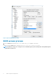
2 BIOS setup and configuration This section describes how to access the BIOS setup and configuration screen on your system. Access the BIOS setup and configuration screen from the command prompt. Ensure that your TFTP server is reachable over your network. NOTE: The following output examples are for reference only; your output may vary. NOTE: The management port IP, FTP server IP address, MAC address, and user-id shown are for illustration purpose only. Use your system’s applicable values.
Figure 2. puTTY 115200 baud rate setup BIOS access process 1. Press the delete button after the POST Lower DRAM Memory test appears on the screen. Continue pressing the delete button to progress to the BIOS setup and configuration screen. NOTE: If the BIOS setup and configuration screen window passes, power off and power on the platform again to restart the boot up process.
Figure 3. Initial boot up screen Figure 4.
Figure 5.
3 Dell EMC DIAG OS The following describes the Dell EMC diagnostics operating system (DIAG OS). Topics: • View DIAG versions View DIAG versions To display the DIAG version installed in the DIAG OS, use the dpkg -l | grep dn-diags command at the root@dell-diagos:~ prompt. root@dell-diag-os:/# dpkg -l | grep dn-diags ii dn-diags--on.deb 1.
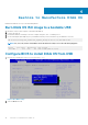
4 Restore to Manufacture DIAG OS Manufacture DIAG OS recovery for the VEP4600 platform. Burn DIAG OS ISO image to a bootable USB 1. 2. 3. 4. Mount the USB to a Linux computer or VEP4600 with DIAG OS. Log in to the Linux OS. Download the DIAG OS ISO image to the Linux computer using TCP, SCP, or a similar protocol. Use the following DD (data duplicator) CLI (command line interface) Linux command to copy the DIAG OS to the USB. dd if=onie-recovery-x86_64-dellemc_vep4600_d21xyt-r0.48.
Figure 7. Boot menu tab 3. Select UEFI: then USB Device: to boot the DIAG OS from a USB drive. Figure 8. DIAG OS USB to boot UEFI Figure 9. DIAG OS USB to boot USB device 4. Verify that Boot Option #1 lists the DIAG OS USB as the boot option. Figure 10. Boot Option #1 5. Press F4 to save and exit the utility and to start the installation.
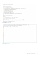
DIAG OS installation failure and resolution ESXi may create a different disk partition that is not compatible with the DIAG OS. This causes the DIAG OS installation to fail and display this error message: ONIE: Rescue Mode ... Platform : x86_64-dellemc_vep4600_d21xyt-r0 Version : x.xx.x.xx-x Build Date: 2018-04-24T03:20-0700 ▒[ 13.793445] ata4.00: failed to set xfermode (err_mask=0x40) Info: Mounting kernel filesystems... done. Info: Using eth0 MAC address: d8:9e:f3:bc:6a:a0 Info: eth0: Checking link... up.
2. Type the following then click Enter. gdisk /dev/sdc ** Rescue Mode Enabled ** ONIE-RECOVERY:/ # gdisk /dev/sdc GPT fdisk (gdisk) version 0.8.8 Partition table scan: MBR: protective BSD: not present APM: not present GPT: present Found valid GPT with protective MBR; using GPT. 3. Type o to delete the partition. Command (? for help): Command (? for help): o This option deletes all partitions and creates a new protective MBR.
other utilities. Creating new GPT entries. GPT data structures destroyed! You may now partition the disk using fdisk or other utilities. Creating new GPT entries. The operation has completed successfully. The operation has completed successfully. mkfs.fat 3.0.26 (2014-03-07) create_grub_boot_partition finished ! Creating new diag-os partition /dev/sdc2 ... Warning: The kernel is still using the old partition table. The new table will be used at the next reboot. The operation has completed successfully.
Figure 12. Save & exit After you save the changes the log in command prompt displays. Figure 13. Log in command prompt 5. Type to log in. root/calvin DIAG OS Verification NOTE: The system shows the current version. After DIAG OS installation, to verify the DIAG OS version, boot into boot into the DIAG OS by the following commands. 1. Log in into the DIAG OS using root as the username and calvinas the password. 2. Enter the sh_ver command. root@dellemc-diag-os:~#sh_ver Diag OS version VEP4600_DIAG_OS_x.xx.
5 Dell EMC DIAG OS tools This section describes how to use the Dell EMC diagnostics operating system (DIAG OS). The DIAG OS provides a suite of tools to help diagnose issues seen on the system, or to run a health check to ensure that the hardware is operating properly. Diagnostic tools The DIAG OS uses standard Linux drivers and contains the following tools you can use to evaluate the health of your system.
Syntax: edatool
+ Checking PCI 00:17.0, ID=1f228086 ....................... + Checking PCI 00:18.0, ID=1f328086 ....................... + Checking PCI 00:1f.0, ID=1f388086 ....................... + Checking PCI 00:1f.3, ID=1f3c8086 ....................... + Checking PCI 01:00.0, ID=837514e4 ....................... + Checking PCI 01:00.1, ID=837514e4 ....................... PCI devices: Overall test results --------------------- >>> Testing I2C devices: Checking I2C devices on bus 0: + Checking Clock GEN 0x69 .....
+ Checking SFP+ 22 0x50 ..... Passed + Checking SFP+ 23 0x50 ..... Passed + Checking SFP+ 24 0x50 ..... Passed + Checking SFP+ 25 0x50 ..... Passed + Checking SFP+ 26 0x50 ..... Passed + Checking SFP+ 27 0x50 ..... Passed + Checking SFP+ 28 0x50 ..... Passed + Checking SFP+ 29 0x50 ..... Passed + Checking SFP+ 30 0x50 ..... Passed + Checking SFP+ 31 0x50 ..... Passed + Checking SFP+ 32 0x50 ..... Passed + Checking SFP+ 33 0x50 ..... Passed + Checking SFP+ 34 0x50 .....
CLI options root@dellemc-diag-os:~# cputool DellEmc Diag - Cpu Tool version 1.1, x.xx.x.
Read the specified regiser in LPC bus:= cputool --readlpc --reg= --size= cputool -d -R -Z Write the specified regiser in LPC bus:= cputool --writelpc --reg= --val= --size= cputool -W -R -V -Z Usage:= -h, --h Show the help text -i, --cpuid CPU-Id -x, --x86info x86 info -r, --readmsr Read operation -w, --writemsr Write operation -n, --cpu= CPU -R, --reg= Register -V, --val= Value to be set -Z, --size= Size -d, --readlpc Read from LPC bus -W, --wri
Board Part Number : 0GRTNKA02 root@dellemc-diag-os:~# a. The test option in EEPROM devices allows you to verify the MAC address. Use this test for MAC address consistency. CLI options DellEmc Diag - Eeprom Tool version 1.5, x.xx.x.
0x22 Part Number 0x23 Serial Number 0x24 Base MAC Address 0x25 Manufacture Date 0x26 Device Version 0x27 Label Revision 0x28 Platform Name 0x29 Loader Version 0x2a MAC Addresses 0x2b Manufacturer 0x2c Country Code 0x2d Vendor Name 0x2e Diag Version 0x2f Service Tag 0xfd Vendor Extension 0xfe CRC-32 root@dell-diag-os:/opt/ngos/bin# eepromtool --listdevices CPUEEPROM1 CPUEEPROM2 CPUEEPROM3 CPUEEPROM4 CPUEEPROM5 CPUEEPROM6 CPUEEPROM7 CPUEEPROM8 FAN1EEPROM FAN2EEPROM FAN3EEPROM FAN4EEPROM FAN5EEPROM SwitchEEPRO
root@dell-diag-os:/opt/ngos/bin# root@dell-diag-os:/opt/ngos/bin# eepromtool --eeprom=cpueeprom2 Notice: Invalid TLV checksum found. Using default contents. Adding TLV 0x21: Product Name Programming passed. TlvInfo Header: Id String: TlvInfo Version: 1 Total Length: 12 TLV Name Code Len Value -------------------- ---- --- ----Product Name 0x21 4 cpu2 CRC-32 0xFE 4 0x338B2B86 Checksum is valid.
ethtool -G|--set-ring devname [rx N] [rx-mini N] [rx-jumbo N] [tx N] ethtool -i|--driver devname ethtool -d|--register-dump devname [raw on|off] [hex on|off] [file name] ethtool -e|--eeprom-dump devname [raw on|off] [offset N] [length N] ethtool -E|--change-eeprom devname [magic N] [offset N] [length N] [value N] ethtool -k|--show-features|--show-offload devname ethtool -K|--features|--offload devname feature on|off ...
CLI options DellEmc Diag - Fan Controller Tool version 1.5, x.xx.x.
Output test output root@dell-diag-os:~# fantool --test --lpc Fan Controller Test LPC....................................
Fan 8 speed is 8604 RPM Fan 9 speed is 8420 RPM Fan 10 speed is 8566 RPM [2]+ Done root@dell-diag-os:~# dhclient -q eth0 root@dell-diag-os:~# fantool --get --fan=2 --lpc Fan 2 speed is 8738 RPM root@dell-diag-os:~# flashrom To update or erase the BIOS flash memory, the smbiostool uses flashrom. gpiotool The gpiotool controls the state of the GPIO lines from the CPU or any other device that drives the GPIO lines.
========================================= Bit Name Dir AC Value ========================================= 15 SATA_GP0 IN LOW 0 16 SATA_LEDN OUT LOW 0 17 SATA3_GP0 IN LOW 0 19 FLEX_CLK_SE0 IN LOW 0 20 FLEX_CLK_SE1 IN LOW 0 32 GPIO_SUS1 IN LOW 0 33 GPIO_SUS2 OUT LOW 0 34 CPU_RESET_B OUT LOW 0 36 PMU_SUSCLK OUT LOW 0 37 PMU_SLP_DDRVTT_B IN LOW 0 38 PMU_SLP_LAN_B IN LOW 0 39 PMU_WAKE_B OUT LOW 0 40 PMU_PWRBTN_B IN LOW 0 49 GBE_SDP0_1 IN LOW 0 50 GBE_LED0 IN LOW 0 51 GBE_LED1 IN LOW 0 52 GBE_LED2 IN LOW 0 53 GBE
To Scan the (Specific) I2C devices:= i2ctool --scan [--bus=/dev/i2c] (or) i2ctool -n [-b /dev/i2c-] To Test the pre-programmed configuration or from config file:= i2ctool --test [-config=] (or) i2ctool -t [-f ] Execute repeatedly command by count:= i2ctool --iteration=max/ [option1] [option2]... (or) i2ctool -I max/ [option1] [option2]...
20: 30: 40: 50: 60: 70: -- -- -- -- -- -- -- -- -- -- -30 -- 32 -- -- -- -- -- -- -- --- -- -- -- -- -- -- -- -- -- -50 -- 52 -- -- -- -- -- -- -- --- -- -- -- -- -- -- -- -- 69 --- -- -- -- -- -- -- -- RR RR RR 0 1 2 3 4 5 6 7 8 9 a 00: RR RR RR RR RR RR RR RR -- -- -10: -- -- -- -- -- -- -- -- -- -- -20: -- -- -- -- -- -- -- -- -- -- -30: -- -- -- -- -- -- -- -- -- -- -40: -- -- -- -- -- -- -- -- -- -- -50: 50 51 52 53 54 55 56 57 -- -- -60: -- -- -- -- -- -- -- -- -- -- -70: 70 -- -- -- -- -- -- -- RR R
+ Checking SFP+ 34 0x50 ..... + Checking SFP+ 35 0x50 ..... + Checking SFP+ 36 0x50 ..... + Checking SFP+ 37 0x50 ..... + Checking SFP+ 38 0x50 ..... + Checking SFP+ 39 0x50 ..... + Checking SFP+ 40 0x50 ..... + Checking QSFP+ 41 0x50 ..... + Checking QSFP+ 42 0x50 ..... + Checking QSFP28 43 0x50 ..... + Checking QSFP28 44 0x50 ..... + Checking QSFP28 45 0x50 ..... + Checking QSFP28 46 0x50 ..... + Checking QSFP28 47 0x50 ..... + Checking QSFP28 48 0x50 .....
CLI options DellEmc Diag - Led Tool version 1.0, x.xx.x.
Output list output root@dell-diag-os:/etc/dn/diag# ledtool --list Power Led : options green amber flashing-amber off System Led : options amber flashing-green flashing-amber green Fan Led : options green flashing-amber off Beacon LED : options flashing-blue off Ports 1-18 PortLED Mode : options normal-mode test-mode Ports 1-18 FrontEnd AmberLed : options off flashing-amber-fast amber flashing-amber Ports 1-18 FrontEnd GreenLed : options off flashing-green-fast green flashing-green Ports 19-36 PortLED Mode :
CLI options DellEmc Diag - LPC Tool version 1.0, x.xx.x.
• Address Write—Creates write transactions on the memory bus. Address write can loop for several iterations, and works similar to the Address Read test. Address Walking 1—Walks a 1 though the provided address space in memory for the available address bits. Address Walking 1 writes the address of the cell in the location it is referencing. After it is done writing all the locations, it walks back through and verifies that the data is correct.
-w, --write Write operation -V, --val= Value to be set -W, --width Width {8,16} Available Tests are: ALL_TESTS, ADDRESS_READ, ADDRESS_WRITE, ADDRESS_WALKING1, ADDRESS_WALKING0, DATA_READ, DATA_WRITE, DATA_WALKING1, DATA_WALKING0, DATA_SLIDING1, DATA_SLIDING0, DATA_PATTERN, DATA_CACHE e.g. ADDRESS_WALKING1,DATA_WALKING1 The memtool uses long options for the parameters that requires two hyphens in front of the options. Options are required, optional, or none.
info Output root@dell-diag-os:~# memtool --info ==== SPD Data ==== Density 8192 MB, Rows: 16, Cols: 10 Bus Width: 64 bits, ECC: yes Manufacturer: Unknown Part Number : AW48M7228BNK0M [00000000]: 0x92 0x13 0x0b 0x08 0x05 0x22 || .....".......... [00000010]: 0x69 0x78 0x69 0x3c 0x69 0x11 || ixi
write Output root@dell-diag-os:~# memtool --write --addr=200 --val=0x50 Constraints You cannot perform memory tests while other tests that allocate and use memory within the region are performing. However, you can perform the Read tests concurrently with other processes. You cannot run multiple memory tests at the same time as they may collide within the memory spaces. Memory tests cannot test all the memory, and without cache flushes, memory tests may not get out of the caches.
Output read output root@dell-diag-os:~# nvramtool --read NVRAM Values: 0x00 0x9f 0x00 0xe6 0x03 0x03 0x00 0xea Test Status Fail Bits : offset 0x50 = 0x0 7 NVRAM test = 0 6 SSD test = 0 5 COLD/SMF Reg check = 0 4 PCI test = 0 3 Upper DRAM test = 0 2 Lower DRAM test = 0 1 ECC test = 0 0 SPD test = 0 Test Status Pass Bits : offset 0x51 = 0x9f 7 NVRAM test = 1 6 SSD test = 0 5 CPLD/SMF Reg check = 0 4 PCI test = 1 3 Upper DRAM test = 1 2 Lower DRAM test = 1 1 ECC test = 1 0 SPD test = 1 RMT Control : offset 0x5
Tests The pcitool reads from the configuration file the devices it expects to find and reports any devices that it cannot find or if the device is not correct. The tool supports second-source parts; therefore, they are not flagged as false errors. If a mismatch occurs, the device lists with the expected value and the read value. Populate the configuration file with -u numbers so the device can quickly identify the failing device. CLI options DellEmc Diag - PCI Tool version 1.5, x.xx.x.
Device#05: bus:dev.fn Device#06: bus:dev.fn Device#07: bus:dev.fn Device#08: bus:dev.fn Device#09: bus:dev.fn Device#10: bus:dev.fn Device#11: bus:dev.fn Device#12: bus:dev.fn Device#13: bus:dev.fn Device#14: bus:dev.fn Device#15: bus:dev.fn Device#16: bus:dev.fn Device#17: bus:dev.fn Device#18: bus:dev.fn root@dell-diag-os:~# 00:04.0 00:0e.0 00:0f.0 00:13.0 00:14.0 00:14.1 00:14.2 00:16.0 00:17.0 00:18.0 00:1f.0 00:1f.3 01:00.0 01:00.
|| .........0_..... [000000c0]: 0x30 0x34 0x2e 0x30 0x00 0x74 0x65 0x73 0x00 0x00 0x00 0x00 0x00 || 04.0.tes........ [000000d0]: 0x2f 0x70 0x72 0x6f 0x63 0x2f 0x62 0x75 0x73 0x2f 0x70 0x63 0x69 || /proc/bus/pci/00 [000000e0]: 0x2f 0x30 0x34 0x2e 0x30 0x00 0x00 0x00 0x80 0xa0 0xa9 0x91 0xff || /04.0........... [000000f0]: 0x00 0x00 0x00 0x00 0x00 0x00 0x00 0x00 0x00 0x00 0x00 0x00 0x00 || ................ Base Address 0: Memory at 0x00400e40. Base Address 1: Memory at 0x00000000.
phytool The phytool allows setting the management phy for management port for speed, duplex auto negotiation, and Loopback; as well as reading the MAC and MAC EEPROM in the phy. Tests CLI options DellEmc Diag - PHY Tool version 1.1, x.xx.x.
-----0x0000: 0x0010: 0x0020: 0x0030: 0x0040: 0x0050: 0x0060: 0x0070: 0x0080: .....
pltool To test functionality of the CPLD and FPGA devices on the boards during startup, use the pltool. The pltool also checks for the correct firmware loads. The tool uses the CLI to list the devices and their registers, and allows you to read and write registers in the device. The read functionality prints the details to the bit level and also any bit groupings and their meanings. The tool uses the SDI interface to get a list of devices and registers in the system, and then uses SDI to access the devices.
Output list output root@dell-diag-os:~# pltool --list CPLD1 0 cpld lpc 0 (U5) 0x100 CPLD_VERSION bits:8 RO val:0 mask:0xff test:0 ver:0x0 7:4 MAJOR_VER RO 0 3:0 MINOR_VER RO 0 0x101 BOARD_TYPE bits:8 RO val:0xff mask:0xff test:0 ver:0x0 7:0 BOARD_TYPE RO 0x1 3 Board 0x102 SW_SCRATCH bits:8 RW val:0xde mask:0xff test:1 ver:0x0 7:0 SW_SCRATCH RW 0xde 0x103 CPLD_ID bits:8 RO val:0xff mask:0xff test:0 ver:0x0 7:0 CPLD_ID RO 0x1 0x10f BOARD_REV bits:8 RO val:0xff mask:0xff test:0 ver:0x0 7:0 BOARD_REV
write output root@dell-diag-os:~# pltool --write --devname=CPLD4 --dev=0x3e --reg=0x2 --val=0xff test output root@dell-diag-os:~# pltool --test Testing Programmable Devices: PL Tool test: CPLD1 .................... Passed CPLD2: SW_SCRATCH.................... CPLD3: SW_SCRATCH.................... CPLD4: SW_SCRATCH.................... SMF_FPGA ............................
-q, --lpc Verify PSU by reading SMF registers. This option must be used along with test flag test option root@dell-diag-os:~# psutool --test --lpc Power Supply Test all Getting details of Power Supply 1 using LPC interface Power Supply 1 is Present Power Supply 1 Input Type AC Power Supply 1 Input Voltage(VIN) : 203.250000 V Power Supply 1 Output Voltage(VOUT) : 12.210000 V Power Supply 1 Input Current(IIN) : 0.610000 A Power Supply 1 Output Current(IOUT) : 9.
Test RTC device with periodic interrupt:= rtctool --testpie (or) rtctool -p Test the RTC device:= rtctool --test (or) rtctool -t Set rtc to new time (input all params in same order):= rtctool --setrtc --year=, --mon= --day= --hour= --min= -sec= --tz= (or) rtctool -s -y -m -D -H -M -S -Z Execute repeatedly command by count:= rtctool --iteration=max/ [option1] [option2]...
Get the smart status for a device storagetool --smart --dev= (or) storagetool -S -D Execute repeatedly command by count:= storagetool --iteration=max/ [option1] [option2]...(or) storagetool -I max/ [option1] [option2]...
General SMART Values: Offline data collection status: (0x00) Offline data collection activity was never started. Auto Offline Data Collection: Disabled. Total time to complete Offline data collection: ( 32) seconds. Offline data collection capabilities: (0x00) Offline data collection not supported. SMART capabilities: (0x0003) Saves SMART data before entering power-saving mode. Supports SMART auto save timer. Error logging capability: (0x00) Error logging NOT supported. General Purpose Logging supported.
Delete files in sequential order...done. Create files in random order...done. Stat files in random order...done. Delete files in random order...done. Version 1.
Report transactions (see man page) -n MODE, --nocheck=MODE No check if: never, sleep, standby, idle (see man page) (ATA) ============================== DEVICE FEATURE ENABLE/DISABLE COMMANDS ===== -s VALUE, --smart=VALUE Enable/disable SMART on device (on/off) -o VALUE, --offlineauto=VALUE Enable/disable automatic offline testing on device (on/off) (ATA) -S VALUE, --saveauto=VALUE Enable/disable Attribute autosave on device (on/off) (ATA) -s NAME[,VALUE], --set=NAME[,VALUE] Enable/disable/change devic
smartctl --smart=on --offlineauto=on --saveauto=on /dev/hda (Enables SMART on first disk) smartctl --test=long /dev/hda (Executes extended disk self-test) smartctl --attributes --log=selftest --qu MODE, --nocheck=MODE (ATA) No check if: never, sleep, standby, idle (see man page) ============== DEVICE FEATURE ENABLE/DISABLE COMMANDS ===== bonnie++ bonnie++ is a test suite for storage devices that runs more comprehensive tests than the standard file system tests using the storagetool.
-t, -x, -f, -I, -q, • • --test --show --config= --iteration= --lpc Test using the pre-programmed configuration or use supplied config Show operation To specify the location of the config file e.g. /etc/dn/diag/ Iteration command execution Use LPC interface for reading temperature LPC option MUST be used with show/test flags test — Tests the sensors to make sure they are within the acceptable range. show — Shows the current temperature values.
Enable device protect Update CPLD image success root@dellemc-diag-os:~# shutdown -h now [ xxx.xxxxxx] reboot: Power down (UNPLUGGED POWER CABLES) BIOS Boot Selector for VEP4600 Primary BIOS Version x.xx.x.x-xx CPLD Version:x.x CPLD Reset Source=0x44 root@dellemc-diag-os:~# updatetool --dev=ALL --device_version BIOS version: x.xx.x.x-xx CPLD version: CPLD_VERSION : offset 0x600 = 0x9 7: 4 MAJOR_VER = x 3: 0 MINOR_VER = x MAIN-BMC version: x.xx BACKUP-BMC version: x.
6 Dell EMC support The Dell EMC support site provides documents and tools to help you effectively use Dell EMC equipment and mitigate network outages. Through the support site you can obtain technical information, access software upgrades and patches, download available management software, and manage your open cases. The Dell EMC support site provides integrated, secure access to these services. To access the Dell EMC support site, go to www.dell.com/support/.