VEP4600 BMC User Guide May 2019
Notes, cautions, and warnings NOTE: A NOTE indicates important information that helps you make better use of your product. CAUTION: A CAUTION indicates either potential damage to hardware or loss of data and tells you how to avoid the problem. WARNING: A WARNING indicates a potential for property damage, personal injury, or death. © 2019 Dell Inc. or its subsidiaries. All rights reserved. Dell, EMC, and other trademarks are trademarks of Dell Inc. or its subsidiaries.
Contents 1 About this guide............................................................................................................................................. 6 Information symbols...........................................................................................................................................................6 Document revision history............................................................................................................................................
DNS configuration...................................................................................................................................................... 51 Date and time.................................................................................................................................................................... 51 SNMP and email alerts...........................................................................................................................................
10 Dell EMC support.......................................................................................................................................
1 About this guide This guide provides information for using the Dell EMC baseboard management controller (BMC). CAUTION: To avoid electrostatic discharge (ESD) damage, wear grounding wrist straps when handling this equipment. WARNING: Only trained and qualified personnel can install this equipment. Read this guide before you install and power up this equipment. This equipment contains two power cords. Disconnect both power cords before servicing.
Document revision history Table 1. Revision history Revision Date Description A00 2018-05 Initial release A01 2018-08 Updated the Hardware and software support, BMC access, LAN configuration, LAN destinations, Add and delete users, Reserve SEL command, Default configuration restore, Access system health sensors, and Access FRU data sections. Added the ipmiutil package chapter. A02 2019-01 WIFI/LTE firmware updates. A03 2019-02 Firmware requirements, Remote power cycle system.
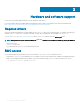
2 Hardware and software support For the most current BMC update information, see the VEP4600 Release Notes. For more information about the intelligent platform management interface (IPMI), see the IPMI resources that are hosted by Intel at https://www.intel.com/content/www/us/en/servers/ipmi/ipmi-technical-resources.html. Required drivers In Linux, the baseboard management controller (BMC) uses the ipmitool open-source tool during testing.
3 BMC web GUI GUI interface for BMC functionality. The intuitive BMC web browser base GUI permits users to access BMC functionality with the following menus: • Sensor • FRU Information • Logs & Reports • Settings • Power Control • Maintenance • Sign Out Topics: • Login • Dashboard • FRU information • Logs & Reports • Settings • Power control • Maintenance Login Enter Username and password.
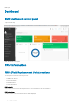
BMC login Dashboard BMC dashboard control panel Top level monitoring. BMC dashboard control panel FRU information FRU (Field Replacement Units) sections The FRU panel contains the following sections: • Available FRU devices • Chassis information • Board information • Product information FRU Device ID Select a FRU Device ID from the drop-down lists to view the details of the selected device. FRU Device Name The device name of the selected FRU device will be displayed.
FRU screen Logs & Reports Contains IPMI event log, System log, and Audit log screens. IPMI Event Log IPMI Event Log sections: • This page displays the list of events incurred by different sensors on this device. Click on a record to see the details of that entry. • You can use the sensor type or sensor name filter options to view those specific events logged in the device. • Click Clear Event Logs option to delete all existing records for all sensors.
IPMI Event Log screen System Log System log sections: • This page displays logs of system events for this device (if the options have been configured). NOTE: Logs have to be configured under Settings -> Log Settings ->Advanced Log Settings in order to display any entries. System log screen Audit Log Audit log sections: • This page displays logs of system events for this device (if the options have been configured).
Audit log screen Settings The Settings screen include the following sections: • Date & Time • External User Services • Log settings • Network settings • PAM order settings • Platform event filter • SMTP settings • SSL settings • System firewall • User mnagement BMC web GUI 13
Settings screen Date & time Date & time sections: • NOTE: If the timezone is selected from the group of manual offset(GMT/ETC timezones), the map selection will be disabled. The TimeZone settings will be reflected only after saving the settings. External user services External user services sections: • LDAP/E-directory settings • Active directory settings • RADIUS settings Setup each External user service using the options supplied.
External user services screen Log settings Log settings sections: • SEL Log settings policy • Advanced log settings Setup each Log settings section using the options supplied.
SEL Log settings SEL settings: This field is used to configure the log policy for the event log. SEL log settings screen Network settings Network sections: • Network IP settings • Network link configuration • DNS configuration Setup each Log settings section using the options supplied. Network settings screen Network IP settings Enable LAN Check this option to enable LAN support for the selected interface.
Select the LAN interface to be configured. MAC address This field displays the MAC address of the selected interface (read only). Enable IPv4 Check this option to enable IPv4 support for the selected interface. Enable IPv4 DHCP Check this option to enable IPv4 DHCP support to dynamically configure IPv4 address using Dynamic Host Configuration Protocol (DHCP). IPv4 Address If DHCP is disabled, specify a static Subnet Mask to be configured for the selected interface.
• Value ranges from 1 to 4094. NOTE: VLAN ID cannot be changed without resetting the VLAN configuration. VLAN ID 0, 4095 are reserved VLAN ID's. VLAN Priority Specify the priority for VLAN configuration. • Value ranges from 0 to 7. NOTE: 7 is the highest priority for VLAN.
PAM order settings • PAM authentication order This page is used to configure the PAM order for user authentication into the BMC. It shows the list of available PAM modules supported in the BMC. Click and Drag the required PAM module to change its order.
Setup each Platform event filters section using the options supplied. Platform event filters screen Event filters Event filters options: • All • Configured • Unconfigured Displays all configured Event filters and available slots. You can modify or add new event filter entry. By default, 15 Event filter entries are configured among the 40 available slots. 1 Choose All option to view available configured and unconfigured slots.
Event filters • • • All Configured Unconfigured Displays all configured Event filters and available slots. You can modify or add new event filter entry. By default, fifteen Event filter entries are configured among the 40 available slots. 1 Choose All option to view available configured and unconfigured slots. 2 Choose Configured option to view available Configured slots which are in Enabled/Disabled.
Choose a particular destination from the configured destination drop-down menu list. Destination Selector Select a destination from the drop-down menu. NOTE: LAN Destination have to be configured - under Configuration->PEF->LAN Destination. Event Specific Alert String Check the box to specify an event-specific Alert String.
LAN destinations LAN destinations sections: Displays configured LAN destinations and available slots. You can modify or add new LAN destination entry from here. Click X icon to delete the LAN destination entry from the list. A maximum of 15 slots are available. 1 Select the LAN Channel: Select the LAN Channel from the list to be configured. 2 Send Test Alert: Select a configured slot and click Send Test Alert to send sample alert to configured destination.
If Destination type is Email Alert, then choose the user to whom the email alert has to be sent.NOTE: Email address for the user has to be configured under Settings->Users Management. Email Subject These fields must be configured if email alert is chosen as destination type. An email will be sent to the configured email address of the user in case of any severity events with a subject specified in subject field and will contain the message field's content as the email body.
Select the LAN interface to be configured. Sender Email ID Enter the valid Sender Email ID on the SMTP Server. Maximum allowed size for Email ID is 64 bytes which includes username and domain name. Primary SMTP Support Check this option to enable SMTP support for the BMC. Primary Server Name Enter the 'Machine Name' of the SMTP Server.This field is for Information Purpose Only. • Machine Name is a string of maximum 25 alpha-numeric characters. • Space, special characters are not allowed.
Enter the password for the SMTP User Account. • Password must be at least 4 characters long. • White space is not allowed. NOTE: This field will not allow more than 64 characters. Primary SMTP SSLTLS Enable Check the option Enable to enable SMTP SSLTLS protocol. Primary SMTP STARTTLS Enable Check the option Enable to enable SMTP STARTTLS protocol. Secondary SMTP Support Check this option to enable Secondary SMTP support for the BMC.
SSL settings SSL sections: • View SSL certificate • Generate SSL certificate • Upload SSL certificate Setup each SSL settings section using the options supplied. SSL settings screen View SSL Certificate Current Certificate Information Displays basic information about the uploaded SSL certificate with the following fields: • Version- Serial Number • Signature Algorithm • Public Key It displays the basic information about the uploaded SSL certificate.It displays the following fields.
It displays about the information to whom the certificate is issued: • Common Name(CN) • Organization(O) • Organization Unit(OU) • City or Locality(L) • State or Province(ST) • Country(C) • Email Address SSL Certificate screen Generate SSL certificate Common Name (CN) 28 BMC web GUI
Common name for which the generated certificate: • Maximum length of 64 characters. • It is a string of alpha-numeric characters. • Special characters '#' and '$' are not allowed. It displays the basic information about the uploaded SSL certificate.It displays the following fields. Organization (O) Organization name for which certificate to be generated: • Maximum length of 64 characters. • It is a string of alpha-numeric characters. • Special characters '#' and '$' are not allowed.
Generate SSL certificate screen Upload SSL certificate Current certificate The information as Current certificate and uploaded date/time will be displayed (read-only). New certificate Browse and navigate to the certificate file: • Certificate file should be of pem type. Current private key The information as current private key and uploaded date/time will be displayed (read-only).
Upload SSL certificate screen System firewall • System firewall order This page is used to configure the System firewall order for user authentication into the BMC. It shows the list of available System firewall modules supported in the BMC.
General firewall settings General firewall settings screen The Settings screen include the following sections: • Existing firewall settings • Add firewall settings General firewall settings screen Existing firewall settings This page displays list of general firewall configurations. Click X icon to delete an item from the list. To view the page, user must at least be an Operator. To add or delete a firewall, user must be an Administrator.
The respective firewall rule effect will end from this time.
IP address firewall rules screen Existing IP Rules This page displays list of Existing IP firewall rules. Click X icon to delete an item from the list. To view the page, user must at least be an Operator. To add or delete a firewall, user must be an Administrator. Add IP Rule IP Single (or) Range Start This field is used to configured the IP address or Range of IP addresses. An IP address will support IPv4 address format only: • IPv4 Address made of 4 numbers separated bydots as in xxx.xxx.xxx.xxx.
Add IP rule screen Port firewall rules Port firewall rules screen The port firewall rules screen include the following sections: • Existing port rules • Add new port rule BMC web GUI 35
Port firewall rules screen Existing port Rules This page displays list of Existing port firewall rules. Click X icon to delete an item from the list. To view the page, user must at least be an Operator. To add or delete a firewall, user must be an Administrator. Add port rule Port Single (or) Range Start This field is used to configure the port address or range of port addresses. A port address will support portv4 address format only: • Port value ranges from 1 to 65535.
Add port rule screen User management • User management order This page is used to configure the User management order for user authentication into the BMC. It shows the list of available User management modules supported in the BMC. The list below shows the current list of available users by channel. To Add or Edit a user, click on icon. To Delete a particular user from the list, click icon. A maximum of 10 slots are available and include the default of admin and anonymous.
User management screen User management configuration Username Enter the name of the new user: • IP Address consists of four sets of numbers separated by dots as in 'xxx.xxx.xxx.xxx'. • Each set ranges from 0 to 255. • First Number must not be 0. Change Password Select this option to change the password. Password Size Select the Size of the password. Password Enter a strong password which consist of atleast one upper case letter, alphanumeric and special characters.
• Administrator • Operator • None SNMP Access Check the box to enable SNMP access for the user. SNMP Authentication Protocol Choose an Authentication Protocol for SNMP settings. NOTE: Password field is mandatory, if Authentication protocol is changed. SNMP Privacy Protocol Choose the Encryption algorithm to use for SNMP settings. Email Format Check this option to enable IPv6 DHCP to dynamically configure IPv6 address using Dynamic HostConfiguration v6 Protocol (DHCPv6).
User management configuration screen Power control Power off Select this option to immediately power off the server. Power on Select this option to power on the server. Power Cycle Select this option to first power off, and then reboot the system (cold boot). Hard reset Select this option to reboot the system without powering off (warm boot). Select this option to initiate operating system shutdown prior to the shutdown..
Power control screen Maintenance The Maintenance screen include the following sections: • Backup configuration • Dual image configuration • Firmware image location • Firmware information • Preserve configuration • Restore configuration • Restore factory defaults • System administrator Maintenance screen Backup configuration Check the configuration that needs to be backed up. Use the downloaded to restore the configuration.
Backup configuration screen Firmware image location Image location type Protocol to be used to transfer the firmware image into the BMC.
Describes the BMC Active Image ID. Active image ID Describes the Build Date of the active BMC image Build Time Describes the Build Time of the active BMC image Firmware version Describes the Firmware version of the active BMC image Firmware information screen Preserve configuration Restore Configuration Check the configuration that needs to be preserved, while the Restore Configuration is done. Check All Select this option to check all the configuration list.
Preserve configuration screen Restore configuration Config file Use Browse button to navigate to the Configuration file.
Restore factory defaults Preserve configuration page Use Browse button to navigate to the Configuration file. To preserve any existing configuration data, goto preserve configuration page and select them. Restore factory defaults screen System Administrator Username Username of System Administrator is displayed (read only). Enable User Access Check this option to enable user access for system administrator. Change Password Check this option to change the existing password.
Enter the new password here. • Password must be at least 8 characters long. • White space is not allowed. NOTE: This field will not allow more than 64 characters. Confirm Password Enter the same password which you have entered in the Password field to confirm the Password. • Password must be at least 8 characters long. • White space is not allowed. NOTE: This field will not allow more than 64 characters.
4 Configuration methods The diagnostic operating software (DIAG OS) running on the local processor has ipmitool installed by default. You can use the ipmitool both at the switch and remotely. NOTE: The information in the following chapter is intended for developers and system administrators. Users are recommended to use the Web GUI as described BMC web GUI chapter. Accessing BMC from the host does not require user name or password.
| 1.358 Power_Status | na Watchdog2 | na SEL | na BMC boot | na Outlet_Temp | na Inlet1_Temp | na Inlet2_Temp | na Inlet3_Temp | na Inlet4_Temp | na Fan1 | na Fan2 | na Fan3 | na | 0x0 | discrete | 0x0180| na | na | na | na | na | 0x0 | discrete | 0x0080| na | na | na | na | na | 0x0 | discrete | 0x0080| na | na | na | na | na | 0x0 | discrete | 0x0180| na | na | na | na | na | 31.000 | degrees C | ok | na | na | na | na | na | 25.
Outlet_Temp | na Inlet1_Temp | na Inlet2_Temp | na Inlet3_Temp | na Inlet4_Temp | na Fan1 | na Fan2 | na Fan3 | na Fan4 | na Fan5 | na Fan1_Status | na Fan2_Status | na Fan3_Status | na Fan4_Status | na Fan5_Status | na | 30.000 | degrees C | ok | na | na | na | na | na | 26.000 | degrees C | ok | na | na | na | na | na | 22.000 | degrees C | ok | na | na | na | na | na | 22.000 | degrees C | ok | na | na | na | 59.000 | 62.000 | 29.
Configurations LAN configurations For network settings, see the IPMI Specification v2.0 chapter 23.1 Set LAN Configuration Parameters Command and Table 23-4 LAN Configuration Parameters. In addition to setting IP addresses, use ipmitool to set the network mask, MAC address, default gateway IP and MAC addresses, and so forth. ipmitool commands: root@dellemc-diag-os:~# ipmitool lan set 1 usage: lan set LAN set command/parameter options: ipaddr
Dell EMC recommends executing the LAN settings command from a system-side machine rather than from a remote machine. To set a dynamic host configuration protocol (DHCP) IP address, use the following command: # ipmitool lan set 1 ipsrc dhcp To set a static IP address: # ipmitool lan set 1 ipsrc static # ipmitool lan set 1 ipaddr You can also add the BMC IP address from the BIOS. For more information, see the BIOS manual at https://www.dell.com/support.
Byte 11(0xff) - sensor number(any) Byte 12(0x01) – event trigger(threshold) The entry 2 is changed after the command, as shown: # ipmitool pef filter list 1 | enabled, configurable | Any | Any | None | OEM | Any | Alert,OEM-defined | 1 2 | enabled, pre-configured | Any | Any | Information | OEM | Any | Alert | 2 For more information, see the IPMI Specification v2.0 chapter 17.7 Event Filter Table and chapter 30.3 Set PEF Configuration Parameters Command.
Retry Interval Number of Retries Alert Gateway Alert IP Address Alert MAC Address : : : : : 3 3 Default 10.11.227.180 00:00:00:00:00:00 Alert policy setup To setup the alert policy, you must use the ipmitool raw command. To view the current policy table, use the ipmitool pef policy list command. # ipmitool pef policy list 1 | 1 | disabled | Match-always | 1 | 802.3 LAN | PET | AMI | 0 | 0 | 0.0.0.0 | 00:00:00:00:00:00 2 | 2 | disabled | Match-always | 1 | 802.3 LAN | PET | AMI | 0 | 0 | 0.0.0.
2 Set the privilege level for the user in Step 1 using the following: $ ./ipmitool -H xx.xx.xxx.
Board Serial Board Part Number : CNDED0081G01GL : 0GRTNKA02 FRU Device Description : FRU_FAN1 (ID 3) Unknown FRU header version 0x00 FRU Device Description Board Mfg Date Board Mfg Board Product Board Serial Board Part Number Product Manufacturer Product Name Product Version Product Serial Product Asset Tag : : : : : : : : : : : FRU_FAN2 (ID 4) Mon Feb 12 08:01:00 2018 Dell CNCES008260036 07CRC9X01 Dell D4SSG02 For more information, see the IPMI Specification v2.0 chapter 22.
– [7:4]-Reserved – [3:0]-User simultaneous session limit. 1=based. oh=only limited by the implementations support for simultaneous sessions. • Response data byte 1—Completion code NOTE: If the user access level is set higher than the privilege limit for a given channel, the implementation does not return an error completion code. If required, It is up to the software to check the channel privilege limits set using the Set Channel Access command and provide notification of any mismatch.
Firewall To set a firewall, use the set firewall configuration command. Use parameters 0–3 to add the iptables rules and 4–7 to remove the iptables rules.
Parameter # Parameter data [5:8]—Ending IP address until IPs are blocked or unblocked based on the state. For example, if the IP address is x1.x2.x3.x4, the format is: 1st byte = x1 2nd byte = x2 3rd byte = x3 4th byte = x4 Add the IPv4 port number rule 2 Data 1:—Protocol TCP/UDP 0 = TCP 1 = UDP 2 = both TCP and UDP Data 2:3—port number [2:3]—MX byte first. Port number blocked or unblocked based on the state.
Parameter # Parameter data 4th byte = x4 Remove the IPv4 port number rule 6 Data 1:—Protocol TCP/UDP 0 = TCP 1 = UDP 2 = both TCP and UDP Data 2:3—port number [2:3]—Port number from the ports blocked or unblocked based on the state. Remove the IPv4 port range rule 7 Data 1:—Protocol TCP and UDP 0 = TCP 1 = UDP 2 = both TCP and UDP Data 2:5—port range [2:3]—Port number from the ports blocked or unblocked based on the state. [4:5]—Port number till ports are blocked or unblocked based on the state.
Parameter # Parameter data Date 5:10—Start time [5:6]—Year LS-byte first if little endian system. Twobyte data required to form year. 7—month 8—date 9—hour 10—minute Date 11-16—stop time [11:12]—Year LS-byte first if little endian system. Twobyte data required to form year. 13—month 14—date 15—hour 16—minute Add IPv4 range of addresses with timeout rule 12 Data 1:8—IP address [1:4]—Starting IP address blocked or unblocked based on the state.
Parameter # Parameter data 1 = UDP 2 = both TCP and UDP Data 2:3—port number [2:3]—Port number from the ports blocked or unblocked based on the state. Date 4:9—Start time [4:5]—Year LS-byte first if little endian system. Twobyte data required to form year. 6—month 7—date 8—hour 9—minute Date 10-15—stop time [10:11]—Year LS-byte first if little endian system. Twobyte data required to form year.
Parameter # Parameter data 9—date 10—hour 11—minute Date 12-17—stop time [12:13]—Year LS-byte first if little endian system. Twobyte data required to form year. 14—month 15—date 16—hour 17—minute Remove the IPv4 address with timeout rule 15 Data 1:4—IP address MS-byte first. The IPv4 address type blocked or unblocked based on the state. Date 5:10—Start time [5:6]—Year LS-byte first if little endian system. Twobyte data required to form year.
Parameter # Parameter data Date 9:14—Start time [9:10]—Year LS-byte first if little endian system. Twobyte data required to form year. 11—month 12—date 13—hour 14—minute Date 15-20—Stop time [15:16]—Year LS-byte first if little endian system. Twobyte data required to form year.
Parameter # Parameter data LS-byte first if little endian system. Twobyte data required to form year. 12—month 13—date 14—hour 15—minute Remove the IPv4 port number range with timeout rule 18 Data 1:—Protocol TCP and UPD 0 = TCP 1 = UDP 2 = both TCP and UDP Data 2:5—port number [2:3]—Port number from the ports blocked or unblocked based on the state. [4:5]—Port number till the ports blocked or unblocked based on the state. Date 6:11Start time [6:7]—Year LS-byte first if little endian system.
Parameter # Parameter data Bit 7:2—Reserved Bit 1—IPv6 Bit 0—IPv4 Date 2:7—Start time [2:3]—Year LS-byte first if little endian system. Twobyte data required to form year. 4—month 5—date 6—hour 7—minute Date 8:13—Stop time [8:9]—Year LS-byte first if little endian system. Twobyte data required to form year. 10—month 11—date 12—hour 13—minute Remove drop all Ipv4 or IPv6 with timeout rule 20 Add iptables rules to block IPv4 and IPv6 traffic to the BMC. The state selector is not used.
Parameter # Parameter data Date 8:13—Stop time [8:9]—Year LS-byte first if little endian system. Twobyte data required to form year. 10—month 11—date 12—hour 13—minute Add IPv6 address with timeout rule 21 Data 1:16—IPv6 address MS-byte first. The IPv6 address type blocked or unblocked based on the state. Date 7:22—Start time [17:18]—Year LS-byte first if little endian system. Twobyte data required to form year.
Parameter # Parameter data LS-byte first if little endian system. Twobyte data required to form year. 35—month 36—date 37—hour 38—minute Date 39:44—stop time [39:40]—Year LS-byte first if little endian system. Twobyte data required to form year. 41—month 42—date 43—hour 44—minute Remove the IPv6 address with timeout rule 23 Data 1:16—IPv6 address MS-byte first. The IPv4 address type blocked or unblocked based on the state. Date 17:22—Start time [17:18]—Year LS-byte first if little endian system.
Parameter # Parameter data [1:16]—Port number from the ports blocked or unblocked based on the state. [17:32]—Port number till the ports blocked or unblocked based on the state. Date 33:38—Start time [33:34]—Year LS-byte first if little endian system. Twobyte data required to form year. 35—month 36—date 37—hour 38—minute Date 39:44—stop time [39:40]—Year LS-byte first if little endian system. Twobyte data required to form year.
Parameter # Parameter data Date 10-15—stop time [10:11]—Year LS-byte first if little endian system. Twobyte data required to form year. 12—month 13—date 14—hour 15—minute Add the IPv6 port number range with timeout rule 26 Data 1—Protocol TCP and UDP 0 = TCP 1 = UDP 2 = both TCP and UDP Data 2:5—port number [2:3]—Port number from the ports blocked or unblocked based on the state. [4:5]—Year Date 6:11—Start time [6:7]—Year LS-byte first if little endian system. Twobyte data required to form year.
Parameter # Parameter data 1 = UDP 2 = both TCP and UDP Data 2:3—port number [2:3]—Port number from the ports blocked or unblocked based on the state. [4:9]—Year Date 4:9—Start time [4:5]—Year LS-byte first if little endian system. Twobyte data required to form year. 6—month 7—date 8—hour 9—minute Date 10-15—stop time [10:11]—Year LS-byte first if little endian system. Twobyte data required to form year.
Parameter # Parameter data 8—month 9—date 10—hour 11—minute Date 12-17—stop time [12:13]—Year LS-byte first if little endian system. Twobyte data required to form year. 14—month 15—date 16—hour 17—minute Add the IPv6 address rule 29 Data 1:16—IPv6 address MS-byte first. This is an IPv6 address that is blocked or unblocked based on state. Add the IPv6 address range rule 30 Data 1:16—IPv6 address range [1:16]—Starting IP address from which IPs are blocked or unblocked based on the state. [17.
Parameter # Parameter data 0 = TCP 1 = UDP 2 = both TCP and UDP Data 2:5—port number [2:3]—Port number from the ports blocked or unblocked based on the state. [4:5]—Port number till the ports are blocked or u nblocked based on the state. Remove the IPv6 port number rule 35 Data 1—Protocol TCP and UDP 0 = TCP 1 = UDP 2 = both TCP and UDP Data 2:3—port number [2:3]—Port number from the ports blocked or unblocked based on the state.
• Response data byte 2—Reservation ID, LS byte 0000h reserved. • Response data byte 3—Reservation ID, SM byte Get SEL command • Request data byte 1:2—Reservation IS, LS byte first. Only required for a partial get. Otherwise use 0000h. • Request data byte 3:4—SEL record ID, LS byte first. – 0000h=GET FIRST ENTRY – FFFFh=GET LAST ENTRY • Request data byte 5—Offset into record • Request data byte 6—Bytes to read. FFH means read entire record. • Response data byte 1—Completion code.
– NOTE: These request data bytes are required only when you enable either the local or remote system log. 64bytes : Hostname (ASCII) Remote syslog server 4bytes : port number To set the remote server ip address to 10.0.124.22 and port to 770: ipmitool -I lanplus -H xx.xx.xx.
• Response data byte 1—Completion code – 0x83—Authentication feature is not enabled – 0x84—NTP feature is not enabled – 0x85—KVM feature is not enabled – 0x86—SNMP feature is not enabled Configuration methods 75
5 Firmware upgrades Manual or automatic BMC, BIOS, and CPLD firmware upgrades is required before VEP4600 Expansion Card installation. NOTE: Minimum firmware requirements Table 4. Required firmware minimum release requirements. Device Firmware Minimum firmware release required when installing an rNDC Card Minimum firmware release required when installing the WIFI or LTE Card VEP4600 BMC v1.22 v1.23 BIOS v3.41.0.9-10 3.41.0.9-13 CPLD V0C V0C DIAGS OS 3.41.3.81-4 3.41.3.
puTTY 115200 baud rate setup BIOS access process 1 Press the delete button after the POST Lower DRAM Memory test appears on the screen. Continue pressing the delete button to progress to the BIOS setup and configuration screen. NOTE: If the BIOS setup and configuration screen window passes, power off and power on the platform again to restart the boot up process. Figure 2.
Figure 3. Boot up screen Figure 4. BIOS setup and configuration screen 2 Grab the scrollbar on the right side of the console window and scroll it up to display BIOS and CPLD versions. Figure 5. Display BIOS and CPLD versions Configure BIOS and boot into DIAG OS Boot into BIOS setting and select Boot Option #1 to boot from the hard disk.
Figure 6. Select boot from hard disk Select Save & Exit setup and select Yes. Figure 7. Save and exit Type root/calvin to login. Figure 8. Type root/calvin to login Update BMC in DIAG OS Use the following DIAG OS command to update BMC: updatetool -D MAIN-BMC -U -e ./VEP4600-BMC-vx.xx.
NOTE: Switch to BMC console to monitor the BMC update status. Confirm BMC updates. Reboot the system. Proceed to BIOS update. Use this command to update BMC: NOTE: This is the file from the USB drive that is mounted. #updatetool -D MAIN-BMC -U - e You are prompted for confirmation. Press y and enter to continue. When the update is complete, you must powercycle the system.
Verifying Firmware Image : 100%... done Flashing [ast2500e] Module .... Flashing Firmware Image : 100%... done Verifying Firmware Image : 100%... done Resetting the firmware.......... write MAIN-BMC image success Enable device protect Update MAIN-BMC image success root@dellemc-diag-os:~# Update BIOS in DIAG OS Use the following DIAG OS command to update BIOS: NOTE: For updating BIOS and preserving NVRAM(configuration information in BIOS) use the command: updatetool -D BIOS -N -U -e VEP4600-BIOS-x.xx.x.
NOTE: After successfully updating the firmware, power-off and power-on the unit. Make sure all the versions are current and correct. updatetool -D CPLD --index=1 -U -e root@dellemc-diag-os:~# updatetool -D CPLD --index=1 -U -e 00 Disable device protect Disable CPLD protect operation success, wait HW reset Write image to CPLD INFO: Yafu INI Configuration File not found... Default options will not be applied... Creating IPMI session via USB...
Continue pressing the delete button to progress to the BIOS setup and configuration screen. NOTE: If the BIOS setup and configuration screen window passes, power off and power on the platform again to restart the boot up process. 2 Boot into BIOS settings. Figure 9. Boot into BIOS settings 3 Go to Server Mgmt->BMC network configuration. Figure 10. BMC network configuration 4 Select Lan channel 1 and configure IP address.
Figure 12. Save & Exit Network interface settings 1 After booting up, go to BMC console to check the network interface settings. ifconfig eth0 Link encap:Ethernet HWaddr 54:BF:64:A9:E7:C9 inet addr:xxx.xx.xxx.xx Bcast:xxx.xx.xxx.xxx Mask:255.255.255.
Check BIOS, BMC, CPLD versions 1 After booting up the system, check BIOS and CPLD by scroll up the vertical scroll bar on the right in putty session: BIOS Boot Selector for VEP-4600 Primary BIOS Version x.xx.x.x-xx CPLD Version:x.x CPLD Reset Source=0x44 2 Check the BMC version in BIOS settings: Figure 13.
6 Remote power cycle system ipmitool remote BMC, DIAG OS power cycle shell commands. Remote BMC, DIAG OS power cycle Run ipmitool from the BMC serial console command prompt. a Use this command to power cycle a remote system. # ipmitool -H xxx.x.x.x -U admin -P admin power cycle If BMC has a different administrator configured, replace the -u and -p parameters with admin\admin NOTE: Username and password must be admin\admin • -u—admin • -p—admin ~ # ipmitool -H xxx.x.x.
[610 : 685 INFO]Power Consumption Mode Value Updated (1): Remote ipmitool DIAG OS power management Use ipmitool to reboot and power-off from the BMC serial console command prompt. NOTE: When building the kernel for VEP4600, the kernel flag CONFIG_IPMI_POWEROFF should be set to n. Having this flag turned on will cause the kernel to send the ipmi command to power down the chassis when the CPU is powered-off. For example, pressing the push button for five seconds will power down the CPU.
7 Access system health sensors To check sensor information, use the following command: root@dellemc-diag-os:~# ipmitool sensor list To change the sensor threshold, see the IPMI Specification v2.0 chapter 35.8 Set Sensor Thresholds Command. • Request data byte 1—Sensor number, FFH=reserved • Request data byte 2— – [7:6] - reserved.
PSU1_Chass_temp | 28.000 80.000 | 85.000 PSU2_Normal_temp | 37.000 80.000 | 85.000 PSU2_Sys_temp | 30.000 80.000 | 85.000 PSU2_Chass_temp | 29.000 80.000 | 85.000 CPU_temp | 35.000 60.000 | 68.000 DRAM1_temp | 33.000 60.000 | 68.000 DRAM2_temp | 0.000 60.000 | 68.000 FAN1_Rear_rpm | 6570.000 15390.000 | na FAN2_Rear_rpm | 6570.000 15390.000 | na FAN3_Rear_rpm | 6570.000 15390.000 | na FAN4_Rear_rpm | 6570.000 15390.000 | na FAN1_Front_rpm | 6570.000 15390.000 | na FAN2_Front_rpm | 6570.000 15390.
na | na FAN3_prsnt | 0x1 na | na FAN4_prsnt | 0x1 na | na Fan1_Rear_state | 0x0 na | na Fan2_Rear_state | 0x0 na | na Fan3_Rear_state | 0x0 na | na Fan4_Rear_state | 0x0 na | na Fan1_Front_state | 0x0 na | na Fan2_Front_state | 0x0 na | na Fan3_Front_state | 0x0 na | na Fan4_Front_state | 0x0 na | na root@dellemc-diag-os:~# 90 Access system health sensors | discrete | 0x0180| na | na | na | na | | discrete | 0x0180| na | na | na | na | | discrete | 0x0080| na | na | na | na | | discrete
8 Access FRU data To check field replacement unit (FRU) data, use the following command: root@dellemc-diag-os:~# ipmitool fru print For more FRU information, see the IPMI Specification v2.0 chapter 34.2 Read FRU Data Command. • Request data 1—FRU device ID. FFh=reserved • Request data 2—FRU inventory offset to read, LS byte • Request data 3—FRU inventory offset to read, LS byte – Offset is in bytes or words-per-device. Access type returned in the Get FRU Inventory Area Info command output.
Board Mfg Date : Mon May 14 13:44:00 2018 Board Mfg : DELL Board Product : Board Serial : TW0M6X8JDNT008570208 Board Part Number : 0M6X8JX01FRU Device Description : FRU_PSU1 (ID 6) Board Mfg Date : Fri Jan 5 20:43:00 2018 Board Mfg : DELL Board Product : PWR SPLY,1600W,RDNT,DELTA Board Serial : CNDED0081500XQ Board Part Number : 095HR5A04FRU Device Description : FRU_PSU2 (ID 7) Board Mfg Date : Fri Jan 5 20:51:00 2018 Board Mfg : DELL Board Product : PWR SPLY,1600W,RDNT,DELTA Board Serial : CNDED0081506H8 B
9 ipmiutil package NOTE: All commands are subject to change as the ipmiutil package evolves over time. For more information about the IPMI utility, use cases, and the newest list of subcommands, see the IPMI website that is hosted by Intel at https://www.intel.com/ content/www/us/en/servers/ipmi/ipmi-technical-resources.html. • ipmiutil—a metacommand to invoke each of the following functions: – ipmiutil alarms (ialarms)—show and set the front panel alarms, including light emitting diodes (LEDs) and relays.
10 Dell EMC support The Dell EMC support site provides documents and tools to help you effectively use Dell EMC equipment and mitigate network outages. Through the support site you can obtain technical information, access software upgrades and patches, download available management software, and manage your open cases. The Dell EMC support site provides integrated, secure access to these services. To access the Dell EMC support site, go to www.dell.com/support/.