
Service Manual


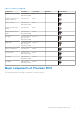

Table Of Contents
- Precision 5570 Service Manual
- Contents
- Working inside your computer
- Removing and installing components
- Drivers and downloads
- System setup
- Troubleshooting
- Handling swollen Lithium-ion batteries
- Locate the Service Tag or Express Service Code of your Dell computer
- System diagnostic lights
- SupportAssist diagnostics
- Built-in self-test (BIST)
- Recovering the operating system
- WiFi power cycle
- Drain residual flea power (perform hard reset)
- Backup media and recovery options
- Real Time Clock—RTC reset
- Getting help and contacting Dell

Removing and installing components
NOTE: The images in this document may differ from your computer depending on the configuration you ordered.
Recommended tools
The procedures in this document may require the following tools:
● Phillips screwdriver #0
● Phillips screwdriver #1
● Torx #5 (T5) screwdriver
● Plastic scribe
Screw list
NOTE: When removing screws from a component, it is recommended to note the screw type, the quantity of screws, and
then place them in a screw storage box. This is to ensure that the correct number of screws and correct screw type is
restored when the component is replaced.
NOTE: Some computers have magnetic surfaces. Ensure that the screws are not left attached to such surfaces when
replacing a component.
NOTE: Screw color may vary with the configuration ordered.
Table 1. Screw list
Component Secured to Screw type Quantity Screw image
Base cover Palm-rest and
keyboard assembly
M2x3 8
Battery Palm-rest and
keyboard assembly
M2x3 4
Battery Palm-rest and
keyboard assembly
M2x4 4
Right fan System board and
palm-rest and
keyboard assembly
M2x4 1
I/O board shield I/O board M2x4 1
Left fan System board and
palm-rest and
keyboard assembly
M2x4 2
Solid-state drive 1 System board M2x2 1
Solid-state drive 2 System board M2x2 1
2
8 Removing and installing components