
Users Guide


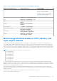

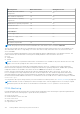
Table Of Contents
- Integrated Dell Remote Access Controller 9 User's Guide
- Contents
- Overview of iDRAC
- Benefits of using iDRAC
- Key features
- New features added
- How to use this guide
- Supported web browsers
- iDRAC licenses
- Licensed features in iDRAC9
- Interfaces and protocols to access iDRAC
- iDRAC port information
- Other documents you may need
- Contacting Dell
- Accessing documents from Dell support site
- Accessing Redfish API Guide
- Logging in to iDRAC
- Force Change of Password (FCP)
- Logging into iDRAC using OpenID Connect
- Logging in to iDRAC as local user, Active Directory user, or LDAP user
- Logging in to iDRAC as a local user using a smart card
- Logging in to iDRAC using Single Sign-On
- Accessing iDRAC using remote RACADM
- Accessing iDRAC using local RACADM
- Accessing iDRAC using firmware RACADM
- Simple 2-Factor Authentication (Simple 2FA)
- RSA SecurID 2FA
- Viewing system health
- Logging in to iDRAC using public key authentication
- Multiple iDRAC sessions
- Secure default password
- Changing the default login password
- Enabling or disabling default password warning message
- Password Strength Policy
- IP Blocking
- Enabling or disabling OS to iDRAC Pass-through using web interface
- Enabling or disabling alerts using RACADM
- Setting up managed system
- Setting up iDRAC IP address
- Modifying local administrator account settings
- Setting up managed system location
- Optimizing system performance and power consumption
- Setting up management station
- Configuring supported web browsers
- Configuring Internet Explorer
- Configuring Mozilla Firefox
- Configuring web browsers to use virtual console
- Viewing localized versions of web interface
- Updating device firmware
- Updating firmware using iDRAC web interface
- Scheduling automatic firmware updates
- Updating device firmware using RACADM
- Updating firmware using CMC web interface
- Updating firmware using DUP
- Updating firmware using remote RACADM
- Updating firmware using Lifecycle Controller Remote Services
- Updating CMC firmware from iDRAC
- Viewing and managing staged updates
- Rolling back device firmware
- Easy Restore
- Monitoring iDRAC using other Systems Management tools
- Support Server Configuration Profile — Import and Export
- Secure Boot Configuration from BIOS Settings or F2
- BIOS recovery
- Plugin Management
- Configuring iDRAC
- Viewing iDRAC information
- Modifying network settings
- Cipher suite selection
- FIPS mode
- Configuring services
- Using VNC client to manage remote server
- Configuring front panel display
- Configuring time zone and NTP
- Setting first boot device
- Enabling or disabling OS to iDRAC Pass-through
- Obtaining certificates
- Configuring multiple iDRACs using RACADM
- Disabling access to modify iDRAC configuration settings on host system
- Delegated Authorization using OAuth 2.0
- Viewing iDRAC and managed system information
- Viewing managed system health and properties
- Configuring Asset Tracking
- Viewing system inventory
- Viewing sensor information
- Monitoring performance index of CPU, memory, and input output modules
- Idle Server Detection
- GPU (Accelerators) Management
- Checking the system for Fresh Air compliance
- Viewing historical temperature data
- Viewing network interfaces available on host OS
- Viewing network interfaces available on host OS using RACADM
- Viewing FlexAddress mezzanine card fabric connections
- Viewing or terminating iDRAC sessions
- Setting up iDRAC communication
- Communicating with iDRAC through serial connection using DB9 cable
- Configuring BIOS for serial connection
- Enabling RAC serial connection
- Enabling IPMI serial connection basic and terminal modes
- Switching between RAC serial and serial console while using DB9 cable
- Communicating with iDRAC using IPMI SOL
- Communicating with iDRAC using IPMI over LAN
- Enabling or disabling remote RACADM
- Disabling local RACADM
- Enabling IPMI on managed system
- Configuring Linux for serial console during boot in RHEL 6
- Configuring serial terminal in RHEL 7
- Supported SSH cryptography schemes
- Communicating with iDRAC through serial connection using DB9 cable
- Configuring user accounts and privileges
- iDRAC user roles and privileges
- Recommended characters in user names and passwords
- Configuring local users
- Configuring Active Directory users
- Prerequisites for using Active Directory authentication for iDRAC
- Supported Active Directory authentication mechanisms
- Standard schema Active Directory overview
- Configuring Standard schema Active Directory
- Extended schema Active Directory overview
- Configuring Extended schema Active Directory
- Extending Active Directory schema
- Installing Dell extension to the Active Directory users and computers snap-in
- Adding iDRAC users and privileges to Active Directory
- Configuring Active Directory with Extended schema using iDRAC web interface
- Configuring Active Directory with Extended schema using RACADM
- Testing Active Directory settings
- Configuring generic LDAP users
- System Configuration Lockdown mode
- Configuring iDRAC for Single Sign-On or smart card login
- Prerequisites for Active Directory Single Sign-On or smart card login
- Configuring iDRAC SSO login for Active Directory users
- Enabling or disabling smart card login
- Configuring Smart Card Login
- Using Smart Card to Login
- Configuring iDRAC to send alerts
- Enabling or disabling alerts
- Filtering alerts
- Setting event alerts
- Setting alert recurrence event
- Setting event actions
- Configuring email alert, SNMP trap, or IPMI trap settings
- Configuring WS Eventing
- Configuring Redfish Eventing
- Monitoring chassis events
- Alerts message IDs
- iDRAC 9 Group Manager
- Managing logs
- Monitoring and managing power in iDRAC
- iDRAC Direct Updates
- Inventorying, monitoring, and configuring network devices
- Inventorying and monitoring network devices
- Inventorying and monitoring FC HBA devices
- Inventorying and monitoring SFP Transceiver devices
- Telemetry Streaming
- Serial Data Capture
- Dynamic configuration of virtual addresses, initiator, and storage target settings
- Supported cards for IO Identity Optimization
- Supported NIC firmware versions for IO Identity Optimization
- Virtual or Remote assigned Address and Persistence Policy behavior when iDRAC is set to Remote-Assigned Address mode or Console mode
- System behavior for FlexAddress and IO Identity
- Enabling or disabling IO Identity Optimization
- SSD Wear Threshold
- Configuring persistence policy settings
- Managing storage devices
- Understanding RAID concepts
- Supported controllers
- Supported enclosures
- Summary of supported features for storage devices
- Inventorying and monitoring storage devices
- Viewing storage device topology
- Managing physical disks
- Managing virtual disks
- RAID Configuration Features
- Managing controllers
- Configuring controller properties
- Importing or auto importing foreign configuration
- Clearing foreign configuration
- Resetting controller configuration
- Switching the controller mode
- 12 Gbps SAS HBA adapter operations
- Monitoring predictive failure analysis on drives
- Controller operations in non-RAID mode or HBA mode
- Running RAID configuration jobs on multiple storage controllers
- Manage Preserved cache
- Managing PCIe SSDs
- Managing enclosures or backplanes
- Choosing operation mode to apply settings
- Viewing and applying pending operations
- Storage devices — apply operation scenarios
- Blinking or unblinking component LEDs
- Warm reboot
- BIOS Settings
- Configuring and using virtual console
- Supported screen resolutions and refresh rates
- Configuring virtual console
- Previewing virtual console
- Launching virtual console
- Using virtual console viewer
- eHTML5 based virtual console
- HTML5 based virtual console
- Synchronizing mouse pointers
- Passing all keystrokes through virtual console for Java or ActiveX plug-in
- Using iDRAC Service Module
- Using USB port for server management
- Using Quick Sync 2
- Managing virtual media
- Managing vFlash SD card
- Configuring vFlash SD card
- Managing vFlash partitions
- Using SMCLP
- Deploying operating systems
- Troubleshooting managed system using iDRAC
- Using diagnostic console
- Viewing post codes
- Viewing boot and crash capture videos
- Viewing logs
- Viewing last system crash screen
- Viewing System status
- Hardware trouble indicators
- Viewing system health
- Checking server status screen for error messages
- Restarting iDRAC
- Reset to Custom Defaults (RTD)
- Erasing system and user data
- Resetting iDRAC to factory default settings
- SupportAssist Integration in iDRAC
- Frequently asked questions
- System Event Log
- Custom sender email configuration for iDRAC alerts
- Network security
- Telemetry streaming
- Active Directory
- Single Sign-On
- Smart card login
- Virtual console
- Virtual media
- vFlash SD card
- SNMP authentication
- Storage devices
- GPU (Accelerators)
- iDRAC Service Module
- RACADM
- Permanently setting the default password to calvin
- Miscellaneous
- Use case scenarios
- Troubleshooting an inaccessible managed system
- Obtaining system information and assess system health
- Setting up alerts and configuring email alerts
- Viewing and exporting System Event Log and Lifecycle Log
- Interfaces to update iDRAC firmware
- Performing graceful shutdown
- Creating new administrator user account
- Launching servers remote console and mounting a USB drive
- Installing bare metal OS using attached virtual media and remote file share
- Managing rack density
- Installing new electronic license
- Applying IO Identity configuration settings for multiple network cards in single host system reboot

navigate to the System Inventory page to view the details. It may take up to 5 minutes for the information to be available
depending on the hardware installed on the server.
NOTE: CSIOR option is enabled by default.
NOTE: Configuration changes and firmware updates that are made within the operating system may not reflect properly in
the inventory until you perform a server restart.
Click Export to export the hardware inventory in an XML format and save it to a location of your choice.
Viewing sensor information
The following sensors help to monitor the health of the managed system:
● Batteries — Provides information about the batteries on the system board CMOS and storage RAID On Motherboard
(ROMB).
NOTE: The Storage ROMB battery settings are available only if the system has a ROMB with a battery.
● Fan (available only for rack and tower servers) — Provides information about the system fans — fan redundancy and fans
list that display fan speed and threshold values.
● CPU — Indicates the health and state of the CPUs in the managed system. It also reports processor automatic throttling
and predictive failure.
●
Memory — Indicates the health and state of the Dual In-line Memory Modules (DIMMs) present in the managed system.
● Intrusion — Provides information about the chassis.
● Power Supplies (available only for rack and tower servers) — Provides information about the power supplies and the
power supply redundancy status.
NOTE: If there is only one power supply in the system, the power supply redundancy is set to Disabled.
● Removable Flash Media — Provides information about the Internal SD Modules; vFlash and Internal Dual SD Module
(IDSDM).
○ When IDSDM redundancy is enabled, the following IDSDM sensor status is displayed — IDSDM Redundancy Status,
IDSDM SD1, IDSDM SD2. When redundancy is disabled, only IDSDM SD1 is displayed.
○ If IDSDM redundancy is initially disabled when the system is powered on or after an iDRAC reset, the IDSDM SD1 sensor
status is displayed only after a card is inserted.
○ If IDSDM redundancy is enabled with two SD cards present in the IDSDM, and the status of one SD card is online while
the status of the other card is offline. A system reboot is required to restore redundancy between the two SD cards in
the IDSDM. After the redundancy is restored, the status of both the SD cards in the IDSDM is online.
○ During the rebuilding operation to restore redundancy between two SD cards present in the IDSDM, the IDSDM status is
not displayed since the IDSDM sensors are powered off.
NOTE:
If the host system is rebooted during IDSDM rebuild operation, the iDRAC does not display the IDSDM
information. To resolve this, rebuild IDSDM again or reset the iDRAC.
○ System Event Logs (SEL) for a write-protected or corrupt SD card in the IDSDM module are not repeated until they are
cleared by replacing the SD card with a writable or good SD card, respectively.
NOTE:
When iDRAC firmware is updated from versions prior to 3.30.30.30, the iDRAC need to be reset to defaults for
IDSDM settings to appear in the Server Administrator's Platform Event Filter.
● Temperature — Provides information about the system board inlet temperature and exhaust temperature (only applies to
rack servers). The temperature probe indicates whether the status of the probe is within the preset warning and critical
threshold value.
● Voltage — Indicates the status and reading of the voltage sensors on various system components.
The following table provides information about viewing the sensor information using iDRAC web interface and RACADM. For
information about the properties that are displayed on the web interface, see the iDRAC Online Help.
NOTE: The Hardware Overview page displays data only for sensors present on your system.
Table 17. Sensor information using web interface and RACADM
View sensor information For Using web interface Using RACADM
Batteries Dashboard > System Health >
Batteries
Use the getsensorinfo command.
116 Viewing iDRAC and managed system information