Dell EMC OpenManage Server Administrator User's Guide Version 10.1.0.0 June 2021 Rev.
Notes, cautions, and warnings NOTE: A NOTE indicates important information that helps you make better use of your product. CAUTION: A CAUTION indicates either potential damage to hardware or loss of data and tells you how to avoid the problem. WARNING: A WARNING indicates a potential for property damage, personal injury, or death. © 2021 Dell Inc. or its subsidiaries. All rights reserved. Dell, EMC, and other trademarks are trademarks of Dell Inc. or its subsidiaries.
Contents Chapter 1: Introduction................................................................................................................. 6 OMSA Customer Survey....................................................................................................................................................6 Installation.............................................................................................................................................................................
The Server Administrator home page...........................................................................................................................27 Server Administrator user interface differences across modular and non-modular systems...................29 Global Navigation Bar................................................................................................................................................. 29 System Tree...............................................................
Setting Alert actions in Windows Server to Execute Applications........................................................................63 BMC or iDRAC platform events filter alert messages..............................................................................................64 Chapter 8: Troubleshooting.........................................................................................................66 Login Failure Scenarios......................................................................
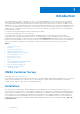
1 Introduction Server Administrator provides a comprehensive, one-to-one systems management solution in two ways: from an integrated, web browser-based graphical user interface (GUI) and from a command line interface (CLI) through the operating system. Server Administrator enables system administrators to manage systems locally and remotely on a network. It enables system administrators to focus on managing their entire network by providing comprehensive one-to-one systems management.
NOTE: When you install the open source packages from the Dell EMC Systems Management Tools and Documentation software, the corresponding license files are automatically copied to the system. When you remove these packages, the corresponding license files are also removed. NOTE: If you have a modular system, install Server Administrator on each server module installed in the chassis.
Storage Management Service The Storage Management Service provides storage management information in an integrated graphical view. NOTE: For more information about the Storage Management Service, see the Dell EMC Server Administrator Storage Management User's Guide at dell.com/openmanagemanuals.
Table 1.
● The Dell Online Diagnostics User's Guide provides complete information on installing and using Online Diagnostics on your system. ● The Dell OpenManage Baseboard Management Controller Utilities User's Guide provides additional information about using Server Administrator to configure and manage your system's BMC. ● The Dell EMC OpenManage Server Administrator Storage Management User's Guide is a comprehensive reference guide for configuring and managing local and remote storage attached to a system.
Dell EMC provides several online and telephone-based support and service options. Availability varies by country and product, and some services may not be available in your area. To contact Dell EMC for sales, technical support, or customer service issues: Go to Dell.com/contactdell.
2 Setup And Administration Server Administrator provides security through role- based access control (RBAC), authentication, and encryption for both the Web-based and command line interfaces. Topics: • • • • Role-Based Access Control Authentication Encryption Assigning User Privileges Role-Based Access Control RBAC manages security by determining the operations that can be executed by persons in particular roles.
Table 3.
Assigning User Privileges To ensure critical system component security, before installation of the OpenManage Softwares assign user privileges to all the users. New users can log in to OpenManage software using their operating system user privileges. CAUTION: To protect access to your critical system components, assign a password to every user account that can access the OpenManage software.
Creating Users With User Privileges 1. Run the following command from the command line: useradd -d -g where is not root. NOTE: If does not exist, create it by using the groupadd command. 2. Type passwd and press . 3. When prompted, enter a password for the new user. NOTE: Assign a password to every user account that can access Server Administrator to protect access to your critical system components.
3. Save and close the file. Best practices while using the omarolemap file The following are the best practices to be considered while working with the omarolemap file: ● Do not delete the following default entries in the omarolemap file. Table 6. Best Practices for omarolemap file root Administrator +root * Poweruser * * User ● Do not change the omarolemap file permissions or file format. ● Do not use the loop back address for , for example: localhost or 127.0.0.1.
the operating system was installed. In most cases, SNMP is installed as part of your operating system installation. An installed supported systems management protocol standard, such as SNMP, is required before installing Server Administrator. You can configure the SNMP agent to change the community name and to send traps to a management station.
b. Type the community name of a system that is able to manage your system (the default is public) in the Community Name box and click Add. The SNMP Service Properties window is displayed. To edit a community name: a. Select a community name in the Accepted Community Names list and click Edit. The SNMP Service Configuration window is displayed. b. Edit the community name in the Community Name box, and then click OK. The SNMP Service Properties window is displayed. 6. Click OK to save the changes.
Server Administrator SNMP Agent Install Actions If Server Administrator detects the default SNMP configuration during installation, it attempts to modify the SNMP agent configuration to give read-only access to the entire MIB tree for the public community. Server Administrator modifies the SNMP agent configuration file /etc/snmp/snmpd.
To configure your SNMP agent for proper interaction with management applications such as OpenManage Essentials, perform the procedures described in the following sections. NOTE: For additional details on SNMP configuration, see the operating system documentation. Sever Administrator SNMP Install Actions Server Administrator SNMP communicates with the SNMP agent using the SMUX protocol.
NOTE: For additional details on SNMP configuration, see the operating system documentation. Sever Administrator SNMP Install Actions Server Administrator SNMP communicates with the SNMP agent using the SMUX protocol. When Server Administrator SNMP connects to the SNMP agent, it sends an object identifier to the SNMP agent to identify itself as a SMUX peer. To support SMUX the object identifier must be configured with the SNMP agent.
4. Run the following command: vicfg-snmp.pl --server --username --password -c -t @162/ where is the hostname or IP address of the ESXi system, is a user on the ESXi system, is the SNMP community name and is the hostname or IP address of the management station. NOTE: The extension .pl is not required on Linux. NOTE: If you do not specify a user name and password, you are prompted.
1. Configure SuSEfirewall2 by running the following command on a console: a.# yast2 firewall 2. Use the arrow keys to navigate to Allowed Services. 3. Press to open the Additional Allowed Ports dialog box. 4. Press to move the cursor to the TCP Ports text box. 5. Type snmp in the text box. 6. Press to go to the next screen. 7. Press to accept and apply the changes.
3 Using Server Administrator To start a Server Administrator session, double-click the Server Administrator icon on your desktop. The Server Administrator Log in screen is displayed. The default port for Server Administrator is 1311. You can change the port, if required. For instructions on setting up your system preferences, see Systems Management Server Administration Connection Service and Security Setup.
NOTE: If you have provided the system name or FQDN, the Server Administrator Web Server host converts the system name or FQDN to the IP address of the managed system. You can also connect by providing the port number of the managed system in the following format: Hostname:Port number, or IP address:Port number. 3. If you are using an Intranet connection, select Ignore Certificate Warnings. 4. Select Active Directory Login to log in using Microsoft Active Directory authentication.
Using The Active Directory Login You should select Active Directory Login to log in using the Dell Extended Schema Solution in Active Directory. This solution enables you to provide access to Server Administrator; allowing you to add/control Server Administrator users and privileges to existing users in your Active Directory software. For more information, see "Using Microsoft Active Directory" in the Server Administrator Installation Guide at dell.com/openmanagemanuals.
5. Copy the Web address used to access the remote managed system from the browser’s address bar and paste it onto the Add this Web Site to the Zone field. 6. Under Security level for this zone, click Custom level. 7. Click OK to save the new settings. 8. Close the browser and log in to Server Administrator. Enabling Single Sign-On For Server Administrator On Internet Explorer To allow Single Sign-On for Server Administrator without prompts for user credentials: 1.
Table 7. GUI Field Names And The Applicable Systems (continued) GUI Field Name Applicable System Server Module Modular system Main System Modular system System Non-modular system Main System Chassis Non-modular system The following figure shows a sample Server Administrator home page layout for a user logged in with administrator privileges on a non-modular system. Figure 1.
NOTE: Administrator or Power User privileges are required to view most of the system tree objects, system components, action tabs, and data area features that are configurable. Also, only users logged in with Administrator privileges can access critical system features such as the shutdown functionality included under the Shutdown tab.
System Tree The system tree appears on the left side of the Server Administrator home page and lists the components of your system that are viewable. The system components are categorized by component type. When you expand the main object known as Modular Enclosure > System/Server Module, the major categories of system/server module components that may appear are Main System Chassis/Main System, Software, and Storage.
● Clicking Export ( ) generates a text file that lists the values for each data field on the open window. The export file is saved to a location you specify. For information about customizing the delimiter separating the data field values see, "Setting User"and "System Preferences." ● Clicking E-mail ( ) creates an e-mail message addressed to your designated email recipient. For instructions on setting up your email server and default email recipient, see "Setting User"and "System Preferences.
● General Settings ● Server Administrator You can view the Preferences tab after you log in to manage a remote system. This tab is also available when you log in to manage the Server Administrator Web server or manage the local system. Like the Server Administrator home page, the Preferences home page has three main areas: ● The global navigation bar provides links to general services. ○ Click Home to return to the Server Administrator home page.
● Web Server Preferences ● X.509 Certificate Management For more information about accessing these features, see Server Administrator Services Overview. Systems Management Server Administration Connection Service And Security Setup Setting user and system preferences You can set user and webserver preferences from the Preferences home page. NOTE: You must be logged in with Administrator privileges to set or reset user or system preferences. Set up your user preferences: 1.
NOTE: For security reasons, your company or organization might not allow emails to be sent through the SMTP server to outside accounts. ● The Command Log Size field specifies the largest file size in MB for the command log file. NOTE: This field appears only when you log in to manage the Server Administrator Web Server. ● The Support Link field specifies the URL for the business entity that provides support for your managed system.
NOTE: For systems running SUSE Linux Enterprise Server and Red Hat Enterprise Linux operating systems, whenever there are new security updates to OpenJDK, you must install the latest supported OpenJDK 11.0.x JRE binaries from the vendor's official repositories. For systems running on Microsoft Windows Server operating system, you must log in to the Customer Portal of Red Hat and download the latest supported Windows OpenJDK 11.0.x JRE Installer.
Server Administrator Web server has a self-signed unique SSL digital certificate by default. You can replace the default SSL certificate with a certificate signed by a well-known Certificate Authority (CA). A Certificate Authority is a business entity that is recognized in the Information Technology industry for meeting high standards of reliable screening, identification, and other important security criteria. Examples of CAs include Thawte and VeriSign.
For complete instructions on the functionality and use of the CLI, see the Server Administrator Command Line Interface Guide at dell.com/openmanagemanuals.
4 Server Administrator services Server Administrator Instrumentation Service monitors the health of a system and provides rapid access to detailed fault and performance information gathered by industry-standard systems management agents. The reporting and viewing features allow retrieval of the overall health status for each chassis that includes your system. At the subsystem level, you can view information about the voltages, temperatures, fan rpm, and memory function at key points in the system.
are categorized by component type. When you expand the main object — Modular Enclosure — System/Server Module — the major categories of system components that may appear are, Main System Chassis/Main System, Software, and Storage. If Storage Management Service is installed, depending on the controller and storage attached to the system, the Storage tree object expands to display various objects.
System or server module properties The System or Server Module object contains three main system component groups: Main System Chassis/Main System, Software, and Storage. The Server Administrator home page defaults to the System object of the system tree view. Most administrative functions can be managed from the System/Server Module object action window.
Logs Subtabs: Hardware | Alert | Command Under the Logs tab, you can: ● View the Embedded System Management (ESM) log or the System Event Log (SEL) for a list of all events related to your system's hardware components. The status indicator icon next to the log name changes from normal status ( noncritical status ( ) to ) when the log file reaches 80 percent capacity. On PowerEdge YX1X systems, the status indicator ) when the log file reaches 100 percent capacity.
● View session information for current users that have logged in to Server Administrator. ● Terminate user sessions. NOTE: Only users with Administrator privileges can view the Session Management page and terminate sessions of logged-in users. Main System Chassis or Main System Click the Main System Chassis or Main System object to manage your system's essential hardware and software components.
○ Hardware Log ○ Intrusion ○ Network ○ Power Management ○ Power Supplies ○ Processors ○ Temperatures ○ Voltages NOTE: Batteries are supported only on the YX0X generation PowerEdge systems. The Power supplies are not available on the PowerEdge 1900. Power Management is supported on limited YX0X generation PowerEdge systems. Power Supply Monitoring and Power Monitoring features are available only for systems that have two or more redundant, hot-swappable powers supplies installed.
Setup Subtab: BIOS NOTE: The BIOS Setup tab for your system only displays the BIOS features that are supported on your system. Under the Setup tab, you can set the state for each BIOS setup object.
3. Click the Setup tab. The System BIOS Settings window is displayed. 4. Click Miscellaneous Settings link. 5. Under Power Cycle Request, select Virtual AC. 6. Click Apply. NOTE: Restart the server to successfully change the power cycle setting. Fans Click the Fans object to manage your system fans. Server Administrator monitors the status of each system fan by measuring fan RPMs. Fan probes report RPMs to the Server Administrator Instrumentation Service.
Table 10. Possible Values For Status And Cause Of A Probe Status Values Cause Values Degraded User Configuration Insufficient Power Capacity Unknown Reason Normal [N/A] Intrusion Click the Intrusion object to manage your system's chassis intrusion status. Server Administrator monitors chassis intrusion or drive bay status as a security measure to prevent unauthorized access to your system's critical components.
Network Click the Network object to manage your system's NICs. Server Administrator monitors the status of each NIC present in your system to ensure continuous remote connection. Server Administrator reports FCoE and iSoE capabilities of the NICs. Also, NIC teaming details are reported if they are already configured on the system. Two or more physical NICs can be teamed into a single logical NIC, to which an administrator can assign an IP address. Teaming can be configured using NIC vendor tools.
You can also view the System Instantaneous Headroom and System Peak Headroom. The values are displayed in both Watts and BTU/hr (British Thermal Unit). Power thresholds can be set in Watts and BTU/hr. The Statistics tab allows you to view and reset your system’s Power tracking statistics like energy consumption, system peak power, and system peak amperage.
Subtab: Information Properties Under the Properties tab, you can view information about your system's microprocessors and access detailed capabilities and cache information. Alert Management Subtabs: Alert Actions Under the Alert Management tab, you can view current alert actions settings and set the alert actions that you want to be performed in case a processor returns a warning or failure value.
Subtab: Information Under the Properties tab, you can view information about the Removable Flash Media and Internal SD Modules. This includes details about the Connector Name, its state, and storage size. Alert Management Subtabs: Alert Actions | SNMP Traps Under the Alert Management tab, you can: ● View current alert actions settings and set the alert actions that you want to be performed when the removable flash media probe returns a warning or failure value.
Subtab: Voltage Probes Under the Properties tab, you can view the current readings and status of your system's voltage probes and configure minimum and maximum values for voltage probe warning threshold. NOTE: Some voltage probe fields differ according to the type of firmware your system has, such as BMC or ESM. Some threshold values are not editable on BMC-based systems.
Managing Preferences Home Page Configuration Options The left pane of the Preferences home page (where the system tree is displayed on the Server Administrator home page) displays all available configuration options in the system tree window. The options displayed are based on the systems management software installed on the managed system.
5 Server Administrator logs Server Administrator allows you to view and manage hardware, alert, and command logs. All users can access logs and print reports from either the Server Administrator home page or from its command line interface. Users must be logged in with Administrator privileges to clear logs or must be logged in with Administrator or Power User privileges to email logs to their designated service contact.
Hardware log On the 11th generation PowerEdge systems, use the hardware log to look for potential problems with your system's hardware components. The hardware log status indicator changes to critical status ( ) when the log file reaches 100 percent capacity. There are two available hardware logs, depending on your system: the Embedded System Management (ESM) log and the System Event Log (SEL).
NOTE: The log history may be required for future troubleshooting and diagnostic purposes. Therefore, it is recommended that you save the log files. NOTE: OMSA may send duplicate SNMP traps or log duplicate events in the Alert Log page or in the operating system log file. The duplicate traps and events are logged either when OMSA services are manually restarted or when the device sensor still indicates a non-normal state when OMSA services starts after an operating system reboot.
6 Working with remote access controller The systems baseboard management controller (BMC)/Integrated Dell Remote Access Controller (iDRAC) monitors the system for critical events by communicating with various sensors on the system board and sends alerts and log events when certain parameters exceed their preset thresholds. The BMC/iDRAC supports the industry-standard Intelligent Platform Management Interface (IPMI) specification, enabling you to configure, monitor, and recover systems remotely.
● ● ● ● ● Configuring The Remote Access Device To Use A Serial Over LAN Connection Configuring The Remote Access Device To Use A Serial Port Connection Additional Configuration For iDRAC Configuring Remote Access Device Users Setting Platform Event Filter Alerts You can view BMC/iDRAC or DRAC information based on which hardware is providing the remote access capabilities for the system.
NOTE: You can view IPv4 and IPv6 address details only if you enable the IPv4 and IPv6 address properties under Additional Configuration in the Remote Access tab. Configuring The Remote Access Device To Use A LAN Connection To configure the remote access device for communication over a LAN connection: 1. Click the Modular Enclosure > System/Server Module > Main System Chassis/Main System > Remote Access object. 2. Click the Configuration tab. 3. Click LAN. The LAN Configuration window appears.
● IP Address ● Subnet Mask ● Gateway Address 7. Configure the following IPv6 Properties: ● ● ● ● ● ● ● IP Address Source IP Address Prefix Length Default Gateway DNS Address Source Preferred DNS Server Alternate DNS Server NOTE: You can configure the IPv4 and IPv6 address details only if you enable the IPv4 and IPv6 properties under Additional Configuration. 8. Click Apply Changes.
1. Click the Modular Enclosure > System/Server Module > Main System Chassis/Main System > Remote Access object. 2. Click the Configuration tab. 3. Click Serial Over LAN . The Serial Over LAN Configuration window appears. 4. Configure the following details: ● Enable Serial Over LAN ● Baud Rate ● Minimum Privilege Required 5. Click Apply Changes. 6. Click Advanced Settings to further configure BMC. 7.
8. Click Back to Remote Access User Window to go back to the Remote Access Users window. NOTE: Six additional user entries are configurable when DRAC is installed. This results in a total of 16 users. The same username and password rules apply to BMC/iDRAC and RAC users. When DRAC/iDRAC6 is installed, all the 16 users entries are allocated to DRAC.
7. Click Apply. 8. Click Apply to Platform Events Page to go back to the Platform Event Filters window. Setting Platform Event Alert Destinations You can also use the Platform Event Filters window to select a destination where an alert for a platform event is to be sent. Depending on the number of destinations that are displayed, you can configure a separate IP address for each destination address. A platform event alert is sent to each destination IP address that you configure. 1.
7 Setting Alert Actions Topics: • • • Setting Alert Actions For Systems Running Supported Red Hat Enterprise Linux And SUSE Linux Enterprise Server Operating Systems Setting Alert actions in Windows Server to Execute Applications BMC or iDRAC platform events filter alert messages Setting Alert Actions For Systems Running Supported Red Hat Enterprise Linux And SUSE Linux Enterprise Server Operating Systems When you set alert actions for an event, you can specify the action to display an alert on the server
To enable the Interactive Service Detection follow the steps mentioned below: Modifying the NoIteractiveServices 1. Open Regedit. 2. Navigate to HKLM\SYSTEM\CurrentControlSet\Control\Windows\. 3. Right-click NoIteractiveServices and then click Modify. 4. In Value Data enter 0 and click OK. 5. Close Regedit 6. To add the user to a group, select the group name from the Group drop-down menu and click Add. 7. Click OK. Enabling the Interactive Service Detection 8. Open Services.msc. 9.
Table 14. PEF Alert Events (continued) Event Description PS/VRM/D2D Warning The power supply, voltage regulator module, or DC to DC converter is pending a failure condition. PS/VRM/D2D Failure The power supply, voltage regulator module, or DC to DC converter has failed. Hardware log is full or emptied Either an empty or a full hardware log requires administrator attention.
8 Troubleshooting Connection Service Failure On Red Hat Enterprise Linux, when SELinux is set to enforced mode, the Systems Management Server Administrator (SM SA) Connection service fails to start. Perform one of the following steps and start this service: ● Set SELinux to Disabled mode or to Permissivemode. ● Change the SELinux allow_execstack property to ON state. Run the following command: setsebool allow_execstack on ● Change the security context for the SM SA connection service.
To force a reinstall: 1. Check the version of Server Administrator that was previously installed. 2. Download the installation package for that version from support.dell.com. 3. Locate SysMgmt.msi in the srvadmin\windows\SystemsManagement directory. 4. Type the following command at the command prompt to force a reinstall msiexec /i SysMgmt.msi REINSTALL=ALL REINSTALLMODE=vamus 5. Select Custom Setup and choose all the features that were originally installed.
Table 15. Server Administrator Services (continued) Service Name Description Impact of Failure dsm_sa_datamgrd (hosted under dataeng service) (This service runs on the managed system.) to detailed fault and performance information and allows remote administration of monitored systems, including shutdown, startup, and security. hardware level details on GUI/CLI without these services running.
9 Frequently Asked Questions This section lists the frequently asked questions about Server Administrator. NOTE: The following questions are not specific to this release of Server Administrator. 1. What is the minimum permission level required to install Server Administrator? To install Server Administrator, you must have Administrator level privileges. Power Users and Users do not have permission to install Server Administrator. 2.
Devices such as EMC storage have proprietary protocols. Some information about this environment can be gathered from looking at the ports used. 8. Are there any plans for SNMP v3 support? No, there are no plans for SNMP v3 support. 9. Does an Underscore character in the domain name cause Server Admin login issues? Yes, an underscore character in the domain name is invalid. All other special characters (except the hyphen) are invalid too. Use case-sensitive alphabets and numerals only. 10.
A Identifying the series of your Dell EMC PowerEdge servers The PowerEdge series of servers form Dell EMC are divided into different categories on the basis of their configuration. For easier reference, they are referred to as YX2X, YX3X, YX4X, YX4XX, or YX5XX series of servers. The structure of the naming convention is described below: The letter Y denotes the alphabets in the server model number. The alphabets denote the form factor of the server.