Dell™ OpenManage™ Server Administrator Storage Management User's Guide Overview Virtual Disks Getting Started Protecting Your Virtual Disk with a Hot Spare Understanding RAID Concepts Alert Messages Quick Access to Storage Status and Tasks Command Line Interface Storage Information and Global Tasks Moving Physical and Virtual Disks from One System to Another Setting Hot Spare Protection Policy BIOS Terminology Controllers Troubleshooting RAID Controller Batteries Frequently Asked Questions
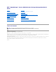
Back to Contents Page Supported Features Dell™ OpenManage™ Server Administrator Storage Management User's Guide Supported Features on the PERC 3/SC, 3/DC, 3/QC, 4/SC, 4/DC, 4/Di, 4e/Si, 4e/Di, 4e/DC, CERC ATA100/4ch, and 4/IM Controllers Supported Features on the PERC S100 and S300 Controllers Supported Features on the PERC 3/Si, 3/Di, CERC SATA1.5/2s, and CERC SATA1.
Start Patrol Read No No No No No No No No No No No Stop Patrol Read No No No No No No No No No No No Battery Tasks Table A-2.
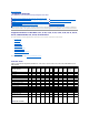
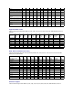
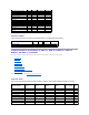
Virtual Disk Task Name PERC 3/SC PERC 3/DC PERC 3/QC PERC 4/SC PERC 4/DC PERC 4/DI PERC 4e/SI PERC 4e/DI PERC 4e/DC CERC ATA 100/4ch PERC 4/IM Assign and Unassign Dedicated Hot Spare Yes Yes Yes Yes Yes Yes Yes Yes Yes Yes No Create Virtual Disk Yes Yes Yes Yes Yes Yes Yes Yes Yes Yes No Create Virtual Disk Advanced Wizard Yes Yes Yes Yes Yes Yes Yes Yes Yes Yes No Create Virtual Disk Express Wizard Yes Yes Yes Yes Yes Yes Yes Yes Yes Yes No Rename
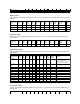
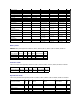
a RAID 0 Minimum Number of Physical Disks in a RAID 1 2 2 2 2 2 2 2 2 2 2 2 Minimum Number of Physical Disks in a RAID 5 3 3 3 3 3 3 3 3 3 3 NA Minimum Number of Physical Disks in a RAID 10 4 4 4 4 4 4 4 4 4 4 NA Minimum Number of Physical Disks in a RAID 50 6 6 6 6 6 6 6 6 6 NA NA Maximum number of physical disks in NA a RAID 6 NA NA NA NA NA NA NA NA NA NA Maximum number of physical disks in NA a RAID 60 NA NA NA NA NA NA NA NA NA NA Mi
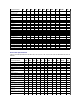
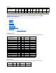
Controllers Enclosure Support PERC 3/SC PERC 3/DC PERC 3/QC PERC 4/SC PERC 4/DC PERC 4/DI PERC 4e/SI PERC 4e/DI PERC 4e/DC CERC ATA 100/4ch PERC 4/IM Can an enclosure be attached to this controller? Yes Yes Yes Yes Yes Yes Yes Yes Yes No No Supported Features on the PERC 3/Si, 3/Di, CERC SATA1.5/2s, and CERC SATA1.
Start Learn Cycle No No No No Delay Learn Cycle No No No No Connector Tasks Table A-12. Connector Tasks Supported by the PERC 3/Si, 3/Di, CERC SATA1.5/2s, and CERC SATA1.5/6ch Controllers Connector Task Name PERC 3/SI PERC 3/DI CERC SATA 2S CERC SATA 6ch Connector Rescan Yes Yes Yes Yes Physical Disk Tasks Table A-13. Physical Disk Tasks Supported by the PERC 3/Si, 3/Di, CERC SATA1.5/2s, and CERC SATA1.
Initialize Virtual Disk No No No No Fast Initialize Virtual Disk No No No No Slow Initialize Virtual Disk No No No No Cancel Initialize Virtual Disk No No No No Virtual Disk Specifications Table A-15. Virtual Disk Specifications for the PERC 3/Si, 3/Di, CERC SATA1.5/2s, and CERC SATA1.
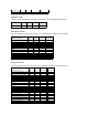
Read, Write, and Cache Policy PERC 3/SI PERC 3/DI CERC SATA 2S CERC SATA 6ch Cache settings Yes Yes No Yes Read Policy Yes Yes No Yes Read Ahead (Enabled) Yes Yes No Yes Adaptive Read Ahead No No No No No Read Ahead (Disabled) Yes Yes Yes Yes Write Policy Yes Yes No Yes Write Back (Enabled) No No No No Write Through (Disabled) Yes Yes Yes Yes Force Write Back (Enabled Always) No No No No Write Cache Enabled Protected Yes Yes No Yes Cache Policy No No No
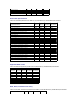
Rescan Controller No No No No No No Create Virtual Disk Yes Yes Yes Yes Yes Yes Export Log File Yes Yes Yes Yes Yes Yes Clear Foreign Configuration Yes Yes Yes Yes Yes Yes Import Foreign Configuration Yes Yes Yes Yes Yes Yes Import/Recover Foreign Configuration Yes with firmware 5.1.x or greater. Yes with firmware 5.1.x or greater.
Rebuild Yes Yes Yes Yes Yes Yes Cancel Rebuild Yes Yes Yes Yes Yes Yes Remove Dead Disk Segments No No No No No No Format Disk No No No No No No Clear Yes Yes Yes Yes Yes Yes Cancel Clear Yes Yes Yes Yes Yes Yes Cancel Replace Member No No Yes with firmware 6.1 and later Yes with firmware 6.1 and later Yes with firmware 6.1 and later No Virtual Disk Tasks Table A-23.
Maximum Number of Physical Disks that Can Be Concatenated NA NA NA NA NA NA Maximum Number of Physical Disks in a RAID 0 32 32 32 32 32 32 Maximum Physical Disks in a RAID 1 2 2 2 2 2 2 Maximum Number of Physical Disks in a RAID 5 32 32 32 32 32 32 Maximum Number of Physical Disks in a RAID 10 16 16 256 16 with firmware version 6.
Table A-27. Enclosure Support on the PERC 5/E, PERC 5/i, PERC 6/E, PERC 6/I, PERC 6/I, Modular, and CERC 6/I Controllers Enclosure Support PERC 5/E PERC 5/I PERC 6/E PERC 6/I PERC 6/I Modular CERC 6/I Can an enclosure be attached to this controller? Yes No Yes No No No Supported Features on the SAS 5/iR and SAS 6/iR Controllers This section identifies the controller-supported features and whether or not an enclosure can be attached to the controller.
Connector Tasks Table A-30. Connector Tasks Supported on the SAS 5/iR and SAS 6/iR Controllers Connector Task Name SAS 5/IR SAS 6/iR Connector Rescan No No Physical Disk Tasks Table A-31. Physical Disk Tasks Supported on the SAS 5/iR and SAS 6/iR Controllers Physical Disk Task Name SAS 5/IR SAS 6/iR Blink/Unblink Yes Yes Task only available when an enclosure or backplane and LEDs on the physical disks are present.
Resume Check Consistency No No Cancel Background Initialization (BGI) No No Format Virtual Disk No No Cancel Format Virtual Disk No No Restore Dead Disk Segments No No Initialize Virtual Disk No No Fast Initialize Virtual Disk No No Slow Initialize Virtual Disk No No Cancel Initialize Virtual Disk No No Supported RAID Levels Table A-33.
Cache settings No No Read Policy Yes Yes Read Ahead (Enabled) No No Adaptive Read Ahead No No No Read Ahead (Disabled) Yes Yes Write Policy Yes Yes Write Back No No Write Through Yes Yes Force Write Back (Enabled Always) No No Write Cache Enabled Protected No No Cache Policy No No Disk Cache Policy No No Cache I/O No No Direct I/O No No Enclosure Support Table A-36.
Table A-39.
Table A-42.
Create Virtual Disk No No Export Log File No No Clear Foreign Configuration No No Import Foreign Configuration No No Import/Recover Foreign Configuration No No Set Patrol Read Mode No No Start Patrol Read No No Stop Patrol Read No No Battery Tasks Table A-45. Battery Tasks Supported on the Non-RAID Controllers Battery Task Name Non-RAID SCSI Non-RAID SAS Recondition Battery No No Start Learn Cycle No No Delay Learn Cycle No No Connector Tasks Table A-46.
Create Virtual Disk Express Wizard No No Rename No No Blink/Unblink No No Reconfigure No No Change Policy No No Split Mirror No No Unmirror No No Delete Last Virtual Disk No No Delete (any) Virtual Disk No No Check Consistency No No Cancel Check Consistency No No Pause Check Consistency No No Resume Check Consistency No No Cancel Background Initialization (BGI) No No Format Virtual Disk No No Cancel Format Virtual Disk No No Restore Dead Disk Segments No No
Values Set Asset Data (includes asset tag and asset name) No No Yes Yes Yes Yes Blink Enclosure No No No No Yes Yes Enclosure and Backplane Support for Smart Thermal Shutdown Table A-51.
Back to Contents Page Determining the Health Status for Storage Components Dell™ OpenManage™ Server Administrator Storage Management User's Guide Health Status Rollup: Battery is Charging or Dead Health Status Rollup: Enclosure Power Supply Failed or Power Connection Removed Health Status Rollup: Physical Disks in a Virtual Disk are Failed or Removed Health Status Rollup: One Enclosure Fan is Failed Health Status Rollup: Physical Disks in a Virtual Disk are Unsupported, Partially or Perman
Storage Subsystem Controller Battery Connector Physical Disk(s) Firmware/ Virtual Disk(s) Driver Component Status Health Rollup Health Status Rollup: All Physical Disks in a Virtual Disk are in Foreign State Table B-4.
Storage Subsystem Controller Battery Connector Physical Disk(s) Firmware/Driver Virtual Disk(s) Component Status Health Rollup Health Status Rollup: Unsupported Firmware Version Table B-8.
Health Rollup NA Health Status Rollup: One Enclosure Temperature Probe is Failed Table B-12. Health Status Rollup: One Enclosure Temperature Probe is Failed Storage Subsystem Controller Connector Enclosure Enclosure Temperature Probe Virtual Disks Physical Disks Component Status Health Rollup NA Health Status Rollup: Lost Both Power Connections to the Enclosure Table B-13.
Health Status Rollup: Physical Disk is Rebuilding Table B-15.
Back to Contents Page Physical Disks Dell™ OpenManage™ Server Administrator Storage Management User's Guide Add a New Disk to Your System Assign and Unassign Global Hot Spare How to Avoid Removing the Wrong Disk Online and Offline Replacing a Physical Disk Receiving SMART Alerts Clear Physical Disk and Cancel Clear Other Disk Procedures Physical Disk Properties and Tasks Revertible Hot Spare Physical disks reside within an enclosure or are attached to the controller.
If the disk is part of a redundant virtual disk: 1. Select the redundant virtual disk that includes the physical disk that is receiving SMART alerts and perform the Check Consistency task. See "Check Consistency" for more information. CAUTION: To avoid potential data loss, you should perform a check consistency before removing a physical disk that is receiving SMART alerts.
Warning/Non-critical Critical/Fatal See "Storage Component Severity" for more information. Name This property displays the name of the physical disk. The name is comprised of the connector number followed by the disk number. State This property displays the current state of the physical disk. Ready — The physical disk is functioning normally. If the disk is attached to a RAID controller, Ready state indicates that the disk is available to be used by a virtual disk.
Bus Protocol This property displays the technology that the physical disk is using. Possible values are: SCSI — Small Computer System Interface SAS — Serial Attached SCSI SATA — Serial Advanced Technology Attachment (SATA) Media This property displays the media type of the physical disk. The possible values are: HDD—Hard Disk Drive. A HDD is a non-volatile storage device which stores digitally-encoded data on rapidly rotating platters with magnetic surfaces. SSD—Solid State Drive.
l "Prepare to Remove" l "Online and Offline" l "Initialize" l "Rebuild" l "Cancel Rebuild" l "Clear Physical Disk and Cancel Clear" l "Revertible Hot Spare" Blink and Unblink (Physical Disk) Does my controller support this feature? See "Supported Features." The Blink task allows you to find a disk within an enclosure by blinking one of the light-emitting diodes (LEDs) on the disk. You may want to use this task to locate a failed disk.
The Initialize task prepares a physical disk for use as a member of a virtual disk. Physical disks attached to PERC 3/Si, 3/Di, and CERC SATA1.5/6ch controllers must be initialized before they can be used. On these controllers, the Initialize task can only be performed once on a physical disk. In some cases a physical disk that is in an Unknown state can be returned to a usable state by performing the Initialize task.
Does my controller support this feature? See "Supported Features." The Online and Offline tasks only apply to physical disks that are included in a redundant virtual disk and attached to a PERC 3/SC, 3/DC, 3/QC,4/SC, 4/DC, 4e/Si, 4e/Di, 4e/DC, 4/Di, or CERC ATA100/4ch controller. Use the Offline task to deactivate a disk before removing it. Use the Online task to reactivate an offline disk. In some cases, you may want to use the Online task on a failed disk in an attempt to recover data from the disk.
5. Select the Physical Disks object. 6. Select Clear from the Available Tasks drop-down menu of the physical disk you want to clear. 7. Click Execute. Revertible Hot Spare Does my controller support this feature? See "Supported Features." Use the Revertible Hot Spare task to copy data back from a hot spare to a physical disk. If the physical disk in a virtual disk fails, the data on the failed disk is copied to the assigned hot spare.
Back to Contents Page RAID Controller Batteries Dell™ OpenManage™ Server Administrator Storage Management User's Guide Battery Properties and Tasks Some RAID controllers have batteries. If the controller has a battery, Storage Management displays the battery under the controller object in the tree view. In the event of a power outage, the controller battery preserves data that is in the nonvolatile cache memory (NVRAM) but not yet written to disk.
Degraded — The battery needs to be reconditioned. Reconditioning — The battery is being reconditioned. See "Recondition Battery" for more information. Charging — The battery is undergoing the recharge phase of the battery Learn cycle. See "Start Learn Cycle" for more information. Learning — The battery is undergoing the discharge phase of the battery Learn cycle. See "Start Learn Cycle" for more information. Missing — The controller is missing a battery.
l "Start Learn Cycle" l "Battery Delay Learn Cycle" Recondition Battery Does my controller support this feature? See "Supported Features." Some controllers have NiMHi batteries which need to be reconditioned approximately every six months to maintain reliability. This reconditioning cycle requires a full discharge and recharge of the battery. It ensures that the battery's capacity is being measured correctly and that the battery's full holdover time is maintained.
The controller firmware automatically initiates the battery Learn cycle every 90 days. Although you cannot stop the firmware from running the Learn cycle, you can delay the start time of the Learn cycle for up to seven days. See "Start Learn Cycle" for more information on the battery Learn cycle. To delay the battery Learn cycle: 1. Type a numerical value in the Days text box. The value must be within the 0 – 7 range.
Back to Contents Page BIOS Terminology Dell™ OpenManage™ Server Administrator Storage Management User's Guide BIOS Terms and the PERC 3/SC, 3/DC, 3/QC, 4/SC, 4/DC, 4e/DC, 4/Di, and CERC ATA100/4ch Controllers BIOS Terms and the PERC 3/Si, 3/Di, CERC SATA1.5/6ch, and CERC SATA1.5/2s Controllers The terminology used by Storage Management can be different from the terminology used in the controller BIOS. The following sections show some of these differences.
Back to Contents Page Connectors Dell™ OpenManage™ Server Administrator Storage Management User's Guide Channel Redundancy and Thermal Shutdown Channel Redundancy on PERC 3/DC, 3/QC, 4/DC, 4e/DC, 4/Di, and 4e/Di Controllers Creating a Channel-redundant Virtual Disk Connector Health Connector Properties and Tasks Logical Connector Properties and Tasks A controller contains one or more connectors (channels or ports) to which you can attach disks.
3. ¡ PERC 3/DC, 3/QC, 4/DC, 4e/DC, 4/Di, and 4e/Di Controllers: It is recommended that you only use RAID 10 or RAID 50. ¡ PERC 3/Di Controller: It is recommended that you only use RAID 10. Complete "Create Virtual Disk Advanced Wizard (Step 2 of 4)." In this step, you select the channels and the disks to be used by the virtual disk. The selections you make determine whether or not the virtual disk is channel-redundant.
The component may still be functioning, but it could fail. The component may also be functioning in an impaired state. Data loss is possible. Critical/Failure/Error. The component has either failed or failure is imminent. The component requires immediate attention and may need to be replaced. Data loss may have occurred.
Does my controller support this feature? See "Supported Features." On a SCSI controller, this task rescans the controller connectors to verify the currently connected devices or to recognize new devices that have been added to the connectors. Performing a rescan on a connector is similar to performing a rescan on the controller. For information on when you may want to do a rescan, see "Rescan to Update Storage Configuration Changes." NOTE: Rescan is not supported on non-RAID SCSI controllers.
Clearing the Redundant Path View If you do not want the redundant path view, physically disconnect the connector port from the enclosure and reboot the system. After the system reboots, the user interface will still display the Logical Connector, but in a critical state. If you are certain you do not want the redundant path mode, select Clear Redundant Path view from the Connector Tasks.
Back to Contents Page Command Line Interface Dell™ OpenManage™ Server Administrator Storage Management User's Guide CLI Command Syntax omconfig Virtual Disk Commands Syntax for Required, Optional, and Variable Command Elements omconfig Physical Disk Commands User Privileges for omreport storage and omconfig storage omconfig Battery Commands omreport Command omconfig Connector Commands omconfig Global Commands omconfig Enclosure Commands omconfig Controller Commands
pdisk= Parameter The omconfig syntax for specifying a physical disk includes the pdisk= parameter followed by the variable. How you specify the variable depends on whether the controller is using SCSI, SATA, ATA, or SAS technology. pdisk= Parameter on SAS Controllers On a SAS controller, the pdisk= parameter is specified as follows. See "SAS RAID Controllers" for a list of the controllers using SAS technology.
omconfig storage pdisk action=blink controller=1 pdisk=2:1,2:2,2:3 If controller 1 is a SAS controller, then to blink physical disks 1, 2, and 3 on enclosure 3 and connector 2 you would enter: omconfig storage pdisk action=blink controller=1 pdisk=2:3:1,2:3:2, 2:3:3 See "RAID Controller Technology: SCSI, SATA, ATA, and SAS" to identify which technology a controller uses. Syntax for Required, Optional, and Variable Command Elements The omreport and omconfig commands have multiple name=value pairs.
Required Command Levels (1, 2, 3) Use omreport storage -? Displays a list of storage components for which omreport commands are available. omreport storage pdisk - Displays a list of the omreport storage pdisk parameters for displaying physical disk information. See "omreport Physical Disk ? Status" for more information. omreport storage vdisk - Displays a list of the omreport storage vdisk parameters for displaying virtual disk information.
Required Command Levels (1, 2, 3) and name=value Pair Use omreport storage connector controller=id Displays all connectors on the specified controller. where id is the controller number. For example: controller=0 omreport storage connector controller=id connector=id Displays information for the specified connector on the controller. where id is the controller number.
where id is the controller number and is the enclosure ID and n is the number of a fan. Example for SCSI controllers: controller=0 enclosure=2 info=fans index=1. Example for SAS controllers: controller=0 enclosure=1:2 info=fans index=1. "enclosure= Parameter" for more information on specifying enclosures. omreport Power Supply Status Table 15-10.
connector=id Displays all physical disks attached to the specified connector on the controller. where id is the connector number. For example: connector=1 vdisk=id Displays all physical disks included in the specified virtual disk on the controller. where id is the virtual disk number. For example: vdisk=1 pdisk=connector:targetID Displays the specified physical disk on the specified connector on a SCSI, SATA, or ATA controller.
Example Syntax The omconfig command syntax for enabling thermal shutdown does not require that you specify a controller or enclosure ID. To enable thermal shutdown, enter the following: omconfig storage globalinfo action=enablests NOTE: You can use the omreport storage globalinfo command to determine whether smart thermal shutdown is currently enabled or disabled. The status of smart thermal shutdown is also displayed by the Server Administrator graphical user interface.
Use the following omconfig command syntax to set the Hot Spare Protection Policy for dedicated or global hot spares. See "Dedicated Hot Spare Protection Policy" and "Global Hot Spare Protection Policy" for more information.
Consistency Rate" omconfig storage vdisk action=exportlog controller=id "omconfig Export the Controller Log" action=importforeignconfig controller=id "omconfig Import Foreign Configuration" action=importrecoverforeignconfig controller=id "omconfig Import/Recover Foreign Configuration" action=clearforeignconfig controller=id "omconfig Clear Foreign Configuration" action=setpatrolreadmode controller=id mode=manual|auto|disable "omconfig Set Patrol Read Mode" action=startpatrolread controller=id
For example, to enable the alarm on controller 1, you would enter: omconfig storage controller action=enablealarm controller=1 omconfig Disable Controller Alarm Does my controller support this feature? See "Supported Features." Use the following omconfig command syntax to disable the controller alarm. See "Disable Alarm (Controller)" for more information.
omconfig storage controller action=testalarm controller=1 omconfig Reset Controller Configuration Does my controller support this feature? See "Supported Features." Use the following omconfig command syntax to reset the controller configuration. CAUTION: Resetting a configuration permanently destroys all data on all virtual disks attached to the controller. If the system or boot partition resides on these virtual disks, it will be destroyed.
Parameter Specification for Create and Reconfigure Virtual Disk The following sections indicate how to specify the omconfig storage controller action=createvdisk parameters.
PDISKID= Use this parameter to specify the physical disks that will be included in the virtual disk. When reconfiguring a virtual disk, you must specify all physical disks to be included in the reconfigured virtual disk. The physical disk specification applies to physical disks that were in the original virtual disk and will continue to be in the reconfigured virtual disk and to any new physical disks being added to the reconfigured virtual disk.
No write cache writepolicy=nwc Force write back writepolicy=fwb [name=] Parameter (Optional) Use this parameter to specify a name for the virtual disk. For example: name=VirtualDisk1 NOTE: The CERC SATA1.5/2s controller does not allow you to specify a virtual disk name. The virtual disk will be created with a default name.
Complete Syntax omconfig storage controller action=setrebuildrate controller=id rate=<0 to 100> where id is the controller ID as reported by the omreport storage controller command. Example Syntax For example, to set the rebuild rate on controller 1 to 50, you would enter: omconfig storage controller action=setrebuildrate controller=1 rate=50 omconfig Set Background Initialization Rate Does my controller support this feature? See "Supported Features.
Complete Syntax omconfig storage controller action=setcheckconsistency controller=id rate=<0 to 100> where id is the controller ID as reported by the omreport storage controller command. Example Syntax For example, to set the check consistency rate on controller 1 to 50, you would enter: omconfig storage controller action=setcheckconsistency controller=1 rate=50 omconfig Export the Controller Log Does my controller support this feature? See "Supported Features.
Does my controller support this feature? See "Supported Features." Use the following omconfig command syntax to import and recover all virtual disks that reside on physical disks newly attached to the controller. See "Foreign Configuration Operations" for more information. Complete Syntax omconfig storage controller action=importrecoverforeignconfig controller=id where id is the controller ID as reported by the omreport storage controller command.
Does my controller support this feature? See "Supported Features." Use the following omconfig command syntax to start the patrol read task on the controller. See "Start and Stop Patrol Read" for more information. NOTE: In order to start or stop the patrol read task, the patrol read mode should be set to Manual. See "Set Patrol Read Mode" for more information.
Does my controller support this feature? See "Supported Features." Use the following omconfig storage command syntax to replace a physical disk that is part of a virtual disk with another physical disk. See "Revertible Hot Spare" for more information.
action=slowinit controller=id vdisk=id "omconfig Slow Initialize Virtual Disk" action=cancelinitialize controller=id vdisk=id "omconfig Cancel Initialize Virtual Disk" action=cancelbginitialize controller=id vdisk=id "omconfig Cancel Background Initialize" action=restoresegments controller=id vdisk=id "omconfig Restore Dead Segments" action=splitmirror controller=id vdisk=id "omconfig Split Mirror" action=unmirror controller=id vdisk=id "omconfig Unmirror" action=assigndedicatedhotspare contr
Does my controller support this feature? See "Supported Features." Use the following omconfig command syntax to initialize a virtual disk. See "Format and Initialize; Slow and Fast Initialize" for more information. Complete Syntax omconfig storage vdisk action=initialize controller=id vdisk=id where id is the controller ID and virtual disk ID as reported by the omreport command.
Does my controller support this feature? See "Supported Features." Use the following omconfig command syntax to cancel the initialization of a virtual disk. Complete Syntax omconfig storage vdisk action=cancelinitialize controller=id vdisk=id where id is the controller ID and virtual disk ID as reported by the omreport command.
Does my controller support this feature? See "Supported Features." Use the following omconfig command syntax to separate mirrored data originally configured as a RAID 1, RAID 1-concatenated, or RAID 10 virtual disk. Splitting a RAID 1 or RAID 1-concatenated mirror creates two concatenated nonredundant virtual disks. Splitting a RAID 10 mirror creates two RAID 0 (striped) nonredundant virtual disks. Data is not lost during this operation. See "Split Mirror" for more information.
Example Syntax In this example, you are assigning physical disk 3 on connector 0 of controller 1 as a dedicated hot spare to virtual disk 4. On a SAS controller, the physical disk resides in enclosure 2.
Does my controller support this feature? See "Supported Features." Use the following omconfig command syntax to initiate a check consistency on a virtual disk. The check consistency task verifies the virtual disk's redundant data. Complete Syntax omconfig storage vdisk action=checkconsistency controller=id vdisk=id where id is the controller ID and virtual disk ID as reported by the omreport command.
Does my controller support this feature? See "Supported Features." Use the following omconfig command syntax to resume a check consistency after it has been paused. Complete Syntax omconfig storage vdisk action=resumecheckconsistency controller=id vdisk=id where id is the controller ID and virtual disk ID as reported by the omreport command.
For example, to format virtual disk 4 on controller 1, you would enter: omconfig storage vdisk action=format controller=1 vdisk=4 omconfig Reconfiguring Virtual Disks Does my controller support this feature? See "Supported Features." You can reconfigure a virtual disk in order to change the virtual disk's RAID level or increase its size by adding physical disks. On some controllers, you can also remove physical disks.
l "[readpolicy=] Parameter (Optional)" l "[writepolicy=] Parameter (Optional)" l "[cachepolicy=] Parameter (Optional)" l "[diskcachepolicy=] Parameter (Optional)" Example Syntax For example, to change the read policy of virtual disk 4 on controller 1 to no-read-ahead, you would enter: omconfig storage vdisk action=changepolicy controller=1 vdisk=4 readpolicy=nra omconfig Rename Virtual Disk Does my controller
omconfig Blink Physical Disk Does my controller support this feature? See "Supported Features." You can blink the light (light emitting diode or LED display) on one or more physical disks attached to a controller. Use the following omconfig command syntax to blink one or more physical disks. Complete Syntax omconfig storage pdisk action=blink controller=id pdisk= where id is the controller ID. The variable specifies the physical disk.
omconfig storage pdisk action=unblink controller=1 pdisk=0:2 See "pdisk= Parameter on SCSI, SATA, and ATA Controllers" and "Multiple Targets" for more information on physical disk specification. See "RAID Controller Technology: SCSI, SATA, ATA, and SAS" to identify which technology a controller uses.
To obtain these values, you would enter omreport storage controller to display the controller IDs and then enter omreport storage pdisk controller=ID to display the IDs for the physical disks attached to the controller. Example Syntax In this example, you want to initialize physical disk 3 on connector 0 of controller 1. On a SAS controller, the physical disk resides in enclosure 2.
omconfig Online Physical Disk Does my controller support this feature? See "Supported Features." Use the following omconfig command syntax to bring an offline physical disk back online. Complete Syntax omconfig storage pdisk action=online controller=id pdisk= where id is the controller ID. The variable specifies the physical disk. See "pdisk= Parameter" for more information.
Example for SCSI, SATA, and ATA Controllers: To assign the physical disk described in this example as a global hot spare, you would enter: omconfig storage pdisk action=assignglobalhotspare controller=1 pdisk=0:3 assign=yes See "pdisk= Parameter on SCSI, SATA, and ATA Controllers" and "Multiple Targets" for more information on physical disk specification. See "RAID Controller Technology: SCSI, SATA, ATA, and SAS" to identify which technology a controller uses.
Complete Syntax omconfig storage pdisk action=rebuild controller=id pdisk= where id is the controller ID. The variable specifies the physical disk. See "pdisk= Parameter" for more information. To obtain these values, you would enter omreport storage controller to display the controller IDs and then enter omreport storage pdisk controller=ID to display the IDs for the physical disks attached to the controller.
omconfig storage pdisk action=cancelrebuild controller=1 pdisk=0:2:3 See "pdisk= Parameter on SAS Controllers" and "Multiple Targets" for more information on physical disk specification. See "SAS RAID Controllers" to identify which controllers use SAS technology. omconfig Remove Dead Segments Does my controller support this feature? See "Supported Features." Use the following omconfig command syntax to recover unusable disk space. See "Remove Dead Segments" for more information.
omconfig storage pdisk action=clear controller=1 pdisk=0:2:3 See "pdisk= Parameter on SAS Controllers" and "Multiple Targets" for more information on physical disk specification. See "SAS RAID Controllers" to identify which controllers use SAS technology. omconfig Cancel Clear Physical Disk Does my controller support this feature? See "Supported Features." Use the following omconfig command to cancel a clear operation that is in progress on a physical disk.
action=delaylearn controller=id battery=id days=d hours=h "omconfig Delay Battery Learn Cycle" omconfig Recondition Battery Does my controller support this feature? See "Supported Features." Use the following omconfig command to recondition a controller battery. For more information on batteries and the recondition process, see "RAID Controller Batteries" and "Recondition Battery.
For example, to delay the learn cycle for three days and 12 hours on controller 1, you would enter: omconfig storage battery action=delaylearn controller=1 battery=0 days=3 hours=12 omconfig Connector Commands The following sections provide the omconfig command syntax required to execute connector tasks. Table 15-19.
omconfig Enable Enclosure Alarm Does my enclosure support this feature? See "Supported Features." Use the following omconfig command syntax to enable the enclosure alarm: Complete Syntax omconfig storage enclosure action=enablealarm controller=id enclosure= where id is the controller ID. The variable specifies the enclosure. See "enclosure= Parameter" for more information.
Does my enclosure support this feature? See "Supported Features." Use the following omconfig command syntax to specify the enclosure's asset tag: Complete Syntax omconfig storage enclosure action=setassettag controller=id enclosure= assettag= where id is the controller ID. The variable specifies the enclosure. See "enclosure= Parameter" for more information. In this syntax, is a user-specified alphanumeric string.
omconfig Set Temperature Probe Thresholds Does my enclosure support this feature? See "Supported Features." Use the following omconfig command syntax to set the minimum and maximum warning temperature thresholds for a specified temperature probe. Complete Syntax omconfig storage enclosure action=settempprobes controller=id enclosure= index=id minwarn=n maxwarn=n where id is the controller ID and the temperature probe ID. The variable specifies the enclosure.
Example for SAS Controllers: In this example, the temperature probes reside in enclosure 3 attached to connector 0 on controller 1. To set the thresholds for all temperature probes to 10 Celsius and 40, you would enter: omconfig storage enclosure action=setalltempprobes controller=1 enclosure=0:3 minwarn=10 maxwarn=40 See "enclosure= Parameter on SAS Controllers" for more information on enclosure specification.
omconfig storage enclosure action=blink controller=1 enclosure=0:3 See "enclosure= Parameter on SAS Controllers" for more information on enclosure specification. See "RAID Controller Technology: SCSI, SATA, ATA, and SAS" to identify which technology a controller uses.
Back to Contents Page Controllers Dell™ OpenManage™ Server Administrator Storage Management User's Guide What is a Controller? Reset Configuration RAID Controller Technology: SCSI, SATA, ATA, and SAS Export Log RAID Controller Features Foreign Configuration Operations Controller-supported RAID Levels Importing Foreign Configurations Controller-supported Stripe Sizes RAID Controller Read, Write, Cache, and Disk Cache Policy Cluster-enabled RAID Controllers Importing/Recov
l CERC ATA100/4ch l CERC 6/I controller family SAS RAID Controllers The following RAID controllers use Serial Attached SCSI (SAS) technology. l PERC 5/E l PERC 5/i Integrated l PERC 5/i Adapter l SAS 5/iR Integrated l SAS 5/iR Adapter l PERC 6/E l PERC 6/I controller family l SAS 6/iR controller family l PERC S100 and S300 controllers RAID Controller Features Different controllers have different features.
When creating a virtual disk, you specify the read, write, and cache policies for the virtual disk. The following sub-section describes these policies. NOTE: Read, write, and cache policies are not supported on the CERC SATA1.5/2s controller. Read Policy Does my controller support this feature? See "Supported Features." The read policies indicate whether or not the controller should read sequential sectors of the virtual disk when seeking data. l Read-Ahead.
The Direct I/O and Cache I/O cache policies apply to reads on a specific virtual disk. These settings do not affect the read-ahead policy. The cache policies are as follows: l Cache I/O. Specifies that all reads are buffered in cache memory. l Direct I/O. Specifies that reads are not buffered in cache memory. When using direct I/O, data is transferred to the controller cache and the host system simultaneously during a read request.
creating or deleting the virtual disk. The following procedure describes the sequence of actions required to create or delete a virtual disk from a clusterenabled controller. For the purposes of this procedure, the system on which you are creating or deleting the virtual disk is identified as system A and the other system in the cluster is identified as system B. NOTE: When creating a virtual disk on a controller that is in a cluster configuration, you must specify the maximum virtual disk size. 1.
l SAS 5/E Firmware/Driver Versions Use this window to view information about the controller firmware and drivers. For more information on firmware and drivers, see "Installation Considerations for Storage Management." Firmware/Driver Properties The firmware and driver properties can vary depending on the model of the controller. On some controllers, Storage Management may not be able to obtain the driver or firmware version. In this case, Storage Management displays Not Applicable.
Controller Information For information on the controller, see the following topics: l "Controllers" l "Controller Properties and Tasks" Controller Components For information on attached components, see the following topics: l "RAID Controller Batteries" l "Firmware/Driver Versions" l "Connectors" NOTE: If you have connected the enclosure in Redundant path mode, the connectors are represented as Logical Connector.
The 2.8.0.6085 driver install package for the PERC 3/Si, and 3/Di controllers contains the 6076 driver. For this driver, Storage Management displays 2.8.0.6076 whereas Microsoft® Windows® Device Manager displays 2.8.0.6085. NOTE: On some controllers, Storage Management may not be able to obtain the driver version. In this case, Storage Management displays Not Applicable. Minimum Required Driver Version This property displays the minimum driver version that is required by Storage Management.
Controller Tasks Do the following to execute a controller task: 1. Expand the Storage tree object to display the controller objects. 2. Select a controller object. 3. Select the Information/Configuration subtab. 4. Select a task from the Available Tasks drop-down menu. 5. Click Execute. NOTE: Different controllers support different features. For this reason, the tasks displayed on the Tasks drop-down menu can vary depending on which controller is selected in the tree view.
3. Click the Configuration/Information subtab. 4. Select Rescan from the Controller Tasks drop-down menu. 5. Click Execute. You can also locate this task from the Change Controller Properties drop down menu. For more information, see "Change Controller Properties." Create Virtual Disk Does my controller support this feature? See "Supported Features." Use the Create Virtual Disk task to launch the Create Virtual Disk Express Wizard.
Controller Components For information on attached components, see the following topics: l "Battery Properties and Tasks" l "Connector Properties and Tasks" l "Enclosure and Backplane Properties and Tasks" l "Firmware/Driver Properties" l "Virtual Disk Properties and Tasks" Foreign Configuration Operations Does my controller support this feature? See "Supported Features." The Foreign Configuration Operations task provides a preview of the foreign configurations that you can import.
Reset Configuration Does my controller support this feature? See "Supported Features." Use the Reset Configuration task to erase all information on the controller so that you can perform a fresh configuration. This operation destroys all data and virtual disks on the controller and unassigns any hot spares. You will need to completely reconfigure your storage after performing this operation.
2. Select a controller object. 3. Select the Information/Configuration subtab. 4. Select Export Log from the Available Tasks drop-down menu. 5. Click Execute. You can also locate this task from the Change Controller Properties drop down menu. For more information, see "Change Controller Properties." Foreign Configuration Operations NOTE: Foreign Configuration Operations is available only on SAS controllers with firmware versions 6.1 and later.
l l l l l Dedicated Hot Spare Missing physical disk or missing span — One or more physical disks or spans in the virtual disk to be imported is missing. Unsupported — The selected RAID level is not supported on this controller. Orphan Drive — The physical disk was once part of a RAID volume but was replaced. The configuration should be cleared. Stale Physical Disk — The physical disk in the virtual disk to be imported has outdated data.
To locate this task in Storage Management: For SAS controllers with firmware versions 6.1 and later: 1. Expand the Storage tree object to display the controller objects. 2. Select a controller object. 3. Select the Information/Configuration subtab. 4. Select Foreign Configuration Operations from the Controller Available Tasks drop-down menu. 5. Click Execute. 6. On the Foreign Configuration Preview page, click Import/Recover. For controllers with firmware version 6.
5. Click Execute. 6. On the Foreign Configuration Preview page, click Clear. For controllers with firmware version 6.0 and earlier: 1. Expand the Storage tree object to display the controller objects. 2. Select a controller object. 3. Select the Information/Configuration subtab. 4. Select Clear Foreign Configuration from the Controller tasks.
"2109" "2110" "2111" Progress This property displays the progress of an operation being performed on the physical disk. For example, if the physical disk is being rebuilt, then a value of 52% indicates that the rebuild is 52% complete. This property is only displayed when an operation is being performed on the physical disk. Bus Protocol This property displays the technology that the physical disk is using.
be the setting with the least impact to system performance. A background initialization rate of 0% does not mean that the background initialization is stopped or paused. At 100%, the background initialization will be the highest priority for the controller, will minimize the background initialization time, and will be the setting with the most impact to system performance. To change the controller's background initialization rate: 1.
Related Information: l "Check Consistency" l "Cancel Check Consistency" Set Reconstruct Rate Does my controller support this feature? See "Supported Features." The Set Reconstruct Rate task changes the amount of system resources dedicated to the reconstruct task. The reconstruct task remakes the virtual disk after you have changed the RAID level or otherwise reconfigured the virtual disk.
If the communication channel between the connector and the first enclosure is lost, the redundant path configuration itself is lost. In this case, the health of the logical connector is displayed as critical. Navigate to the Information/Configuration subtab of the logical connector to view details of the "Path Health." See the table below for a brief outline of this scenario.
l "Logical Connector Properties and Tasks" l "Enclosure and Backplane Properties and Tasks" Set Patrol Read Mode Does my controller support this feature? See "Supported Features." Patrol Read is a feature for identifying disk errors in order to avoid disk failures and data loss or corruption. The Patrol Read only runs on disks that are being used in a virtual disk or that are hot spares. When possible, the Patrol Read corrects disk errors and restores the integrity of the data.
Start and Stop Patrol Read Does my controller support this feature? See "Supported Features." When the Patrol Read mode is set to manual, you can start the Patrol Read task or stop the task when it is running. There are certain conditions under which the Patrol Read task cannot be run. See "Set Patrol Read Mode" for more information. To start or stop the Patrol Read task: Click Start Patrol Read or Stop Patrol Read when ready.
3. Click Execute. Or: 1. Expand the Storage tree object to display the controller objects. 2. Select a controller object. 3. Select the Information/Configuration subtab. 4. Select Change Controller Properties... from the Controller Tasks drop down menu. 5. Click Execute.
Back to Contents Page Enclosures and Backplanes Dell™ OpenManage™ Server Administrator Storage Management User's Guide Backplanes Set Asset Data Enclosures Set Temperature Probe Values SMART Thermal Shutdown EMM Properties Changing the Mode on PowerVault 220S and PowerVault 221S Enclosures Fan Properties Enclosure Management Power Supply Properties Enclosure and Backplane Health Enclosure and Backplane Properties and Tasks Temperature Probe Properties and Tasks
Enclosure Power Supplies The enclosure's power supplies are displayed under the Power Supplies object in the tree view. You can select the Power Supplies object to display their status information. Enclosure Temperature Probes The enclosure's temperature probes are displayed under the Temperatures object. You can select the Temperatures object to display their status information.
Changing the Mode on PowerVault 220S and PowerVault 221S Enclosures When toggling the bus configuration switch on a PowerVault 220S or PowerVault 221S enclosure, the enclosure should be powered off. The bus configuration switch is used to change the enclosure to split bus, joined bus, or clustered mode. If you change the PowerVault 220S or PowerVault 221S enclosure mode with the enclosure powered on, the enclosure may no longer be displayed by Storage Management and you may notice other erratic behaviors.
l "Physical Disks" Enclosure and Backplane Properties and Tasks Use this window to view information about the enclosure or backplane and execute enclosure tasks. Enclosure and Backplane Properties The enclosure or backplane properties can vary depending on the model of the controller. Enclosure or backplane properties may include: Property Definition These icons represent the severity or health of the storage component. See "Storage Component Severity" for more information.
Enclosure Alarm This property displays whether the enclosure's alarm is enabled or disabled. Enclosure Tasks Do the following to execute a drop-down menu enclosure task: 1. Expand the Storage tree object to display the controller objects. 2. Expand a controller object. 3. Expand a Connector object. 4. Select the enclosure object. 5. Select the Information/Configuration subtab. 6. Select a task from the Available Tasks drop-down menu. 7. Click Execute.
Does my enclosure support this feature? See "Supported Features." Use the Blink task to blink the light-emitting diodes (LEDs) on the enclosure. You may want to use this task to locate an enclosure. The LEDs on the enclosure may display different colors and blinking patterns. Refer to the enclosure hardware documentation for more information on what the blink colors and patterns indicate. Set Temperature Probe Value Does my enclosure support this feature? See "Supported Features.
Enclosure Components For information on attached components, see the following topics: l "Physical Disk Properties and Tasks" l "EMM Properties" l "Fan Properties" l "Power Supply Properties" l "Temperature Probe Properties and Tasks" Set Asset Data Does my enclosure support this feature? See "Supported Features." You can change the enclosure's asset tag and asset name. The new asset tag and asset name that you specify are displayed on the enclosure's Information/Configuration subtab.
Select Set new values in the Set New Temperature Probe Values section of the screen. 2. 3. Type the lowest acceptable temperature in Celsius for the enclosure in the Minimum Warning Threshold text box. The text box label indicates the range that you can specify. 4. Type the highest acceptable temperature in Celsius for the enclosure in the Maximum Warning Threshold text box. The text box label indicates the range that you can specify. Click Apply Changes. 5.
SCSI SES Module — A SCSI SES Module provides SES and SAFTE reporting to the host server, control of all system LED indicators, and monitoring of all environmental elements, such as temperature sensors, cooling modules, and power supplies. SCSI Terminator — The SCSI Terminator card is only used if the PowerVault™ 220S or PowerVault 221S enclosure is not configured with a redundant SCSI SES Module type of EMM. In systems equipped with two SCSI SES Modules, the SCSI termination is done through the EMMs.
See "Storage Component Severity" for more information. Name This property displays the name of the power supply. State This property displays the current status of the power supply. Ready — The power supply is functioning normally. Degraded — The power supply has encountered a failure and is operating in a degraded state. Failed — The power supply has encountered a failure and is no longer functioning. Storage Management may also be unable to communicate with the enclosure using SES commands.
Click the Set Temperature Probe button to launch the wizard for changing the temperature probe's Warning threshold. You can change the Warning threshold for each of the temperature probes included in the enclosure. See "Set Temperature Probe Values" for more information. Do the following to launch the Set Temperature Probe wizard: 1. Expand the Storage tree object to display the controller objects. 2. Expand a controller object. 3. Expand a Connector object. 4. Expand the enclosure object.
Back to Contents Page Alert Messages Dell™ OpenManage™ Server Administrator Storage Management User's Guide Alert Monitoring and Logging Viewing Alerts Alert Severity Levels Alert Message Format with Substitution Variables Configuring an Automated Response to Alerts SNMP Support for Storage Management Alerts Alert Descriptions and Corrective Actions Storage Management's alert or event management features let you monitor the health of storage resources such as controllers, enclosures, physi
Warning/Noncritical. A component requires attention. This alert indicates a potential problem, but does not necessarily mean that the system has currently lost data or is nonfunctional. For example, a Warning/Noncritical alert may indicate that a component (such as a temperature probe in an enclosure) has crossed a warning threshold. Critical/Failure/Error. A component has either failed or failure is imminent. This alert indicates a serious problem such as data loss or a loss of function.
SCSI Power Supply Message Format: Power Supply X Controller A, Connector B, Target ID where Target ID refers to the SCSI ID of the SCSI processor device (EMM) managing the power supply. Example: 2122 Redundancy degraded: Power Supply 1, Controller 1, Connector 0, Target ID 6 SAS Power Supply Message Format: Power Supply X Controller A, Connector B, Enclosure C Example: 2312 A power supply in the enclosure has an AC failure.
information on configuring an application to receive SNMP traps, refer to the documentation for that application. SNMP Trap Definitions The Storage Management management information base (MIB) defines the SNMP traps that Storage Management generates. These traps correspond to the alerts documented in "Alert Descriptions and Corrective Actions." The MIB is located in a subdirectory of the Storage Management installation directory. The subdirectory location for the MIB is ..\sm\mibs\dcstorag.mib.
Local Response Agent (LRA) Alert Number: 2070 SNMP Trap Number: 903. See "SNMP Support for Storage Management Alerts" for more information. 2050 Description: Physical disk offline Cause: A physical disk in the disk group is offline. A user may have manually put the physical disk offline. Action: Perform a rescan. You can also select the offline disk and perform a Make Online operation. Severity: Warning/Noncritical. See "Alert Severity Levels" for more information. Clear Alert Number: 2158.
Action: None. Severity: OK/Normal/Informational. See "Alert Severity Levels" for more information. Clear Alert Number: None. Related Alert Number: None. Local Response Agent (LRA) Alert Number: None. SNMP Trap Number: 1201. See "SNMP Support for Storage Management Alerts" for more information. 2054 Description: Virtual disk deleted Cause: A virtual disk has been deleted. Performing a Reset Configuration may detect that a virtual disk has been deleted and generate this alert. Action: None.
Description: Virtual disk degraded Cause 1: This alert message occurs when a physical disk included in a redundant virtual disk fails. Because the virtual disk is redundant (uses mirrored or parity information) and only one physical disk has failed, the virtual disk can be rebuilt. Action 1: Configure a hot spare for the virtual disk if one is not already configured. Rebuild the virtual disk.
Severity: OK/Normal/Informational. See "Alert Severity Levels" for more information. Clear Alert Number: None. Related Alert Number: 2075. Local Response Agent (LRA) Alert Number: None. SNMP Trap Number: 901. See "SNMP Support for Storage Management Alerts" for more information. 2061 Description: Virtual disk initialization started Cause: This alert is provided for informational purposes. Action: None. Severity: OK/Normal/Informational. See "Alert Severity Levels" for more information.
Description: Virtual disk rebuild started Cause: This alert is provided for informational purposes. Action: None. Severity: OK/Normal/Informational. See "Alert Severity Levels" for more information. Clear Alert Number: 2091. The clear alert is generated when the conditions producing the current alert have returned to normal. Related Alert Number: None. Local Response Agent (LRA) Alert Number: None. SNMP Trap Number: 1201. See "SNMP Support for Storage Management Alerts" for more information.
SNMP Trap Number: 1201. See "SNMP Support for Storage Management Alerts" for more information. 2074 Description: Physical disk rebuild cancelled Cause: A user has cancelled the rebuild operation. Action: Restart the rebuild operation. Severity: OK/Normal/Informational. See "Alert Severity Levels" for more information. Clear Alert Number: None. Related Alert Number: None. Local Response Agent (LRA) Alert Number: None. SNMP Trap Number: 901.
Severity: Critical/Failure/Error. See "Alert Severity Levels" for more information. Clear Alert Number: None. Related Alert Number: None. Local Response Agent (LRA) Alert Number: 2081 SNMP Trap Number: 1204. See "SNMP Support for Storage Management Alerts" for more information. 2079 Description: Virtual disk initialization failed Cause: The controller cannot communicate with attached devices. A disk may be removed or contain errors. Cables may also be loose or defective.
Description: Virtual disk rebuild failed Cause: A physical disk included in the virtual disk has failed or is corrupt. A user may also have cancelled the rebuild. Action: Replace the failed or corrupt disk. You can identify a disk that has failed by locating the disk that has a red X for its status. Restart the virtual disk rebuild. Severity: Critical/Failure/Error. See "Alert Severity Levels" for more information. Clear Alert Number: None.
Local Response Agent (LRA) Alert Number: None. SNMP Trap Number: 1201. See "SNMP Support for Storage Management Alerts" for more information. 2087 Description: Copy of data resumed from physical disk %2 to physical disk %1 Cause: This alert is provided for informational purposes. Action: None. Severity: OK/Normal/Informational. See "Alert Severity Levels" for more information. Clear Alert Status: None. Related Alert Number: 260. Local Response Agent (LRA) Alert Number: None. SNMP Trap Number: 901.
Severity: OK/Normal/Informational. See "Alert Severity Levels" for more information. Clear Alert Status: Alert 2090 is a clear alert for alert 2063. Related Alert Number: None. Local Response Agent (LRA) Alert Number: None. SNMP Trap Number: 1201. See "SNMP Support for Storage Management Alerts" for more information. 2091 Description: Virtual disk rebuild completed Cause: This alert is provided for informational purposes. Action: None. Severity: OK/Normal/Informational.
SNMP Trap Number: 903. See "SNMP Support for Storage Management Alerts" for more information. 2095 Description: SCSI sense data %1. Cause: A SCSI device experienced an error, but may have recovered. The %1 indicates a substitution variable. The text for this substitution variable is displayed with the alert in the Alert Log and can vary depending on the situation. Action: None. Severity: OK/Normal/Informational. See "Alert Severity Levels" for more information. Clear Alert Number: None.
Description: Temperature exceeded the maximum warning threshold. Cause: The physical disk enclosure is too hot. A variety of factors can cause the excessive temperature. For example, a fan may have failed, the thermostat may be set too high, or the room temperature may be too hot. Action: Check for factors that may cause overheating. For example, verify that the enclosure fan is working. You should also check the thermostat settings and examine whether the enclosure is located near a heat source.
Local Response Agent (LRA) Alert Number: 2091 SNMP Trap Number: 1054. See "SNMP Support for Storage Management Alerts" for more information. 2104 Description: Controller battery is reconditioning. Cause: This alert is provided for informational purposes. Action: None. Severity: OK/Normal/Informational. See "Alert Severity Levels" for more information. Clear Alert Number: 2105. The clear alert is generated when the conditions producing the current alert have returned to normal.
Cause: A disk has received a SMART alert (predictive failure) after a configuration change. The disk is likely to fail in the near future. Action: Replace the disk that has received the SMART alert. If the physical disk is a member of a nonredundant virtual disk, ensure that you back up the data before replacing the disk. CAUTION: Removing a physical disk that is included in a nonredundant virtual disk will cause the virtual disk to fail and may cause data loss. Severity: Critical/Failure/Error.
Description: SMART warning degraded. Cause: A disk is degraded and has received a SMART alert (predictive failure). The disk is likely to fail in the near future. Action: Replace the disk that has received the SMART alert. If the physical disk is a member of a nonredundant virtual disk, ensure that you back up the data before replacing the disk. CAUTION: Removing a physical disk that is included in a nonredundant virtual disk will cause the virtual disk to fail and may cause data loss.
Related Alert Number: None. Local Response Agent (LRA) Alert Number: None. SNMP Trap Number: 1201. See "SNMP Support for Storage Management Alerts" for more information. 2115 Description: A Check Consistency on a virtual disk has been resumed. Cause: This alert is provided for informational purposes. The check consistency operation on a virtual disk has resumed processing after being paused by a user. Action: None. Severity: OK/Normal/Informational. See "Alert Severity Levels" for more information.
Description: The write policy has changed. Cause: This alert is provided for informational purposes. A user has changed the write policy for a virtual disk. Action: None. Severity: OK/Normal/Informational. See "Alert Severity Levels" for more information. Clear Alert Number: None. Related Alert Number: None. Local Response Agent (LRA) Alert Number: None. SNMP Trap Number: 1201. See "SNMP Support for Storage Management Alerts" for more information.
Local Response Agent (LRA) Alert Number: 2090 SNMP Trap Number: 1305. See "SNMP Support for Storage Management Alerts" for more information. 2123 Description: Redundancy lost Cause: A virtual disk or an enclosure has lost data redundancy. In the case of a virtual disk, one or more physical disks included in the virtual disk have failed. Due to the failed physical disk or disks, the virtual disk is no longer maintaining redundant (mirrored or parity) data.
Description: SCSI sense sector reassign Cause: A sector of the physical disk is corrupted and data cannot be maintained on this portion of the disk. This alert is provided for informational purposes. CAUTION: Any data residing on the corrupt portion of the disk may be lost and you may need to restore your data from backup. Action: If the physical disk is part of a nonredundant virtual disk, ensure that you back up the data and replace the physical disk.
Clear Alert Number: None. Related Alert Number: 2340 Local Response Agent (LRA) Alert Number: 2081 SNMP Trap Number: 1204. See "SNMP Support for Storage Management Alerts" for more information. 2130 Description: Background initialization completed Cause: Background initialization of a virtual disk has completed. This alert is provided for informational purposes. Action: None. Severity: OK/Normal/Informational. See "Alert Severity Levels" for more information.
Description: Array Manager is installed on the system Cause: Storage Management has been installed on a system that has an Array Manager installation. Action: Installing Storage Management and Array Manager on the same system is not a supported configuration. Uninstall either Storage Management or Array Manager. Severity: Warning/Noncritical. See "Alert Severity Levels" for more information. Clear Alert Number: None. Related Alert Number: None.
Severity: OK/Normal/Informational. See "Alert Severity Levels" for more information. Clear Alert Number: None. Related Alert Number: None. Local Response Agent (LRA) Alert Number: None. SNMP Trap Number: 851. See "SNMP Support for Storage Management Alerts" for more information. 2139 Description: Enclosure alarm disabled Cause: A user has disabled the enclosure alarm. Action: None. Severity: OK/Normal/Informational. See "Alert Severity Levels" for more information. Clear Alert Number: None.
Description: Controller rebuild rate has changed Cause: A user has changed the controller rebuild rate. This alert is provided for informational purposes. Action: None. Severity: OK/Normal/Informational. See "Alert Severity Levels" for more information. Clear Alert Number: None. Related Alert Number: None. Local Response Agent (LRA) Alert Number: None. SNMP Trap Number: 751. See "SNMP Support for Storage Management Alerts" for more information.
2146 Description: Bad block replacement error Cause: A portion of a physical disk is damaged. See "Receive a "Bad Block" Alert with "Replacement," "Sense," or "Medium" Error" for more information. Action: See "Receive a "Bad Block" Alert with "Replacement," "Sense," or "Medium" Error" for more information. Severity: Warning/Noncritical. See "Alert Severity Levels" for more information. Clear Alert Number: None. Related Alert Number: None.
Related Alert Number: None. Local Response Agent (LRA) Alert Number: 2060 SNMP Trap Number: 753. See "SNMP Support for Storage Management Alerts" for more information. 2150 Description: Bad block extended medium error Cause: A portion of a physical disk is damaged. See "Receive a "Bad Block" Alert with "Replacement," "Sense," or "Medium" Error" for more information. Action: See "Receive a "Bad Block" Alert with "Replacement," "Sense," or "Medium" Error" for more information.
Action: Ensure that the service tag was changed under authorized circumstances. Severity: OK/Normal/Informational. See "Alert Severity Levels" for more information. Clear Alert Number: None. Related Alert Number: None. Local Response Agent (LRA) Alert Number: None. SNMP Trap Number: 851. See "SNMP Support for Storage Management Alerts" for more information.
Description: Controller configuration has been reset. Cause: A user has reset the controller configuration. See "Reset Configuration" for more information. This alert is provided for informational purposes. Action: None. Severity: OK/Normal/Informational. See "Alert Severity Levels" for more information. Clear Alert Number: None. Related Alert Number: None. Local Response Agent (LRA) Alert Number: None. SNMP Trap Number: 751. See "SNMP Support for Storage Management Alerts" for more information.
Local Response Agent (LRA) Alert Number: None. SNMP Trap Number: 851. See "SNMP Support for Storage Management Alerts" for more information. 2163 Description: Rebuild completed with errors Cause: See "A Rebuild Completes with Errors" for more information. Action: See "A Rebuild Completes with Errors" for more information. Severity: Critical/Failure/Error. See "Alert Severity Levels" for more information. Clear Alert Number: None. Related Alert Number: None.
Cause: Storage Management is unable to determine whether the system has the minimum required versions of the RAID controller firmware and drivers. This situation has occurred because a configuration file is unreadable or missing data. The configuration file may be corrupted. Action: Reinstall Storage Management. Severity: Warning/Noncritical. See "Alert Severity Levels" for more information. Clear Alert Number: None. Related Alert Number: None.
SNMP Trap Number: 1154. See "SNMP Support for Storage Management Alerts" for more information. 2170 Description: The controller battery charge level is normal. Cause: This alert is provided for informational purposes. Action: None. Severity: OK/Normal/Informational. See "Alert Severity Levels" for more information. Clear Alert Number: None. Related Alert Number: None. Local Response Agent (LRA) Alert Number: None. SNMP Trap Number: 1151.
Action: Replace one or more EMMs so that all EMMs in the enclosure have the same SCSI rate. Severity: Warning/Noncritical. See "Alert Severity Levels" for more information. Clear Alert Number: None. Related Alert Number: None. Local Response Agent (LRA) Alert Number: 2090 SNMP Trap Number: 853 2174 Description: The controller battery has been removed. Cause: The controller cannot communicate with the battery. The battery may be removed.
2177 Description: The controller battery Learn cycle has completed. Cause: This alert is provided for informational purposes. Action: None. Severity: OK/Normal/Informational. See "Alert Severity Levels" for more information. Clear Alert Status: Alert 2177 is a clear alert for alert 2176. Related Alert Number: None. Local Response Agent (LRA) Alert Number: None. SNMP Trap Number: 1151. See "SNMP Support for Storage Management Alerts" for more information.
Related Alert Number: None. Local Response Agent (LRA) Alert Number: None. SNMP Trap Number: 1151. See "SNMP Support for Storage Management Alerts" for more information. 2181 Description: The controller battery Learn cycle will start in %1 hours. Cause: This alert is provided for informational purposes. The %1 indicates a substitution variable. The text for this substitution variable is displayed with the alert in the Alert Log and can vary depending on the situation. Action: None.
Cause: User cancelled the replace member operation. Action: None. Severity: OK/Normal/Informational. See "Alert Severity Levels" for more information. Clear Alert Number: None. Related Alert Number: 2060. Local Response Agent (LRA) Alert Number: None SNMP Trap Number: 901. See "SNMP Support for Storage Management Alerts" for more information. 2185 Description: Replace member operation stopped for rebuild of hot spare on physical disk Cause: This alert is provided for informational purposes.
2188 Description: The controller write policy has been changed to Write Through. Cause: The controller battery is unable to maintain cached data for the required period of time. For example, if the required period of time is 24 hours, then the battery is unable to maintain cached data for 24 hours. It is normal to receive this alert during the battery Learn cycle. This is because the Learn cycle discharges the battery before recharging it. When discharged, the battery cannot maintain cached data.
Clear Alert Number: None. Related Alert Number: 2211 Local Response Agent (LRA) Alert Number: 2091 SNMP Trap Number: 854. See "SNMP Support for Storage Management Alerts" for more information. 2192 Description: The virtual disk Check Consistency has made corrections and completed. Cause: The virtual disk Check Consistency has identified errors and made corrections. For example, the Check Consistency may have encountered a bad disk block and remapped the disk block to restore data consistency.
Description: Dedicated hot spare assigned. Physical disk %1 Cause: This alert is provided for informational purposes. Action: None. Severity: OK/Normal/Informational. See "Alert Severity Levels" for more information. Clear Alert Number: 2196. The clear alert is generated when the conditions producing the current alert have returned to normal. Related Alert Number: None. Local Response Agent (LRA) Alert Number: None. SNMP Trap Number: 1201 2196 Description: Dedicated hot spare unassigned.
2199 Description: The virtual disk cache policy has changed. Cause: This alert is provided for informational purposes. Action: None. Severity: OK/Normal/Informational. See "Alert Severity Levels" for more information. Clear Alert Number: None. Related Alert Number: None. Local Response Agent (LRA) Alert Number: None. SNMP Trap Number: 1201. See "SNMP Support for Storage Management Alerts" for more information.
Severity: OK/Normal/Informational. See "Alert Severity Levels" for more information. Clear Alert Number: None. Related Alert Number: None. Local Response Agent (LRA) Alert Number: None. SNMP Trap Number: 901. See "SNMP Support for Storage Management Alerts" for more information. 2203 Description: A dedicated hot spare failed. Cause: The controller is not able to communicate with a disk that is assigned as a dedicated hot spare. The disk may have failed or been removed.
2210 Description: Battery requires reconditioning. Initiate the battery learn cycle. Cause: Battery requires reconditioning. Action: Initiate the battery learn cycle. Severity: Warning/Noncritical. See "Alert Severity Levels" for more information. Clear Alert Number: None. Related Alert Number: None. Local Response Agent (LRA) Alert Number: None SNMP Trap Number: 1153. See "SNMP Support for Storage Management Alerts" for more information. 2211 Description: The physical device is not supported.
Related Alert Number: None. Local Response Agent (LRA) Alert Number: 2100 SNMP Trap Number: 1153 2214 Description: Battery charge in progress. Cause: This alert is provided for informational purposes. Action: None. Severity: OK/Normal/Informational. See "Alert Severity Levels" for more information. Clear Alert Number: None. Related Alert Number: None. Local Response Agent (LRA) Alert Number: None. SNMP Trap Number: 1151 2215 Description: Battery charge process interrupted.
Action: None. Severity: OK/Normal/Informational. See "Alert Severity Levels" for more information. Clear Alert Number: None. Related Alert Number: None. Local Response Agent (LRA) Alert Number: None. SNMP Trap Number: 1151. See "SNMP Support for Storage Management Alerts" for more information. 2218 Description: None of the Controller Properties are changed. Cause: The firmware did not set the controller properties correctly.
2221 Description: Auto Replace Member operation on Predictive Failure, Abort Check Consistency on Error, and Loadbalance changed. Cause: This alert is provided for informational purposes. Action: None. Severity: OK/Normal/Informational. See "Alert Severity Levels" for more information. Clear Alert Number: None. Related Alert Number: None. Local Response Agent (LRA) Alert Number: None. SNMP Trap Number: 751. See "SNMP Support for Storage Management Alerts" for more information.
Local Response Agent (LRA) Alert Number: None. SNMP Trap Number: 751. See "SNMP Support for Storage Management Alerts" for more information. 2225 Description: Abort Check Consistency on Error and Loadbalance changed. Cause: This alert is provided for informational purposes. Action: None. Severity: OK/Normal/Informational. See "Alert Severity Levels" for more information. Clear Alert Number: None. Related Alert Number: None. Local Response Agent (LRA) Alert Number: None. SNMP Trap Number: 751.
Severity: OK/Normal/Informational. See "Alert Severity Levels" for more information. Clear Alert Number: None. Related Alert Number: None. Local Response Agent (LRA) Alert Number: None. SNMP Trap Number: 751. See "SNMP Support for Storage Management Alerts" for more information. 2229 Description: Abort Check Consistency on Error and Auto Replace Member operation on Predictive Failure changed. Cause: This alert is provided for informational purposes. Action: None. Severity: OK/Normal/Informational.
Description: The controller alarm is silenced. Cause: This alert is provided for informational purposes. Action: None. Severity: OK/Normal/Informational. See "Alert Severity Levels" for more information. Clear Alert Number: None. Related Alert Number: None. Local Response Agent (LRA) Alert Number: None. SNMP Trap Number: 751. See "SNMP Support for Storage Management Alerts" for more information. 2233 Description: The background initialization (BGI) rate has changed.
2236 Description: Allow Revertible Hot Spare and Replace Member property changed. Cause: This alert is provided for informational purposes. Action: None. Severity: OK/Normal/Informational. See "Alert Severity Levels" for more information. Clear Alert Number: None. Related Alert Number: None. Local Response Agent (LRA) Alert Number: None. SNMP Trap Number: 751. See "SNMP Support for Storage Management Alerts" for more information. 2237 Description: Abort Check Consistency on Error modified.
Local Response Agent (LRA) Alert Number: None. SNMP Trap Number: 751. See "SNMP Support for Storage Management Alerts" for more information. 2240 Description: A foreign configuration has been imported. Cause: This alert is provided for informational purposes. Action: None. Severity: OK/Normal/Informational. See "Alert Severity Levels" for more information. Clear Alert Number: None. Related Alert Number: None. Local Response Agent (LRA) Alert Number: None. SNMP Trap Number: 751.
Severity: OK/Normal/Informational. See "Alert Severity Levels" for more information. Clear Alert Status: Alert 2243 is a clear alert for alert 2242. Related Alert Number: None. Local Response Agent (LRA) Alert Number: None. SNMP Trap Number: 751. See "SNMP Support for Storage Management Alerts" for more information. 2244 Description: A virtual disk blink has been initiated. Cause: This alert is provided for informational purposes. Action: None. Severity: OK/Normal/Informational.
Description: The controller battery is charging. Cause: This alert is provided for informational purposes. Action: None. Severity: OK/Normal/Informational. See "Alert Severity Levels" for more information. Clear Alert Number: 2358. The clear alert is generated when the conditions producing the current alert have returned to normal. Related Alert Number: None. Local Response Agent (LRA) Alert Number: None. SNMP Trap Number: 1151. See "SNMP Support for Storage Management Alerts" for more information.
2251 Description: The physical disk blink has initiated. Cause: This alert is provided for informational purposes. Action: None. Severity: OK/Normal/Informational. See "Alert Severity Levels" for more information. Clear Alert Number: None. Related Alert Number: None. Local Response Agent (LRA) Alert Number: None. SNMP Trap Number: 901. See "SNMP Support for Storage Management Alerts" for more information. 2252 Description: The physical disk blink has ceased.
Related Alert Number: None. Local Response Agent (LRA) Alert Number: None. SNMP Trap Number: 901. See "SNMP Support for Storage Management Alerts" for more information. 2255 Description: The physical disk has been started. Cause: This alert is provided for informational purposes. Action: None. Severity: OK/Normal/Informational. See "Alert Severity Levels" for more information. Clear Alert Number: None.
Action: None. Severity: OK/Normal/Informational. See "Alert Severity Levels" for more information. Clear Alert Number: 2260 Related Alert Number: None. Local Response Agent (LRA) Alert Number: None. SNMP Trap Number: 851. See "SNMP Support for Storage Management Alerts" for more information. 2260 Description: An enclosure blink has ceased. Cause: This alert is provided for informational purposes. Action: None. Severity: OK/Normal/Informational. See "Alert Severity Levels" for more information.
Description: Smart thermal shutdown is disabled. Cause: This alert is provided for informational purposes. Action: None. Severity: OK/Normal/Informational. See "Alert Severity Levels" for more information. Clear Alert Number: None. Related Alert Number: None. Local Response Agent (LRA) Alert Number: None. SNMP Trap Number: 101. See "SNMP Support for Storage Management Alerts" for more information. 2264 Description: A device is missing. Cause: The controller cannot communicate with a device.
Related Alert Number: None. Local Response Agent (LRA) Alert Number: None. SNMP Trap Number: 751, 801, 851, 901, 951, 1001, 1051, 1101, 1151, 1201. See "SNMP Support for Storage Management Alerts" for more information. 2267 Description: The controller reconstruct rate has changed. Cause: This alert is provided for informational purposes. Action: None. Severity: OK/Normal/Informational. See "Alert Severity Levels" for more information. Clear Alert Number: None. Related Alert Number: None.
Cause: A Clear task was being performed on a physical disk but the task was interrupted and did not complete successfully. The controller may have lost communication with the disk. The disk may have been removed or the cables may be loose or defective. Action: Verify that the disk is present and not in a Failed state. Make sure the cables are attached securely. See "Cables Attached Correctly" for more information on checking the cables. Restart the Clear task. Severity: Critical/Failure/Error.
2274 Description: The Physical disk rebuild has resumed. Cause: This alert is provided for informational purposes. Action: None. Severity: OK/Normal/Informational. See "Alert Severity Levels" for more information. Clear Alert Number: None. Related Alert Number: None. Local Response Agent (LRA) Alert Number: None. SNMP Trap Number: 901. See "SNMP Support for Storage Management Alerts" for more information. 2276 Description: The dedicated hot spare is too small.
Severity: OK/Normal/Informational. See "Alert Severity Levels" for more information. Clear Alert Number: None. Related Alert Number: 2199 Local Response Agent (LRA) Alert Number: None. SNMP Trap Number: 1151. See "SNMP Support for Storage Management Alerts" for more information. 2279 Description: The controller battery charge level is operating within normal limits. Cause: This alert is provided for informational purposes.
Description: Hot spare SMART polling failed. Cause: The controller firmware attempted to do SMART polling on the hot spare but was not able to complete the SMART polling. The controller has lost communication with the hot spare. Action: Remove and then reinsert the physical disk that is the hot spare. After the physical disk is reseated, reassign it as the hot spare.
Local Response Agent (LRA) Alert Number: None. SNMP Trap Number: 101. See "SNMP Support for Storage Management Alerts" for more information. 2288 Description: The Patrol Read has resumed. Cause: This alert is provided for informational purposes. Action: None. Severity: OK/Normal/Informational. See "Alert Severity Levels" for more information. Clear Alert Status: None. Related Alert Number: None. Local Response Agent (LRA) Alert Number: None. SNMP Trap Number: 751.
Cause: This alert is provided for informational purposes. Action: None. Severity: OK/Normal/Informational. See "Alert Severity Levels" for more information. Clear Alert Number: None. Related Alert Number: None. Local Response Agent (LRA) Alert Number: None. SNMP Trap Number: 851. See "SNMP Support for Storage Management Alerts" for more information. 2292 Description: Communication with the enclosure has been lost. Cause: The controller has lost communication with an enclosure management module (EMM).
2295 Description: A device has been removed. Cause: A device has been removed. Action: Replace the device. Severity: Critical/Failure/Error. See "Alert Severity Levels" for more information. Clear Alert Number: None. Related Alert Number: None. Local Response Agent (LRA) Alert Number: 2091 SNMP Trap Number: 1004 and 1104. See "SNMP Support for Storage Management Alerts" for more information. 2296 Description: An enclosure management module (EMM) has been inserted.
Local Response Agent (LRA) Alert Number: 2090 SNMP Trap Number: 853. See "SNMP Support for Storage Management Alerts" for more information. 2299 Description: Bad PHY %1 Cause: There is a problem with a physical connection or PHY. The %1 indicates a substitution variable. The text for this substitution variable is displayed with the alert in the Alert Log and can vary depending on the situation. Action: Contact Dell technical support. Severity: Critical/Failure/Error.
Cause: The enclosure or an enclosure component is in a Failed or Degraded state. Action: Verify the health of the enclosure and its components. Replace any hardware that is in a Failed state. See the hardware documentation for more information. Action: Verify the health of the enclosure and its components. Run diagnostics and check the LEDs to identify hardware that has failed or that is degraded. Replace any hardware that is in a Failed state.
SNMP Trap Number: 903. See "SNMP Support for Storage Management Alerts" for more information. 2306 Description: Bad block table is 80% full. Cause: The bad block table is the table used for remapping bad disk blocks. This table fills as bad disk blocks are remapped. When the table is full, bad disk blocks can no longer be remapped which means that disk errors can no longer be corrected and data loss can occur. The bad block table is now 80% full. Action: Back up your data.
Cause: A redundant virtual disk has lost redundancy. This may occur when the virtual disk suffers the failure of more than one physical disk. In this case, both the source physical disk and the target disk with redundant data have failed. A rebuild is not possible because there is no longer redundancy. Action: Replace the failed disks and restore your data from backup. Severity: Critical/Failure/Error. See "Alert Severity Levels" for more information. Clear Alert Number: None. Related Alert Number: None.
SNMP Trap Number: 1003. See "SNMP Support for Storage Management Alerts" for more information. 2314 Description: The initialization sequence of SAS components failed during system startup. SAS management and monitoring is not possible. Cause: Storage Management is unable to monitor or manage SAS devices. Action: Reboot the system. If problem persists, make sure you have supported versions of the drivers and firmware. You may need to reinstall Storage Management or Server Administrator.
Severity: Warning/Noncritical. See "Alert Severity Levels" for more information. Clear Alert Number: None. Related Alert Number: 2188 Local Response Agent (LRA) Alert Number: 2100 SNMP Trap Number: 1153. See "SNMP Support for Storage Management Alerts" for more information. 2319 Description: Single-bit ECC error on controller DIMM. Cause: The controller memory (the dual in-line memory module or DIMM) is beginning to malfunction. Action: Contact technical support to replace the controller memory.
Description: The DC power supply is switched off. Cause: The power supply unit is switched off. Either a user switched off the power supply unit or it is defective. Action: Check to see whether the power switch is turned off or on. If it is turned off, turn it on. If the problem is not corrected, verify that the power cord is attached and functional. If the problem is still not corrected or if the power switch is already turned on, then replace the power supply unit. Severity: Critical/Failure/Error.
SNMP Trap Number: 1001. See "SNMP Support for Storage Management Alerts" for more information. 2326 Description: A foreign configuration has been detected. Cause: This alert is provided for informational purposes. The controller has physical disks that were moved from another controller. These physical disks contain virtual disks that were created on the other controller. See "Foreign Configuration Operations" and "Clear Foreign Configuration" for more information. Action: None.
Action: Run the PHY integrity test diagnostics. Make sure the cables are attached securely. See "Cables Attached Correctly" for more information on checking the cables. If the problem persists, contact technical support. See your system documentation for information about contacting technical support by using telephone, fax, and Internet services. Severity: Warning/Noncritical. See "Alert Severity Levels" for more information. Clear Alert Number: None. Related Alert Number: None.
2334 Description: Controller event log: %1 Cause: This alert is provided for informational purposes. The %1 indicates a substitution variable. The text for this substitution variable is generated by the controller and is displayed with the alert in the Alert Log. This text is from events in the controller event log that were generated while Storage Management was not running. This text can vary depending on the situation. Action: None. Severity: OK/Normal/Informational.
Severity: Critical/Failure/Error. See "Alert Severity Levels" for more information. Clear Alert Number: None. Related Alert Number: None. Local Response Agent (LRA) Alert Number: 2101 SNMP Trap Number: 1154. See "SNMP Support for Storage Management Alerts" for more information. 2338 Description: The controller has recovered cached data from the battery backup unit (BBU). Cause: This alert is provided for informational purposes. Action: None. Severity: OK/Normal/Informational.
Description: The Check Consistency made corrections and completed. Cause: This alert is provided for informational purposes. Action: None. Severity: OK/Normal/Informational. See "Alert Severity Levels" for more information. Clear Alert Number: None. Related Alert Number: None. Local Response Agent (LRA) Alert Number: None. SNMP Trap Number: 1201. See "SNMP Support for Storage Management Alerts" for more information. 2342 Description: The Check Consistency found inconsistent parity data.
Local Response Agent (LRA) Alert Number: 2070 SNMP Trap Number: 903. See "SNMP Support for Storage Management Alerts" for more information. 2347 Description: The rebuild failed due to errors on the source physical disk. Cause: You are attempting to rebuild data that resides on a defective disk. Action: Restore your data from backup. Review the Alert Log to see if you have received alert "2095.
Cause: The rebuild encountered an unrecoverable disk media error. Action: Replace the disk. Severity: Critical/Failure/Error. See "Alert Severity Levels" for more information. Clear Alert Number: None. Related Alert Number: 2095, 2273 Local Response Agent (LRA) Alert Number: 2071 SNMP Trap Number: 904. See "SNMP Support for Storage Management Alerts" for more information. 2351 Description: A physical disk is marked as missing. Cause: This alert is provided for informational purposes. Action: None.
2356 Description: SAS SMP communications error %1. Cause: The %1 indicates a substitution variable. The text for this substitution variable is generated by the firmware and is displayed with the alert in the Alert Log. This text can vary depending on the situation. The reference to SMP in this text refers to SAS Management Protocol. Action: There may be a SAS topology error. See the hardware documentation for information on correct SAS topology configurations.
Clear Alert Number: None. Related Alert Number: None. Local Response Agent (LRA) Alert Number: 2070 SNMP Trap Number: 903. See "SNMP Support for Storage Management Alerts" for more information. 2360 Description: A user has discarded data from the controller cache. Cause: This alert is provided for informational purposes. Action: None. Severity: OK/Normal/Informational. See "Alert Severity Levels" for more information. Clear Alert Number: None. Related Alert Number: None.
Description: All virtual disks are missing from the controller. This situation was discovered during system start-up. Cause: This alert is provided for informational purposes. Action: None. Severity: OK/Normal/Informational. See "Alert Severity Levels" for more information. Clear Alert Number: None. Related Alert Number: None. Local Response Agent (LRA) Alert Number: None. SNMP Trap Number: 751. See "SNMP Support for Storage Management Alerts" for more information.
SNMP Trap Number: 851. See "SNMP Support for Storage Management Alerts" for more information. 2369 Description: Virtual Disk Redundancy has been degraded. Cause: A physical disk in a RAID 6 virtual disk has either failed or been removed. Action: Replace the missing or failed physical disk. Severity: OK/Normal/Informational. See "Alert Severity Levels" for more information. Clear Alert Number: 2121. Related Alert Number: 2048, 2049, 2050, 2076, 2346 Local Response Agent (LRA) Alert Number: None.
Clear Alert Number: None. Related Alert Number: None. Local Response Agent (LRA) Alert Number: None. SNMP Trap Number: 751. See "SNMP Support for Storage Management Alerts" for more information. 2373 Description: Attempted import of unsupported Virtual Disk type RAID %1 Cause: This alert is provided for informational purposes. User has attempted to import a foreign virtual disk with unsupported RAID level on the controller Action: None. Severity: OK/Normal/Informational.
Cause: This alert is provided for informational purposes. User has attempted to import a foreign virtual disk with a stale physical disk. Action: None. Severity: OK/Normal/Informational. See "Alert Severity Levels" for more information. Clear Alert Number: None. Related Alert Number: None. Local Response Agent (LRA) Alert Number: None. SNMP Trap Number: 751. See "SNMP Support for Storage Management Alerts" for more information.
2380 Description: Foreign configuration has been partially imported. Some configuration failed to import. Cause: This alert is provided for informational purposes. Action: None. Severity: OK/Normal/Informational. See "Alert Severity Levels" for more information. Clear Alert Number: None. Related Alert Number: None. Local Response Agent (LRA) Alert Number: None. SNMP Trap Number: 751. See "SNMP Support for Storage Management Alerts" for more information.
Local Response Agent (LRA) Alert Number: None. SNMP Trap Number: 1201. See "SNMP Support for Storage Management Alerts" for more information. 2384 Description: The Warning level set for the hot spare protection policy is violated for the Virtual Disk. Cause: The number of physical disks you specified for the hot spare protection policy is violated. Action: Reassign the number of hot spares as specified in the protection policy for that RAID level. Severity: Warning.
Back to Contents Page Frequently Asked Questions Dell™ OpenManage™ Server Administrator Storage Management User's Guide Why is a rebuild not working? How can I safely remove or replace a physical disk? How do I recover from removing the wrong physical disk? How do I know what firmware is installed? What controllers do I have? How do I turn off an alarm? What RAID level is best for me? This section provides frequently asked questions that address situations commonly experienced in a storage
What controllers do I have? Each controller attached to the system is displayed under the Storage object in the tree view. In addition, the Storage object's Health and Information/Configuration subtabs display information for each controller. To identify which controllers are attached to the system: 1. Select the Storage tree view object. The Health subtab displays the name and status for each controller attached to the system. 2.
Back to Contents Page Getting Started Dell™ OpenManage™ Server Administrator Storage Management User's Guide Launching Storage Management User Privileges Using the Graphical User Interface Using the Storage Management Command Line Interface Displaying the Online Help Common Storage Tasks Dell™ OpenManage™ Server Administrator Storage Management is designed for system administrators who implement hardware RAID solutions and understand corporate and small business storage environments.
User and Power User privileges allow you to view storage status, but not manage or configure storage. With User and Power User privileges, you can use the omreport storage command but not the omconfig storage command. For more information on user groups and other Server Administrator security features, see the Dell OpenManage Server Administrator User's Guide.
l Assign a hot spare to the virtual disk. When a virtual disk uses a redundant RAID level, then you can assign a hot spare (backup physical disk) to rebuild data if a physical disk in the virtual disk fails. For more information, see: l Perform a Check Consistency. The "Maintain Integrity of Redundant Virtual Disks" task verifies the accuracy of a virtual disk's redundant data. l Reconfigure a Virtual Disk. You can add physical disks to a virtual disk to expand the virtual disk's capacity.
Back to Contents Page Protecting Your Virtual Disk with a Hot Spare Dell™ OpenManage™ Server Administrator Storage Management User's Guide Understanding Hot Spares Considerations for Hot Spares on PERC 3/SC, 3/DC, 3/QC, 4/SC, 4/DC, 4e/DC, 4/Di, 4e/Si, 4e/Di, CERC ATA100/4ch, PERC 5/E, PERC 5/i, PERC 6/E, PERC 6/I, and CERC 6/I Controllers Considerations for Hot Spares on PERC 3/Si, 3/Di, CERC SATA1.
Dedicated Hot Spare Considerations The following considerations apply to dedicated hot spares: l Considerations for RAID 10 and RAID 50. If you have created a RAID 10 or RAID 50 virtual disk that does not fully consume its member physical disks, then you will not be able to assign a dedicated hot spare to the RAID 10 or RAID 50 virtual disk. Storage Management does not allow you to create RAID 10 and RAID 50 virtual disks from partial physical disks.
containing the failed disk as the hot spare. In this circumstance, a disk not previously assigned as a global hot spare becomes a hot spare through failure or removal. To ensure that the controller firmware always has a healthy physical disk as a global hot spare, do the following: l When removing a physical disk that is assigned as a global hot spare, unassign the hot spare before removal and reassign another physical disk as the global hot spare.
Back to Contents Page Setting Hot Spare Protection Policy Dell™ OpenManage™ Server Administrator Storage Management User's Guide Dedicated Hot Spare Protection Policy Global Hot Spare Protection Policy Considerations for Hot Spare Protection Policy Considerations for Enclosure Affinity The Hot Spare Protection Policy is supported only on Serial Attached SCSI (SAS) controllers.
l Enclosure affinity settings for a global/dedicated hot spare are not automatically set when you upgrade to Dell OpenManage version 6.1. l Enclosure affinity settings for a global/dedicated hot spare are not automatically set when you import a foreign virtual disk.
Back to Contents Page Moving Physical and Virtual Disks from One System to Another Dell™ OpenManage™ Server Administrator Storage Management User's Guide Required Conditions Migrating SCSI Virtual Disks to Another System Migrating SAS Virtual Disks to Another System This section describes how to move physical and virtual disks from one system to another.
Moving the Disks 1. 2. Shut down the system that the physical disks are being moved from. If the receiving controller has a preexisting virtual disk configuration on attached physical disks, use the following procedure for clearing the configuration: ¡ Shut down the receiving server. ¡ Remove all the physical disks from the controller. ¡ Start up the receiving server and clear the configuration from the controller BIOS.
Back to Contents Page Dell™ OpenManage™ Server Administrator Storage Management User's Guide NOTE: A NOTE indicates important information that helps you make better use of your computer. CAUTION: A CAUTION indicates potential damage to hardware or loss of data if instructions are not followed. Information in this document is subject to change without notice. © 2009 Dell Inc. All rights reserved. Reproduction in any manner whatsoever without the written permission of Dell Inc. is strictly forbidden.
Back to Contents Page Overview Dell™ OpenManage™ Server Administrator Storage Management User's Guide What's New in this Release? Installation Considerations for Storage Management Supported Controllers Supported Enclosures Support for Disk and Volume Management Dell™ OpenManage™ Server Administrator Storage Management provides enhanced features for configuring a system's locally-attached RAID and non-RAID disk storage.
On Linux operating systems, Storage Management installation is unable to detect whether the drivers and firmware on the system are at the required level for installing and using Storage Management. When installing on Linux systems, you will be able to complete the installation regardless of whether the driver and firmware version meets the required level. If the driver and firmware version do not meet the required level, however, you may not have access to all functions provided by Storage Management.
Support for Disk and Volume Management Storage Management does not provide disk and volume management. To implement disk and volume management, you need to use the native disk and volume management utilities provided by your operating system.
Back to Contents Page Quick Access to Storage Status and Tasks Dell™ OpenManage™ Server Administrator Storage Management User's Guide Storage Dashboard and Storage Health Monitoring Disk Reliability on RAID Controllers Storage Health Using Alarms to Detect Failures Hot Spare Protection Policy Using Enclosure Temperature Probes Storage Component Severity Rescan to Update Storage Configuration Changes Storage Properties and Current Activity Time Delay in Displaying Configurati
replaced. Data loss may have occurred. Storage Properties and Current Activity The Configuration/Information subtab displays information regarding a storage component. These properties include details such as the number of connectors (channels or ports) on a controller or the Enclosure Management Modules (EMM) firmware version. The State and Progress properties indicate a component's current activity.
l "SMART Thermal Shutdown" l "Set Temperature Probe Values" Rescan to Update Storage Configuration Changes The Rescan task scans the storage attached to the controller's connectors (channels or ports) to verify the currently connected devices or to recognize devices that have been added to or removed from the connectors. When you do a rescan on a controller object, all storage attached to the controller is rescanned.
Back to Contents Page Storage Information and Global Tasks Dell™ OpenManage™ Server Administrator Storage Management User's Guide Storage Properties Global Tasks Storage Controllers Use this window to view high-level information about your system's storage. This window also enables you to launch global tasks that affect all controllers attached to the system. Storage Properties The Storage tree-view object has the following properties.
Enable/Disable Smart Thermal Shutdown By default, the operating system and server shut down when the PowerVault™ 220S and PowerVault 221S enclosures reach a critical temperature of 0 or 50 degrees Celsius. Using the Enable Smart Thermal Shutdown task, however, you can specify that only the enclosure, and not the operating system and server be shut down when the enclosure reaches a critical temperature.
SCSI Initiator ID This property displays the SCSI ID of a SCSI controller. The default value is usually 7. You can change the default value in the BIOS. Controllers in a cluster configuration should not have duplicate SCSI Initiator IDs. Refer to SCSI documentation for a list of acceptable SCSI Initiator ID values. On some controllers, this property is not available. In this case, this property displays as Not Applicable.
Back to Contents Page Understanding RAID Concepts Dell™ OpenManage™ Server Administrator Storage Management User's Guide What Is RAID? Organizing Data Storage for Availability and Performance Choosing RAID Levels and Concatenation Comparing RAID Level and Concatenation Performance No-RAID Storage Management uses Redundant Array of Independent Disks (RAID) technology to provide storage management capability.
RAID provides different methods or RAID levels for organizing the disk storage. Some RAID levels maintain redundant data so that you can restore data after a disk failure. Different RAID levels may also entail an increase or decrease in the system's I/O (read and write) performance. Maintaining redundant data requires the use of additional physical disks. As more disks become involved, the likelihood of a disk failure increases.
l Concatenates n disks as one large virtual disk with a capacity of n disks. l Data fills up the first disk before it is written to the second disk. l No redundancy data is kept. When a disk fails, the large virtual disk fails. l No performance gain. l No redundancy.
l "Organizing Data Storage for Availability and Performance" l "Comparing RAID Level and Concatenation Performance" l "Controller-supported RAID Levels" l "Number of Physical Disks per Virtual Disk" l "Maximum Number of Virtual Disks per Controller" RAID Level 1 (Mirroring) RAID 1 is the simplest form of maintaining redundant data. In RAID 1, data is mirrored or duplicated on one or more physical disks.
RAID 5 Characteristics: l Groups n disks as one large virtual disk with a capacity of (n-1) disks. l Redundant information (parity) is alternately stored on all disks. l When a disk fails, the virtual disk still works, but it is operating in a degraded state. The data is reconstructed from the surviving disks. l Better read performance, but slower write performance. l Redundancy for protection of data.
l Groups n disks as one large virtual disk with a capacity of (n-2) disks. l Redundant information (parity) is alternately stored on all disks. l The virtual disk remains functional with up to two disk failures. The data is reconstructed from the surviving disks. l Better read performance, but slower write performance. l Increased redundancy for protection of data. l Two disks per span are required for parity. RAID 6 is more expensive in terms of disk space.
See the following: l "Organizing Data Storage for Availability and Performance" l "Comparing RAID Level and Concatenation Performance" l "Controller-supported RAID Levels" l "Number of Physical Disks per Virtual Disk" l "Maximum Number of Virtual Disks per Controller" RAID Level 60 (Striping over RAID 6 sets) RAID 60 is striping over more than one span of physical disks that are configured as a RAID 6.
RAID 10, data is striped across multiple physical disks. The striped disk group is then mirrored onto another set of physical disks. RAID 10 can be considered a mirror of stripes. Figure 3-8. Striping Over Mirrored Disk Groups RAID 10 Characteristics: l Groups n disks as one large virtual disk with a capacity of (n/2) disks, where n is an even integer. l Mirror images of the data are striped across sets of physical disks. This level provides redundancy through mirroring.
Related Information: See the following: l "Organizing Data Storage for Availability and Performance" l "Comparing RAID Level and Concatenation Performance" l "Controller-supported RAID Levels" l "Number of Physical Disks per Virtual Disk" l "Maximum Number of Virtual Disks per Controller" Considerations for RAID 10 and 50 on PERC 3/SC, 3/DC, 3/QC, 4/SC, 4/DC, 4e/DC, 4/Di, 4e/Si, 4e/Di, and CERC ATA100/4ch Controllers On the PERC 3/SC, 3/DC, 3/QC, 4/SC, 4/DC, 4e/DC, 4/Di, 4e/Si, 4e/Di, a
records) RAID 50 Good Very Good Fair Fair N+2 (N = at least 4) Medium-sized transactional or data-intensive uses RAID 6 Excellent Sequential reads: good. Transactional reads: Very good Fair, unless using write-back cache Poor N+2 (N = at least two disks) Critical information. Databases and other read-intensive transactional uses. RAID 60 Excellent Very Good Fair Poor X x (N + 2) (N = at least 2) Critical information. Medium-sized transactional or data-intensive uses.
Back to Contents Page Troubleshooting Dell™ OpenManage™ Server Administrator Storage Management User's Guide Common Troubleshooting Procedures Virtual Disk Troubleshooting Specific Problem Situations and Solutions This section contains troubleshooting procedures for common situations as well as for specific problems. Common Troubleshooting Procedures This section describes commands and procedures that can be used in troubleshooting.
If the Rescan does not properly update the disk information, you may need to reboot your system. Replacing a Failed Disk You may need to replace a failed disk in the following situations: l "Replacing a Failed Disk that is Part of a Redundant Virtual Disk" l "Replacing a Failed Physical Disk that is Part of a Nonredundant Virtual Disk" l "Replacing a Failed Physical Disk in a RAID 1 on a CERC SATA1.
If you do not have a suitable backup available, and if the failed disk is part of a virtual disk on a controller that supports the Online physical disk task, then you can attempt to retrieve data by selecting Online from the failed disk's drop-down task menu. The Online command attempts to force the failed disk back into a Online state. If you are able to force the disk into a Online state, you may be able to recover individual files. How much data you can recover depends on the extent of disk damage.
l "Problems Associated With Using the Same Physical Disks for Both Redundant and Nonredundant Virtual Disks" A Rebuild Does Not Work A rebuild will not work in the following situations: l The virtual disk is nonredundant. For example, a RAID 0 virtual disk cannot be rebuilt because RAID 0 does not provide data redundancy. l There is no hot spare assigned to the virtual disk.
A Virtual Disk of Minimum Size is Not Visible to Windows Disk Management If you create a virtual disk using the minimum allowable size in Storage Management, the virtual disk may not be visible to Windows Disk Management even after initialization. This occurs because Windows Disk Management is only able to recognize extremely small virtual disks if they are dynamic. It is generally advisable to create virtual disks of larger size when using Storage Management.
l "I/O Stops When a Redundant Channel Fails" l "A Task Menu Option is Not Displayed" l "A Corrupt Disk or Drive Message Suggests Running autocheck During a Reboot" l "Erroneous Status and Error Messages after a Windows Hibernation" l "Storage Management May Delay Before Updating Temperature Probe Status" l "Storage Management May Delay Displaying Storage Devices After Reboot" l "You are Unable to Log into a Remote System" l "Cannot Connect to Remote Windows Server™ 2003 System" l "
Alerts 2146 through 2150 Received during a Rebuild or while a Virtual Disk is Degraded Do the following if you receive alerts 2146 through 2150 during a rebuild or while the virtual disk is in a degraded state: 1. 2. 3. Replace the damaged physical disk. Create a new virtual disk and allow the virtual disk to completely resynchronize. While the resynchronization is in progress, the status of the virtual disk will be Resynching. Restore data to the virtual disk from backup.
Storage Management May Delay Displaying Storage Devices After Reboot Storage Management requires time after a reboot to find and inventory all attached storage devices. You may experience a delay in storage controllers being displayed until this operation has completed. You are Unable to Log into a Remote System Access can be denied here if you do not enter a user name and password that match an administrator account on the remote computer or if you mistype the login information.
Back to Contents Page Virtual Disks Dell™ OpenManage™ Server Administrator Storage Management User's Guide Considerations Before Creating Virtual Disks Span Edit Creating Virtual Disks Virtual Disk Task: Reconfigure (Step 1 of 3) Reconfiguring/Migrating Virtual Disks Virtual Disk Task: Reconfigure (Step 2 of 3) Starting and Target RAID Levels for Virtual Disk Reconfiguration and Capacity Expansion Virtual Disk Task: Reconfigure (Step 3 of 3) Maintain Integrity of Redundant Virt
controllers. When you delete a virtual disk, you free up or make available space on the physical disks that were being used by the deleted virtual disk. If you have created several virtual disks on a disk group, then deleting virtual disks can result in pockets of free space residing in various locations on the physical disks. When you create a new virtual disk, the controller must decide which free space on the physical disks to allocate to the new virtual disk.
concatenation and RAID levels as follows: l Maximum number of spans affects concatenation, RAID 10, RAID 50, and RAID 60. l Maximum number of stripes affects RAID 0, RAID 5, RAID 50, RAID 6, and RAID 60. l Number of physical disks in a mirror is always 2. This affects RAID 1 and RAID 10. In the case of RAID 50 and RAID 60, you can use a greater number of physical disks than is possible for the other RAID levels. RAID 10 on a SAS controller with firmware version 6.
l "What Is RAID?" l "Channel Redundancy and Thermal Shutdown" for information on creating a channel-redundant virtual disk l "Virtual Disk Task: Delete" l "Reconfiguring/Migrating Virtual Disks" l "Physical Disk Properties and Tasks" Reconfiguring/Migrating Virtual Disks Does my controller support this feature? See "Supported Features." You can reconfigure or migrate a virtual disk in order to increase the disks capacity or change its RAID level. To reconfigure a virtual disk: 1.
CERC SATA1.5/2s N/A N/A N/A PERC 6/E, PERC 6/I, CERC 6/I RAID 0 RAID 1 Add a single disk RAID 0 RAID 0, RAID 5 Add at least one additional disk. RAID 0 RAID 6 RAID 6 requires a minimum of 4 disks. Reconfiguration from RAID 0 to RAID 6 requires at least 2 additional disks even when this exceeds the 4-disk minimum required by RAID 6. RAID 1 RAID 0 With or without adding additional disks RAID 1 RAID 5, RAID 6 Add at least one additional disk.
Virtual Disk Properties The virtual disk properties can vary depending on the model of the controller. Virtual disk properties may include: Property Definition Status These icons represent the severity or health of the storage component. Normal/OK Warning/Non-critical Critical/Fatal See "Storage Component Severity" for more information. Name This property displays the virtual disk name. State This property displays the current status of the virtual disk.
Media This property displays the media type of the physical disks present in the virtual disk. The possible values are: HDD—Hard Disk Drive. A HDD is a non-volatile storage device which stores digitally-encoded data on rapidly rotating platters with magnetic surfaces. SSD—Solid State Drive. An SSD is a data storage device that uses solid-state memory to store persistent data. Unknown—Storage Management is unable to determine the media type of the physical disk.
Does my controller support this feature? See "Supported Features." Use the Reconfigure task to change the virtual disks properties. For example, you can use this task to add physical disks or change the RAID level. See "Virtual Disk Task: Reconfigure (Step 1 of 3)" for more information. Format, Initialize, Slow and Fast Initialize Does my controller support this feature? See "Supported Features.
Use the Assign Dedicated Hot Spare task to assign a disk as a backup for a single virtual disk. See "Assign and Unassign Dedicated Hot Spare" for more information. Check Consistency Does my controller support this feature? See "Supported Features." Use the Check Consistency task to verify the accuracy of the redundant (parity) information. This task only applies to redundant virtual disks. When necessary, the Check Consistency task rebuilds the redundant data.
NOTE: Renaming a virtual disk generates alert "2159." On the PERC 3/Si, 3/Di, CERC SATA1.5/6ch, and CERC SATA1.5/2s controllers, alert "2159" displays the new virtual disk name. On the PERC 3/SC, 3/DC, 3/QC, 4/SC, 4/DC, 4e/DC, 4/Di, 4/IM, 4e/Si, 4e/Di, and CERC ATA100/4ch controllers, alert "2159" displays the original virtual disk name. Cancel Rebuild Does my controller support this feature? See "Supported Features." Use the Cancel Rebuild task to cancel a rebuild while it is in progress.
2. ¡ Select RAID 50 to implement striping across more than one span of physical disks. RAID 50 groups n*s disks as one large virtual disk with a capacity of s*(n-1) disks, where s is the number of spans and n is the number of disks within each span. ¡ Select RAID 60 to implement striping across more than one RAID 6 span. RAID 60 Groups n*s disks as one large virtual disk with a capacity of s* (n-2) disks, where s is the number of spans and n is the number of disks within each span.
Click Exit Wizard to cancel the virtual disk. l Create Virtual Disk Advanced Wizard (Step 1 of 4) Does my controller support this feature? See "Supported Features." The Create Virtual Disk Advanced Wizard allows you to specify the read, write, and cache policy for the virtual disk. You can also select the physical disks and the controller connector to be used. You need a good knowledge of RAID levels and hardware to use the Advanced Wizard.
l ¡ Select RAID 50 to implement striping across more than one span of physical disks. RAID 50 groups n*s disks as one large virtual disk with a capacity of s*(n-1) disks, where s is the number of spans and n is the number of disks within each span. ¡ Select RAID 60 to implement striping across more than one RAID 6 span. RAID 60 Groups n*s disks as one large virtual disk with a capacity of s* (n-2) disks, where s is the number of spans and n is the number of disks within each span.
NOTE: The Select All and Enclosure check boxes enable you to edit spans after selecting the physical disks that comprise them. You can remove a span and re-specify a span with different physical disks before proceeding. l Select Number of Disks per Span — Enables you to select the number of disks in each span (default =2). This option is available only on SAS controllers with firmware version 6.1 and later.
If you need to change a selection, click Go Back To Previous Page to return to "Create Virtual Disk Advanced Wizard (Step 3 of 4)." 2. Review the Assign Dedicated Hot Spare section. A hot spare is an unused backup physical disk that can be used to rebuild data from a redundant virtual disk. See "Protecting Your Virtual Disk with a Hot Spare" for more information. The Create Virtual Disk Advanced wizard displays a check box next to each physical disk that is suitable as a dedicated hot spare.
2. Expand a controller object. 3. Select the Virtual Disks object. 4. Select Reconfigure from the Available Tasks drop-down menu. 5. Click Execute. Virtual Disk Task: Reconfigure (Step 2 of 3) Does my controller support this feature? See "Supported Features." This screen enables you to select the RAID level and size for the reconfigured virtual disk. To Reconfigure a Virtual Disk: Step 2 of 3 1. 2. Select the new RAID level for the virtual disk.
NOTE: On some controllers, performing a Rescan while a reconfiguration is in progress will cause the virtual disk configuration and the physical disk state to display incorrectly. For example, changes to the virtual disk's RAID level may not be displayed and the state of physical disks that were added to the virtual disk may display as Ready instead of Online. Considerations for Concatenated to RAID 1 Reconfiguration on PERC 3/Si, 3/Di, and CERC SATA1.
disk blocks. The Slow Initialize task remaps bad blocks and writes zeroes to all disk blocks. The Slow Initialize task initializes one physical disk at a time. Each physical disk displays the Clear state while being initialized. During the time that the physical disk is in the Clear state, the Cancel Clear physical disk task is available. Performing a Cancel Clear task on the physical disk causes the Slow Initialize task to be cancelled for the entire virtual disk and all member physical disks.
1. Expand the Storage tree object to display the controller objects. 2. Expand a controller object. 3. Select the Virtual Disks object. 4. Select Delete from the Available Tasks drop-down menu. 5. Click Execute. Virtual Disk Task: Rename Does my controller support this feature? See "Supported Features." Renaming a virtual disk enables you to change the virtual disk's name. The numbering format for the virtual disk remains unchanged.
2. Click Apply Changes. If you want to exit without changing the virtual disk policy, click Go Back To Virtual Disk Page. NOTE: In cluster mode, the PERC 3/DC controller only allows write-through caching. To locate this task in Storage Management: 1. Expand the Storage tree object to display the controller objects. 2. Expand a controller object. 3. Select the Virtual Disks object. 4. Select Change Policy from the Available Tasks drop-down menu. 5. Click Execute.
Does my controller support this feature? See "Supported Features." Use the Unmirror task to separate mirrored data and restore one half of the mirror to free space. Unmirroring a RAID 1 or RAID 1-concatenated virtual disk results in a single, nonredundant concatenated virtual disk. Unmirroring a RAID 10 virtual disk results in a single, nonredundant RAID 0 (striped) virtual disk. Data is not lost during this operation. NOTE: The Unmirror task is not supported on the CERC SATA1.5/2s controller.
Clicking the disk removes the disk from the Disks currently configured as dedicated hot spare table and returns it to the Connector (channel or port) table. 2. Click Apply Changes when ready. To locate this task in Storage Management: 1. Expand the Storage tree object to display the controller objects. 2. Expand a controller object. 3. Select the Virtual Disks object. 4. Select Assign Dedicated Hot Spare or Unassign Dedicated Hot Spare from the Available Tasks drop-down menu. 5.
Virtual Disk Task: Replace Member Disk (Step 2 of 2) This screen displays the summary of the attributes of the virtual disk in which you replaced the member disk. Use this screen to review your changes before completing the virtual disk replace member task. To Replace a Member Disk: Step 2 of 2 1. Review your changes. The source Physical Disk table displays details of the source physical disk. The destination Physical Disk table displays details of the destination physical disk. 2.