Dell OpenManage Server Administrator Storage Management User's Guide Overview Getting Started Understanding RAID Concepts Quick Access to Storage Status and Tasks Storage Information and Global Tasks Setting Hot Spare Protection Policy Controllers Connectors Virtual Disks Protecting Your Virtual Disk with a Hot Spare BIOS Terminology Frequently Asked Questions Determining the Health Status for Storage Components RAID Controller Batteries Enclosures and Backplanes Physical Disks Moving Physical and Vi
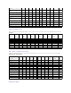
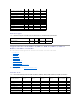
Back to Contents Page Supported Features Dell OpenManage Server Administrator Storage Management User's Guide Supported Features on the PERC 3/SC, 3/DC, 3/QC, 4/SC, 4/DC, 4/Di, 4e/Si, 4e/Di, 4e/DC, CERC ATA100/4ch, and 4/IM Controllers Supported Features on the PERC 3/Si, 3/Di, CERC SATA1.5/2s, and CERC SATA1.
(Manual mode is not available). Start Patrol Read No No No No No No No No No No No Stop Patrol Read No No No No No No No No No No No Battery Tasks Table A-2.
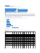
Virtual Disk Task Name PERC 3/SC PERC 3/DC PERC 3/QC PERC 4/SC PERC 4/DC PERC 4/DI PERC 4e/SI PERC 4e/DI PERC 4e/DC CERC ATA 100/4ch PERC 4/IM Assign and Unassign Dedicated Hot Spare Yes Yes Yes Yes Yes Yes Yes Yes Yes Yes No Create Virtual Disk Yes Yes Yes Yes Yes Yes Yes Yes Yes Yes No Create Virtual Disk Advanced Wizard Yes Yes Yes Yes Yes Yes Yes Yes Yes Yes No Create Virtual Disk Express Wizard Yes Yes Yes Yes Yes Yes Yes Yes Yes Yes No Rename
Minimum Number of Physical Disks in a RAID 0 1 1 1 1 1 1 1 1 1 1 NA Minimum Number of Physical Disks in a RAID 1 2 2 2 2 2 2 2 2 2 2 2 Minimum Number of Physical Disks in a RAID 5 3 3 3 3 3 3 3 3 3 3 NA Minimum Number of Physical Disks in a RAID 10 4 4 4 4 4 4 4 4 4 4 NA Minimum Number of Physical Disks in a RAID 50 6 6 6 6 6 6 6 6 6 NA NA Maximum number of physical disks in NA a RAID 6 NA NA NA NA NA NA NA NA NA NA Maximum number of phy
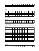
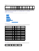
Table A-9. Enclosure Support on the PERC 3/SC, 3/DC, 3/QC, 4/SC, 4/DC, 4/Di, 4e/Si, 4e/Di, 4e/DC, CERC ATA100/4ch, and 4/IM Controllers Enclosure Support PERC 3/SC PERC 3/DC PERC 3/QC PERC 4/SC PERC 4/DC PERC 4/DI PERC 4e/SI PERC 4e/DI PERC 4e/DC CERC ATA 100/4ch PERC 4/IM Can an enclosure be attached to this controller? Yes Yes Yes Yes Yes Yes Yes Yes Yes No No Supported Features on the PERC 3/Si, 3/Di, CERC SATA1.5/2s, and CERC SATA1.
Recondition Battery Yes Yes No No Start Learn Cycle No No No No Delay Learn Cycle No No No No Connector Tasks Table A-12. Connector Tasks Supported by the PERC 3/Si, 3/Di, CERC SATA1.5/2s, and CERC SATA1.5/6ch Controllers Connector Task Name PERC 3/SI PERC 3/DI CERC SATA 2S CERC SATA 6ch Connector Rescan Yes Yes Yes Yes Physical Disk Tasks Table A-13. Physical Disk Tasks Supported by the PERC 3/Si, 3/Di, CERC SATA1.5/2s, and CERC SATA1.
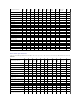
Restore Dead Disk Segments Yes Yes No Yes Initialize Virtual Disk No No No No Fast Initialize Virtual Disk No No No No Slow Initialize Virtual Disk No No No No Cancel Initialize Virtual Disk No No No No Virtual Disk Specifications Table A-15. Virtual Disk Specifications for the PERC 3/Si, 3/Di, CERC SATA1.5/2s, and CERC SATA1.
Read, Write, and Cache Policy PERC 3/SI PERC 3/DI CERC SATA 2S CERC SATA 6ch Cache settings Yes Yes No Yes Read Policy Yes Yes No Yes Read Ahead (Enabled) Yes Yes No Yes Adaptive Read Ahead No No No No No Read Ahead (Disabled) Yes Yes Yes Yes Write Policy Yes Yes No Yes Write Back (Enabled) No No No No Write Through (Disabled) Yes Yes Yes Yes Force Write Back (Enabled Always) No No No No Write Cache Enabled Protected Yes Yes No Yes Cache Policy No No No
Set Reconstruct Rate Yes Yes Yes Yes Yes Yes Rescan Controller No No No No No No Create Virtual Disk Yes Yes Yes Yes Yes Yes Export Log File Yes Yes Yes Yes Yes Yes Clear Foreign Configuration Yes Yes Yes Yes Yes Yes Import Foreign Configuration Yes Yes Yes Yes Yes Yes Import/Recover Foreign Configuration Yes with firmware 5.1.x or greater. Yes with firmware 5.1.x or greater.
Spare Prepare to Remove No No No No No No Offline Yes Yes Yes Yes Yes Yes Online Yes Yes Yes Yes Yes Yes Initialize No No No No No No Rebuild Yes Yes Yes Yes Yes Yes Cancel Rebuild Yes Yes Yes Yes Yes Yes Remove Dead Disk Segments No No No No No No Format Disk No No No No No No Clear Yes Yes Yes Yes Yes Yes Cancel Clear Yes Yes Yes Yes Yes Yes Cancel Replace Member No No Yes with firmware 6.1 and later Yes with firmware 6.
Maximum Number of Spans per Virtual Disk 8 8 8 8 8 8 Maximum Number of Physical Disks per Span 32 32 32 32 32 32 Minimum Stripe Size 8k 8k 8k 8k 8k 8k Maximum Stripe Size 128k 128k 1MB 1MB 1MB 1MB Maximum Number of Virtual Disks per Disk Group 16 16 16 16 16 16 Maximum Number of Physical Disks that Can Be Concatenated NA NA NA NA NA NA Maximum Number of Physical Disks in a RAID 0 32 32 32 32 32 32 Maximum Physical Disks in a RAID 1 2 2 2 2 2 2 Maximum N
Direct I/O No No No No No No Enclosure Support Table A-27.
Hot-plug of Enclosures Yes No No No Change Controller Properties Yes Yes Yes Yes Intelligent Mirroring Yes Yes Yes Yes Redundant Path Configuration Yes No No No Disk Cache Policy Yes Yes Yes Yes Managing Preserved Cache Yes Yes Yes Yes Manage Security Key Yes Yes Yes Yes Persistent Hot Spare Yes with firmware 7.1 and later Yes with firmware 7.1 and later Yes with firmware 7.1 and later Yes with firmware 7.1 and later Manage Physical Disk Power Yes with firmware 7.
Virtual Disk Tasks Table A-32.
Minimum Number of Physical Disks in a RAID 5 3 3 3 3 Minimum Number of Physical Disks in a RAID 10 4 4 4 4 Minimum Number of Physical Disks in a RAID 50 6 6 6 6 Maximum number of physical disks in a RAID 6 32 32 32 32 Maximum number of physical disks in a RAID 60 256 256 256 256 Minimum number of physical disks in a RAID 6 4 4 4 4 Minimum number of physical disks in a RAID 60 8 8 8 8 Supported RAID Levels Table A-34.
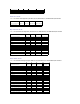
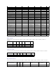
This section identifies the controller-supported features and whether or not an enclosure can be attached to the controller. l "Controller Tasks" l "Battery Tasks" l "Connector Tasks" l "Physical Disk Tasks" l "Virtual Disk Tasks" l "Virtual Disk Specifications" l "Supported RAID Levels" l "Read, Write, Cache and Disk Cache Policy" l "Enclosure Support" For enclosure-supported tasks, see "Enclosure and Backplane Features." Controller Tasks Table A-37.
Connector Task Name SAS 5/IR SAS 6/iR PERC H200 Connector Rescan No No No Physical Disk Tasks Table A-40. Physical Disk Tasks Supported on the SAS 5/iR, SAS 6/iR, and H200 Controllers Physical Disk Task Name SAS 5/IR SAS 6/iR PERC H200 Blink/Unblink Yes Yes Yes Task only available when an enclosure or backplane and LEDs on the physical disks are present.
Restore Dead Disk Segments No No No Initialize Virtual Disk No No No Fast Initialize Virtual Disk No No No Slow Initialize Virtual Disk No No No Cancel Initialize Virtual Disk No No No Supported RAID Levels Table A-42. RAID Levels Supported by the SAS 5/iR, SAS 6/iR, and H200 Controllers RAID Level SAS 5/IR SAS 6/iR PERC H200 RAID 0 Yes Yes Yes RAID 1 Yes Yes Yes RAID 10 No No Yes Virtual Disk Specifications Table A-43.
Read, Write, and Cache Policy SAS 5/IR SAS 6/iR PERC H200 Cache settings No No No Read Policy No No No Read Ahead (Enabled) No No No Adaptive Read Ahead No No No No Read Ahead (Disabled) No No No Write Policy No No No Write Back No No No Write Through No No No Force Write Back (Enabled Always) No No No Write Cache Enabled Protected No No No Cache Policy No No No Disk Cache Policy Yes Yes Yes Cache I/O No No No Direct I/O No No No Enclosure Support Tab
Virtual Disk Tasks Table A-48.
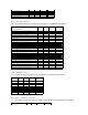
Read, Write, Cache and Disk Cache Policy Table A-51.
Set Check Consistency Rate No No Set Reconstruct Rate No No Rescan Controller No No Create Virtual Disk No No Export Log File No No Clear Foreign Configuration No No Import Foreign Configuration No No Import/Recover Foreign Configuration No No Set Patrol Read Mode No No Start Patrol Read No No Stop Patrol Read No No Battery Tasks Table A-54.
Assign and Unassign Dedicated Hot Spare No No Create Virtual Disk No No Create Virtual Disk Advanced Wizard No No Create Virtual Disk Express Wizard No No Rename No No Blink/Unblink No No Reconfigure No No Change Policy No No Split Mirror No No Unmirror No No Delete Last Virtual Disk No No Delete (any) Virtual Disk No No Check Consistency No No Cancel Check Consistency No No Pause Check Consistency No No Resume Check Consistency No No Cancel Background Initiali
Enable Alarm No Yes Yes Yes Yes Yes Disable Alarm No Yes Yes Yes Yes Yes Set Temperature Probe Values Yes Yes Yes Yes Yes Yes Set Asset Data (includes asset tag and asset name) Yes Yes Yes Yes Yes Yes Blink Enclosure No No Yes Yes Yes Yes No No Yes Yes Yes Yes Controller Reports Slot Occupancy Report Table A-60.
Back to Contents Page Determining the Health Status for Storage Components Dell OpenManage Server Administrator Storage Management User's Guide Health Status Rollup: Physical Disks in a Virtual Disk are Unsupported, Partially or Permanently Degraded Health Status Rollup: Physical Disks in a Virtual Disk are Failed or Removed Health Status Rollup: All Physical Disks in a Virtual Disk are in Foreign State Health Status Rollup: Some Physical Disks in a Virtual Disk are in Foreign State Health Status Rollu
Storage Subsystem Controller Battery Connector Physical Disk(s) Firmware/ Virtual Disk(s) Driver Component Status Health Rollup Health Status Rollup: All Physical Disks in a Virtual Disk are in Foreign State Table B-4.
Storage Subsystem Controller Battery Connector Physical Disk(s) Firmware/Driver Virtual Disk(s) Component Status Health Rollup Health Status Rollup: Unsupported Firmware Version Table B-8. Health Status Rollup: Unsupported Firmware Version (Enclosures Not Included) Storage Subsystem Controller Battery Connector Physical Disk(s) Firmware/Driver Virtual Disk(s) Component Status Health Rollup Health Status Rollup: Enclosure Power Supply Failed or Power Connection Removed Table B-9.
Health Rollup NA Health Status Rollup: One Enclosure Temperature Probe is Failed Table B-12. Health Status Rollup: One Enclosure Temperature Probe is Failed Storage Subsystem Controller Connector Enclosure Enclosure Temperature Probe Virtual Disks Physical Disks Component Status Health Rollup NA Health Status Rollup: Lost Both Power Connections to the Enclosure Table B-13.
Storage Subsystem Controller Connector Enclosure Enclosure Component Virtual Disks Physical Disks Component Status Health Rollup Back to Contents Page NA NA
Back to Contents Page Physical Disks Dell OpenManage Server Administrator Storage Management User's Guide Add a New Disk to Your System How to Avoid Removing the Wrong Disk Replacing a Physical Disk Receiving SMART Alerts Physical Disk Properties and Tasks Other Disk Procedures Blink and Unblink (Physical Disk) Remove Dead Segments Prepare to Remove Initialize Cancel Rebuild Rebuild Assign and Unassign Global Hot Spare Online and Offline Clear Physical Disk and Cancel Clear Revertible Hot Spare
If the disk is part of a redundant virtual disk: 1. Select the redundant virtual disk that includes the physical disk that is receiving SMART alerts and perform the Check Consistency task. See "Check Consistency" for more information. CAUTION: To avoid potential data loss, you should perform a check consistency before removing a physical disk that is receiving SMART alerts.
Normal/OK Warning/Non-critical Critical/Fatal See "Storage Component Severity" for more information. Power Status The following status of the physical drives. These statuses are present only for H700 and H800 controllers. These icons will not be present in the Physical Disk for Virtual Disk page. Spun Down The physical drive is in the spun down state. Only hot spare and unconfigured disk can be in spun down state if no activity happens on the drives for a specified interval of time.
You may also want to review the Alert Log to see whether the physical disk has generated alerts pertaining to a SMART predictive failure. These alerts can assist you in identifying the cause of the SMART alert. The following alerts may be generated in response to a SMART alert: 2094 2106 2107 2108 2109 2110 2111 For information on Alert Messages, see the Dell OpenManage Server Administrator Messages Reference Guide on the Dell Support website at support.dell.com/manuals.
2. Expand a controller object. 3. Expand a Connector object. 4. Expand the enclosure or Backplane object. 5. Select the Physical Disks object. 6. Select the Information/Configuration subtab. 7. Select a task from the Available Tasks drop-down menu. 8. Click Execute. NOTE: Different controllers support different features. For this reason, the tasks displayed on the Tasks drop-down menu can vary depending on which controller is selected in the tree view.
Prepare to Remove Does my controller support this feature? See "Supported Features." Use the Prepare to Remove task to spin down a physical disk so that it can safely be removed from an enclosure or backplane. It is recommended that you perform this task before removing a disk to prevent data loss. This task causes the lights on the disk to blink. You can safely remove the disk under the following conditions: l Wait for about 30 seconds to allow the disk to spin down.
disk fails, the assigned hot spare is activated to replace the failed physical disk without interrupting the system or requiring your intervention. When a hot spare is activated, it rebuilds the data for all redundant virtual disks that were using the failed physical disk. You can change the hot spare assignment by unassigning a disk and choosing another disk as needed. You can also assign more than one physical disk as a global hot spare.
Clear Physical Disk and Cancel Clear Does my controller support this feature? See "Supported Features." Use the clear physical disk task to erase data residing on a physical disk. The Clear task applies to physical disks that are in Ready state and that contain data or that are in Clear state. NOTE: A physical disk may display the Clear state if it is a member of a virtual disk that is being slow initialized.
1. Expand the Storage tree object to display the controller objects. 2. Select a controller object on which you want to enable the revertible hot spare task and select the Information/Configuration tab. 3. From the Controller Task drop down menu, select Change Controller Properties and click Execute. NOTE: The Rebuild rate for Revertible Hot Spare will be the same as defined for the controller. Instant Secure Erase Does my controller support this feature? See "Supported Features.
Back to Contents Page RAID Controller Batteries Dell OpenManage Server Administrator Storage Management User's Guide Battery Properties and Tasks Some RAID controllers have batteries. If the controller has a battery, Storage Management displays the battery under the controller object in the tree view. In the event of a power outage, the controller battery preserves data that is in the nonvolatile cache memory (NVRAM) but not yet written to disk.
State This property displays the current status of the battery. Possible values are: Ready — The battery is functioning normally. Degraded — The battery needs to be reconditioned. Reconditioning — The battery is being reconditioned. See "Recondition Battery" for more information. Charging — The battery is undergoing the recharge phase of the battery Learn cycle. See "Start Learn Cycle" for more information. Learning — The battery is undergoing the discharge phase of the battery Learn cycle.
Drop-down Menu Battery Tasks: l "Recondition Battery" l "Start Learn Cycle" l "Battery Delay Learn Cycle" Recondition Battery Does my controller support this feature? See "Supported Features." Some controllers have NiMHi batteries which need to be reconditioned approximately every six months to maintain reliability. This reconditioning cycle requires a full discharge and recharge of the battery.
Battery Delay Learn Cycle Does my controller support this feature? See "Supported Features." The controller firmware automatically initiates the battery Learn cycle every 90 days. Although you cannot stop the firmware from running the Learn cycle, you can delay the start time of the Learn cycle for up to seven days. See "Start Learn Cycle" for more information on the battery Learn cycle. To delay the battery Learn cycle: 1. Type a numerical value in the Days text box.
Back to Contents Page BIOS Terminology Dell OpenManage Server Administrator Storage Management User's Guide BIOS Terms and the PERC 3/SC, 3/DC, 3/QC, 4/SC, 4/DC, 4e/DC, 4/Di, and CERC ATA100/4ch Controllers BIOS Terms and the PERC 3/Si, 3/Di, CERC SATA1.5/6ch, and CERC SATA1.5/2s Controllers The terminology used by Storage Management can be different from the terminology used in the controller BIOS. The following sections show some of these differences.
Back to Contents Page Connectors Dell OpenManage Server Administrator Storage Management User's Guide Channel Redundancy and Thermal Shutdown Channel Redundancy on PERC 3/DC, 3/QC, 4/DC, 4e/DC, 4/Di, and 4e/Di Controllers Creating a Channel-redundant Virtual Disk Connector Health Connector Properties and Tasks Logical Connector Properties and Tasks A controller contains one or more connectors (channels or ports) to which you can attach disks.
l ¡ PERC 3/DC, 3/QC, 4/DC, 4e/DC, 4/Di, and 4e/Di Controllers: It is recommended that you only use RAID 10 or RAID 50. ¡ PERC 3/Di Controller: It is recommended that you only use RAID 10. Complete "Create Virtual Disk Advanced Wizard (Step 2 of 4)." In this step, you select the channels and the disks to be used by the virtual disk. The selections you make determine whether or not the virtual disk is channel-redundant.
The component may still be functioning, but it could fail. The component may also be functioning in an impaired state. Data loss is possible. Critical/Failure/Error. The component has either failed or failure is imminent. The component requires immediate attention and may need to be replaced. Data loss may have occurred.
Does my controller support this feature? See "Supported Features." On a SCSI controller, this task rescans the controller connectors to verify the currently connected devices or to recognize new devices that have been added to the connectors. Performing a rescan on a connector is similar to performing a rescan on the controller. For information on when you may want to do a rescan, see "Rescan to Update Storage Configuration Changes." NOTE: Rescan is not supported on non-RAID SCSI controllers.
Clearing the Redundant Path View If you do not want the redundant path view, physically disconnect the connector port from the enclosure and reboot the system. After the system reboots, the user interface will still display the Logical Connector, but in a critical state. If you are certain you do not want the redundant path mode, select Clear Redundant Path view from the Connector Tasks.
Back to Contents Page Controllers Dell OpenManage Server Administrator Storage Management User's Guide What is a Controller? RAID Controller Features Controller-supported RAID Levels Controller-supported Stripe Sizes RAID Controller Read, Write, Cache, and Disk Cache Policy Creating and Deleting Virtual Disks on Cluster-enabled Controllers Background Initialization on PERC 3/SC, 3/DC, 3/QC, 4/SC, 4/DC, 4e/DC, 4/Di, 4e/Si, and 4e/Di Controllers Firmware/Driver Versions Cluster-enabled RAID Controllers
SAS RAID Controllers The following RAID controllers use Serial Attached SCSI (SAS) technology. l PERC 5/E l PERC 5/i Integrated l PERC 5/i Adapter l SAS 5/iR Integrated l SAS 5/iR Adapter l PERC 6/E l PERC 6/I controller family l SAS 6/iR controller family l PERC S100 and S300 controllers l PERC H200, H700, and H800 controllers RAID Controller Features Different controllers have different features.
When creating a virtual disk, you specify the read, write, and cache policies for the virtual disk. The following sub-section describes these policies. NOTE: Read, write, and cache policies are not supported on the CERC SATA1.5/2s controller. Read Policy Does my controller support this feature? See "Supported Features" The read policies indicate whether or not the controller should read sequential sectors of the virtual disk when seeking data. l l Read-Ahead.
The Direct I/O and Cache I/O cache policies apply to reads on a specific virtual disk. These settings do not affect the read-ahead policy. The cache policies are as follows: l l Cache I/O. Specifies that all reads are buffered in cache memory. Direct I/O. Specifies that reads are not buffered in cache memory. When using direct I/O, data is transferred to the controller cache and the host system simultaneously during a read request.
If you are using a PERC 3/DC, 4/DC, or 4e/DC controller in a cluster configuration, you must shut down and power off the other systems in the cluster before creating or deleting the virtual disk. The following procedure describes the sequence of actions required to create or delete a virtual disk from a clusterenabled controller.
The following non-RAID controllers use Serial Attached SCSI (SAS) technology. l SAS 5/i Integrated l SAS 5/E l SAS 6Gbps Adapter Firmware/Driver Versions Use this window to view information about the controller firmware and drivers. For more information on firmware and drivers, see "Installation Considerations for Storage Management." Firmware/Driver Properties The firmware and driver properties can vary depending on the model of the controller.
Normal/OK. The component is working as expected. Warning/Non-critical. A probe or other monitoring device has detected a reading for the component that is above or below the acceptable level. The component may still be functioning, but it could fail. The component may also be functioning in an impaired state. Data loss is possible. Critical/Failure/Error. The component has either failed or failure is imminent. The component requires immediate attention and may need to be replaced.
NOTE: On some controllers, Storage Management may not be able to obtain the firmware version. In this case, Storage Management displays Not Applicable. Minimum Required Firmware Version This property displays the minimum firmware version that is required by Storage Management. This property is only displayed if the controller firmware does not meet the minimum requirement. The firmware and drivers listed in the Readme file refer to the minimum supported version for these controllers.
Active — The Patrol Read process is currently running. Stopped — The Patrol Read has been stopped. For more information about Patrol Read, see "Set Patrol Read Mode." Patrol Read Iterations This property displays the number of Patrol Read iterations. For more information about Patrol Read, see "Set Patrol Read Mode." Cluster Mode This property indicates whether the controller is part of a cluster configuration. SCSI Initiator ID This property displays the SCSI ID of a SCSI controller.
l "Set Patrol Read Mode" l "Start and Stop Patrol Read" l "Manage Preserved Cache" l "Change Controller Properties" l "Manage Physical Disk Power" Available Reports Do the following to view a report: 1. Expand the Storage tree object to display the controller objects. 2. Select a controller object. 3. Select the Information/Configuration subtab. 4. Select a report from the Select Report drop-down menu. 5. Click Execute.
Does my controller support this feature? See "Supported Features." Use the Enable Alarm task to enable the controller's alarm. When enabled, the alarm sounds in the event of a device failure. Disable Alarm (Controller) Does my controller support this feature? See "Supported Features." Use the Disable Alarm task to disable the controller's alarm. When disabled, the alarm does not sound in the event of a device failure.
The Foreign Configuration Operations task provides a preview of the foreign configurations that you can import. This task is available on PERC 6 controllers with firmware version 6.1 and later. See "Foreign Configuration Operations" for more information. Manage Physical Disk Power Does my controller support this feature? See "Supported Features.
You will need to completely reconfigure your storage after performing this operation. CAUTION: Resetting a configuration permanently destroys all data on all virtual disks attached to the controller. If the system or boot partition resides on these virtual disks, it will be destroyed. NOTE: Resetting the controller configuration does not remove a foreign configuration. To remove a foreign configuration, use the "Clear Foreign Configuration" task. To reset the controller configuration: 1.
Foreign Configuration Operations NOTE: Foreign Configuration Operations is available only on SAS controllers with firmware versions 6.1 and later. A foreign configuration is data residing on physical disks that have been moved from one controller to another. Virtual disks residing on physical disks that have been moved are considered to be a foreign configuration. The Foreign Configuration Operations option is displayed only when a controller detects a foreign configuration.
l Dedicated Hot Spare Partially Foreign — The virtual disk is part of an already existing configuration. Some physical disks in this virtual disk are foreign. This property displays whether the foreign disk is a dedicated hot spare. Based on this information, you can decide whether you want to import, recover, or clear the foreign configuration. To preview the import of foreign configuration Click Foreign Configuration Operations from the Controller Tasks drop down menu.
For SAS controllers with firmware versions 6.1 and later: 1. Expand the Storage tree object to display the controller objects. 2. Select a controller object. 3. Select the Information/Configuration subtab. 4. Select Foreign Configuration Operations from the Controller Available Tasks drop-down menu. 5. Click Execute. 6. On the Foreign Configuration Preview page, click Import/Recover. For controllers with firmware version 6.0 and earlier: 1.
For controllers with firmware version 6.0 and earlier: 1. Expand the Storage tree object to display the controller objects. 2. Select a controller object. 3. Select the Information/Configuration subtab. 4. Select Clear Foreign Configuration from the Controller tasks.
support.dell.com/manuals. NOTE: On replacing a SMART error drive with a good drive on PERC4/IM controllers, it is necessary to perform a rescan operation on the controller, for Storage Management to display the correct status of the newly inserted drive. Progress This property displays the progress of an operation being performed on the physical disk. For example, if the physical disk is being rebuilt, then a value of 52% indicates that the rebuild is 52% complete.
background initialization task. At 0%, the background initialization will have the lowest priority for the controller, will take the most time to complete, and will be the setting with the least impact to system performance. A background initialization rate of 0% does not mean that the background initialization is stopped or paused.
Related Information: l "Check Consistency" l "Cancel Check Consistency" Set Reconstruct Rate Does my controller support this feature? See "Supported Features." The Set Reconstruct Rate task changes the amount of system resources dedicated to the reconstruct task. The reconstruct task remakes the virtual disk after you have changed the RAID level or otherwise reconfigured the virtual disk.
If the communication channel between the connector and the first enclosure is lost, the redundant path configuration itself is lost. In this case, the health of the logical connector is displayed as critical. Navigate to the Information/Configuration subtab of the logical connector to view details of the "Path Health." See the table below for a brief outline of this scenario.
l "Logical Connector Properties and Tasks" l "Enclosure and Backplane Properties and Tasks" Set Patrol Read Mode Does my controller support this feature? See "Supported Features." Patrol Read is a feature for identifying disk errors in order to avoid disk failures and data loss or corruption. The Patrol Read only runs on disks that are being used in a virtual disk or that are hot spares. When possible, the Patrol Read corrects disk errors and restores the integrity of the data.
Start and Stop Patrol Read Does my controller support this feature? See "Supported Features." When the Patrol Read mode is set to manual, you can start the Patrol Read task or stop the task when it is running. There are certain conditions under which the Patrol Read task cannot be run. See "Set Patrol Read Mode" for more information. To start or stop the Patrol Read task: Click Start Patrol Read or Stop Patrol Read when ready.
2. On the Storage Dashboard page, select Change Controller Properties... from the Available Tasks drop down menu. 3. Click Execute. Or: 1. Expand the Storage tree object to display the controller objects. 2. Select a controller object. 3. Select the Information/Configuration subtab. 4. Select Change Controller Properties... from the Controller Tasks drop down menu. 5. Click Execute.
Manage Preserved Cache The Managed Preserved Cache feature provides you the option to ignore or restore the controller cache data. In the write-back policy, data is written to the cache before being written to the physical disk. If the virtual disk goes offline or is deleted for any reason, the data in the cache is lost. Data in the cache may also be lost in case of unintended cable or power failure.
A Security Key Identifier can contain numerals, lowercase alphabets, uppercase alphabets, non-alphanumeric characters, or a combination of any of these. 2. Enter a Passphrase. A Passphrase must contain at least one numeral, one lowercase alphabet, one uppercase alphabet, and one non-alphanumeric character (except space.) NOTE: Server Administrator Storage Management provides a suggested Passphrase below the Passphrase text box. 3.
This report provides information on all the Consistency Checks done on the controller in a chronological order. It provides information such as last run time and result. If the Consistency Check fails, it provides the reason for the failure. To locate this task in Storage Management: 1. Click Storage to view the dash board. 2. Select View Check Consistency Report from the Select Report drop- down menu. 3. Click Execute.
Back to Contents Page Enclosures and Backplanes Dell OpenManage Server Administrator Storage Management User's Guide Backplanes SMART Thermal Shutdown Enclosure Management Enclosure and Backplane Properties and Tasks Enclosures Changing the Mode on PowerVault 220S and PowerVault 221S Enclosures Enclosure and Backplane Health Set Asset Data Set Temperature Probe Values EMM Properties View Slot Occupancy Report Fan Properties Power Supply Properties Temperature Probe Properties and Tasks Physical disks
Enclosure Power Supplies The enclosure's power supplies are displayed under the Power Supplies object in the tree view. You can select the Power Supplies object to display their status information. Enclosure Temperature Probes The enclosure's temperature probes are displayed under the Temperatures object. You can select the Temperatures object to display their status information.
Changing the Mode on PowerVault 220S and PowerVault 221S Enclosures When toggling the bus configuration switch on a PowerVault 220S or PowerVault 221S enclosure, the enclosure should be powered off. The bus configuration switch is used to change the enclosure to split bus, joined bus, or clustered mode. If you change the PowerVault 220S or PowerVault 221S enclosure mode with the enclosure powered on, the enclosure may no longer be displayed by Storage Management and you may notice other erratic behaviors.
l "Physical Disks" Enclosure and Backplane Properties and Tasks Use this window to view information about the enclosure or backplane and execute enclosure tasks. Enclosure and Backplane Properties The enclosure or backplane properties can vary depending on the model of the controller. Enclosure or backplane properties may include: Property Definition These icons represent the severity or health of the storage component. See "Storage Component Severity" for more information.
Enclosure Part Number This property displays the part number of the enclosure. Enclosure Alarm This property displays whether the enclosure's alarm is enabled or disabled. Enclosure Tasks Do the following to execute a drop-down menu enclosure task: 1. Expand the Storage tree object to display the controller objects. 2. Expand a controller object. 3. Expand a Connector object. 4. Select the enclosure object. 5. Select the Information/Configuration subtab. 6.
l The enclosure temperature has exceeded the warning threshold. l A power supply, fan, or enclosure management module (EMM) has failed. l The split bus is not installed. (A split bus is indicated by a single triangle symbol on the back of the enclosure.) Disable Alarm (Enclosure) Does my enclosure support this feature? See "Supported Features." Use the Disable Alarm task to disable the enclosure alarm.
Checking the Enclosure's Temperature Does my controller support this feature? See "Supported Features." To check the enclosure's temperature: 1. Expand the tree view until the Temperatures object is displayed. 2. Select the Temperatures object. The temperature reported by the temperature probe is displayed in Celsius in the Reading column in the right pane.
3. Click Apply Changes. If you want to exit and cancel your changes, click Go Back To Enclosure Information Page. To locate this task in Storage Management: 1. Expand the Storage tree object to display the controller objects. 2. Expand a controller object. 3. Expand a Connector object. 4. Select the enclosure object. 5. Select the Information/Configuration subtab. 6. Select Set Asset Data from the Available Tasks drop-down menu. 7. Click Execute.
View Slot Occupancy Report Does my controller support this feature? See "Supported Features." The View Occupancy Slot Report task allows you to view empty and occupied slot details of the selected enclosure. It provides a diagram that represents the occupancy of physical drive slots. Move the mouse over each slot to view details, such as physical disk ID, state, and size. To locate this task in Storage Management: 1. Expand the Storage tree object to display the controller objects. 2.
Firmware Version This property indicates the version of the firmware loaded on the EMM. All EMM modules in the enclosure should have the same level of firmware. SCSI Rate This property displays the maximum SCSI speed that the EMM in a SCSI enclosure supports. Fan Properties Use this window to view information about the enclosure's fans. The fans are a component of the enclosure's cooling module. The following table describes the fan properties.
Ready — The power supply is functioning normally. Degraded — The power supply has encountered a failure and is operating in a degraded state. Failed — The power supply has encountered a failure and is no longer functioning. Storage Management may also be unable to communicate with the enclosure using SES commands. The Failed state is displayed when the enclosure does not respond to a status query from Storage Management for any reason.
1. Expand the Storage tree object to display the controller objects. 2. Expand a controller object. 3. Expand a Connector object. 4. Expand the enclosure object. 5. Select the Temperatures object. 6. Click Set Temperature Probe.
Back to Contents Page Frequently Asked Questions Dell OpenManage Server Administrator Storage Management User's Guide Why is a rebuild not working? How can I safely remove or replace a physical disk? How do I recover from removing the wrong physical disk? How do I know what firmware is installed? What controllers do I have? How do I turn off an alarm? What RAID level is best for me? This section provides frequently asked questions that address situations commonly experienced in a storage environment.
What controllers do I have? Each controller attached to the system is displayed under the Storage object in the tree view. In addition, the Storage object's Health and Information/Configuration subtabs display information for each controller. To identify which controllers are attached to the system: 1. Select the Storage tree view object. The Health subtab displays the name and status for each controller attached to the system. 2.
Back to Contents Page Getting Started Dell OpenManage Server Administrator Storage Management User's Guide Launching Storage Management User Privileges Using the Graphical User Interface Using the Storage Management Command Line Interface Displaying the Online Help Common Storage Tasks Dell OpenManage Server Administrator Storage Management is designed for system administrators who implement hardware RAID solutions and understand corporate and small business storage environments.
User and Power User privileges allow you to view storage status, but not manage or configure storage. With User and Power User privileges, you can use the omreport storage command but not the omconfig storage command. For more information on user groups and other Server Administrator security features, see the Dell OpenManage Server Administrator User's Guide.
l Assign a hot spare to the virtual disk. When a virtual disk uses a redundant RAID level, then you can assign a hot spare (backup physical disk) to rebuild data if a physical disk in the virtual disk fails. For more information, see: ¡ l l "Protecting Your Virtual Disk with a Hot Spare." This section describes hot spares and includes controller-specific information. Perform a Check Consistency.
Back to Contents Page Protecting Your Virtual Disk with a Hot Spare Dell OpenManage Server Administrator Storage Management User's Guide Understanding Hot Spares Considerations for Hot Spares on PERC 3/SC, 3/DC, 3/QC, 4/SC, 4/DC, 4e/DC, 4/Di, 4e/Si, 4e/Di, CERC ATA100/4ch, PERC 5/E, PERC 5/i, PERC 6/E, PERC 6/I, and CERC 6/I Controllers Considerations for Hot Spares on PERC 3/Si, 3/Di, CERC SATA1.
Dedicated Hot Spare Considerations The following considerations apply to dedicated hot spares: l Considerations for RAID 10, RAID 50, and RAID 60. If you have created a RAID 10 or RAID 50 virtual disk that does not fully consume its member physical disks, then you will not be able to assign a dedicated hot spare to the RAID 10 or RAID 50 virtual disk. Storage Management does not allow you to create RAID 10 and RAID 50 virtual disks from partial physical disks.
The SAS 6/iR controller enables you to assign two global hot spares. The controller firmware remembers the hot spare assignment even after the physical disks that you assigned as hot spares have been removed. In other words, in the case of a disk removal, the firmware may assume that a hot spare is present when it is not. In this case, the firmware may prevent you from assigning a new global hot spare as the firmware assumes that a global hot spare is already assigned.
Back to Contents Page Setting Hot Spare Protection Policy Dell OpenManage Server Administrator Storage Management User's Guide Dedicated Hot Spare Protection Policy Global Hot Spare Protection Policy Considerations for Hot Spare Protection Policy Considerations for Enclosure Affinity The Hot Spare Protection Policy is supported only on Serial Attached SCSI (SAS) controllers.
l Enclosure affinity settings for a global/dedicated hot spare are not automatically set when you upgrade to Dell OpenManage version 6.1. l Enclosure affinity settings for a global/dedicated hot spare are not automatically set when you import a foreign virtual disk.
Back to Contents Page Moving Physical and Virtual Disks from One System to Another Dell OpenManage Server Administrator Storage Management User's Guide Required Conditions Migrating SCSI Virtual Disks to Another System Migrating SAS Virtual Disks to Another System This section describes how to move physical and virtual disks from one system to another.
Moving the Disks 1. Shut down the system that the physical disks are being moved from. 2. If the receiving controller has a preexisting virtual disk configuration on attached physical disks, use the following procedure for clearing the configuration: ¡ Shut down the receiving server. ¡ Remove all the physical disks from the controller. ¡ Start up the receiving server and clear the configuration from the controller BIOS.
Back to Contents Page Dell™ OpenManage™ Server Administrator Storage Management User's Guide NOTE: A NOTE indicates important information that helps you make better use of your computer. CAUTION: A CAUTION indicates potential damage to hardware or loss of data if instructions are not followed. Information in this document is subject to change without notice. © 2010 Dell Inc. All rights reserved. Reproduction in any manner whatsoever without the written permission of Dell Inc. is strictly forbidden.
Back to Contents Page Overview Dell OpenManage Server Administrator Storage Management User's Guide What's New in this Release? Installation Considerations for Storage Management Supported Controllers Supported Enclosures Support for Disk and Volume Management Support for Security Key Management Dell OpenManage Server Administrator Storage Management provides enhanced features for configuring a system's locally-attached RAID and non-RAID disk storage.
NOTE: It is highly recommended that you uninstall FAST before installing Storage Management. Uninstalling FAST on a system that has both FAST and Storage Management installed will also uninstall the Adaptec filter driver. In this situation, you will need to reinstall Storage Management to restore the Adaptec filter driver. To prevent this, verify that FAST is uninstalled before installing Storage Management.
l PERC H200 Adapter, PERC H200 Integrated, and PERC H200 Modular l PERC H800 Adapter, PERC H700 Adapter, PERC H700 Integrated, and PERC H700 Modular NOTE: Integrated mirroring on the PERC 4/IM controller enables you to mirror a physical disk that resides internally in the server. You can implement the integrated mirror using the PERC 4/IM BIOS. When implemented, Storage Management recognizes the integrated mirror as a virtual disk.
Back to Contents Page Quick Access to Storage Status and Tasks Dell OpenManage Server Administrator Storage Management User's Guide Storage Dashboard and Storage Health Storage Health Hot Spare Protection Policy Select Report Storage Component Severity Alerts or Events Storage Properties and Current Activity Monitoring Disk Reliability on RAID Controllers Using Alarms to Detect Failures Using Enclosure Temperature Probes Rescan to Update Storage Configuration Changes Time Delay in Displaying Confi
Warning/Non-critical. A probe or other monitoring device has detected a reading for the component that is above or below the acceptable level. The component may still be functioning, but it could fail. The component may also be functioning in an impaired state. Data loss is possible. Critical/Failure/Error. The component has either failed or failure is imminent. The component requires immediate attention and may need to be replaced. Data loss may have occurred.
Using Enclosure Temperature Probes Physical disk enclosures have temperature probes that warn you when the enclosure has exceeded an acceptable temperature range.
Back to Contents Page
Back to Contents Page Storage Information and Global Tasks Dell OpenManage Server Administrator Storage Management User's Guide Storage Properties Global Tasks Storage Controllers Use this window to view high-level information about your system's storage. This window also enables you to launch global tasks that affect all controllers attached to the system. Storage Properties The Storage tree-view object has the following properties.
Enable/Disable Smart Thermal Shutdown By default, the operating system and server shut down when the PowerVault 220S and PowerVault 221S enclosures reach a critical temperature of 0 or 50 degrees Celsius. Using the Enable Smart Thermal Shutdown task, however, you can specify that only the enclosure, and not the operating system and server be shut down when the enclosure reaches a critical temperature.
SCSI Initiator ID This property displays the SCSI ID of a SCSI controller. The default value is usually 7. You can change the default value in the BIOS. Controllers in a cluster configuration should not have duplicate SCSI Initiator IDs. Refer to SCSI documentation for a list of acceptable SCSI Initiator ID values. On some controllers, this property is not available. In this case, this property displays as Not Applicable.
Back to Contents Page Understanding RAID Concepts Dell OpenManage Server Administrator Storage Management User's Guide What Is RAID? Organizing Data Storage for Availability and Performance Choosing RAID Levels and Concatenation Comparing RAID Level and Concatenation Performance No-RAID Storage Management uses Redundant Array of Independent Disks (RAID) technology to provide storage management capability.
RAID provides different methods or RAID levels for organizing the disk storage. Some RAID levels maintain redundant data so that you can restore data after a disk failure. Different RAID levels may also entail an increase or decrease in the system's I/O (read and write) performance. Maintaining redundant data requires the use of additional physical disks. As more disks become involved, the likelihood of a disk failure increases.
l Concatenates n disks as one large virtual disk with a capacity of n disks. l Data fills up the first disk before it is written to the second disk. l No redundancy data is kept. When a disk fails, the large virtual disk fails. l No performance gain. l No redundancy.
l "Organizing Data Storage for Availability and Performance" l "Comparing RAID Level and Concatenation Performance" l "Controller-supported RAID Levels" l "Number of Physical Disks per Virtual Disk" l "Maximum Number of Virtual Disks per Controller" RAID Level 1 (Mirroring) RAID 1 is the simplest form of maintaining redundant data. In RAID 1, data is mirrored or duplicated on one or more physical disks.
RAID 5 Characteristics: l Groups n disks as one large virtual disk with a capacity of (n-1) disks. l Redundant information (parity) is alternately stored on all disks. l When a disk fails, the virtual disk still works, but it is operating in a degraded state. The data is reconstructed from the surviving disks. l Better read performance, but slower write performance. l Redundancy for protection of data.
l Groups n disks as one large virtual disk with a capacity of (n-2) disks. l Redundant information (parity) is alternately stored on all disks. l The virtual disk remains functional with up to two disk failures. The data is reconstructed from the surviving disks. l Better read performance, but slower write performance. l Increased redundancy for protection of data. l Two disks per span are required for parity. RAID 6 is more expensive in terms of disk space.
See the following: l "Organizing Data Storage for Availability and Performance" l "Comparing RAID Level and Concatenation Performance" l "Controller-supported RAID Levels" l "Number of Physical Disks per Virtual Disk" l "Maximum Number of Virtual Disks per Controller" RAID Level 60 (Striping over RAID 6 sets) RAID 60 is striping over more than one span of physical disks that are configured as a RAID 6.
RAID 10, data is striped across multiple physical disks. The striped disk group is then mirrored onto another set of physical disks. RAID 10 can be considered a mirror of stripes. Figure 3-8. Striping Over Mirrored Disk Groups RAID 10 Characteristics: l Groups n disks as one large virtual disk with a capacity of (n/2) disks, where n is an even integer. l Mirror images of the data are striped across sets of physical disks. This level provides redundancy through mirroring.
Related Information: See the following: l "Organizing Data Storage for Availability and Performance" l "Comparing RAID Level and Concatenation Performance" l "Controller-supported RAID Levels" l "Number of Physical Disks per Virtual Disk" l "Maximum Number of Virtual Disks per Controller" Considerations for RAID 10 and 50 on PERC 3/SC, 3/DC, 3/QC, 4/SC, 4/DC, 4e/DC, 4/Di, 4e/Si, 4e/Di, and CERC ATA100/4ch Controllers On the PERC 3/SC, 3/DC, 3/QC, 4/SC, 4/DC, 4e/DC, 4/Di, 4e/Si, 4e/Di, and CERC ATA
records) RAID 50 Good Very Good Fair Fair N+2 (N = at least 4) Medium-sized transactional or data-intensive uses RAID 6 Excellent Sequential reads: good. Transactional reads: Very good Fair, unless using write-back cache Poor N+2 (N = at least two disks) Critical information. Databases and other read-intensive transactional uses. RAID 60 Excellent Very Good Fair Poor X x (N + 2) (N = at least 2) Critical information. Medium-sized transactional or data-intensive uses.
Back to Contents Page Troubleshooting Dell™ OpenManage™ Server Administrator Storage Management User's Guide Common Troubleshooting Procedures Virtual Disk Troubleshooting Specific Problem Situations and Solutions This section contains troubleshooting procedures for common situations as well as for specific problems. Common Troubleshooting Procedures This section describes commands and procedures that can be used in troubleshooting.
On SCSI controllers, use the Rescan controller task to update information for the controller and attached devices. This operation may take a few minutes if there are a number of devices attached to the controller. If the Rescan does not properly update the disk information, you may need to reboot your system.
Does my controller support this feature? See "Supported Features" If you do not have a suitable backup available, and if the failed disk is part of a virtual disk on a controller that supports the Online physical disk task, then you can attempt to retrieve data by selecting Online from the failed disk's drop-down task menu. The Online command attempts to force the failed disk back into a Online state. If you are able to force the disk into a Online state, you may be able to recover individual files.
l "Cannot Create a Virtual Disk" l "Virtual Disk Errors on Linux" l "Problems Associated With Using the Same Physical Disks for Both Redundant and Nonredundant Virtual Disks" A Rebuild Does Not Work A rebuild will not work in the following situations: l The virtual disk is nonredundant. For example, a RAID 0 virtual disk cannot be rebuilt because RAID 0 does not provide data redundancy. l There is no hot spare assigned to the virtual disk.
l Is there adequate available space on the disk? The physical disks that you have selected for creating the virtual disk must have an adequate amount of free space available. l The controller may be performing other tasks, such rebuilding a physical disk, that must run to completion before the controller can create the new virtual disk.
l "Physical Disk is Offline or Displays an Error Status" l "A Disk is Marked as Failed When Rebuilding in a Cluster Configuration" l "A Disk on a PERC 4/Di Controller Does not Return Online after a Prepare to Remove" l "Receive a "Bad Block" Alert with "Replacement," "Sense," or "Medium" Error" l "Read and Write Operations Experience Problems" l "I/O Stops When a Redundant Channel Fails" l "A Task Menu Option is Not Displayed" l "A Corrupt Disk or Drive Message Suggests Running autocheck Duri
l Rebuild l Virtual disk format l I/O If you receive an alerts 2146 through 2150 as the result of doing a rebuild or while the virtual disk is in a degraded state, then data cannot be recovered from the damaged disk without restoring from backup. If you receive alerts 2146 through 2150 under circumstances other than a rebuild, then data recovery may be possible. The following describes each of these situations.
Storage Management May Delay Before Updating Temperature Probe Status In order to display the enclosure temperature and temperature probe status, Storage Management polls the enclosure firmware at regular intervals to obtain temperature and status information. On some enclosures, there is a short delay before the enclosure firmware reports the current temperature and temperature probe status.
Back to Contents Page Virtual Disks Dell OpenManage Server Administrator Storage Management User's Guide Considerations Before Creating Virtual Disks Reconfiguring/Migrating Virtual Disks Creating Virtual Disks Starting and Target RAID Levels for Virtual Disk Reconfiguration and Capacity Expansion Maintain Integrity of Redundant Virtual Disks Rebuilding Redundant Information Virtual Disk Bad Block Management Virtual Disk Properties and Tasks Create Virtual Disk Express Wizard (Step 1 of 2) Create V
in the original virtual disk. l Space allocation when deleting and creating virtual disks on PERC 3/SC, 3/DC, 3/QC, 4/SC, 4/DC, 4e/DC, 4/Di, 4e/Si, 4e/Di, and CERC ATA100/4ch controllers. When you delete a virtual disk, you free up or make available space on the physical disks that were being used by the deleted virtual disk. If you have created several virtual disks on a disk group, then deleting virtual disks can result in pockets of free space residing in various locations on the physical disks.
There are limitations on the number of physical disks that can be included in the virtual disk. These limitations depend on the controller. When creating a virtual disk, controllers support a certain number of stripes and spans (methods for combining the storage on physical disks). Because the number of total stripes and spans is limited, the number of physical disks that can be used is also limited.
You may also want to refer to the following related sections: l "What Is RAID?" l "Channel Redundancy and Thermal Shutdown" for information on creating a channel-redundant virtual disk l "Virtual Disk Task: Delete" l "Reconfiguring/Migrating Virtual Disks" l "Physical Disk Properties and Tasks" Reconfiguring/Migrating Virtual Disks Does my controller support this feature? See "Supported Features.
RAID 10 RAID 0, RAID 5, RAID 10 CERC SATA1.5/2s N/A N/A N/A PERC 6/E, PERC 6/I, CERC 6/I, PERC H800 Adapter, PERC H700 Adapter, PERC H700 Integrated, and PERC H700 Modular RAID 0 RAID 1 Add a single disk RAID 0 RAID 0, RAID 5 Add at least one additional disk. RAID 0 RAID 6 RAID 6 requires a minimum of 4 disks. Reconfiguration from RAID 0 to RAID 6 requires at least 2 additional disks even when this exceeds the 4-disk minimum required by RAID 6.
What is a Virtual Disk Bad Block? Virtual disk bad blocks are due to bad blocks on one or more member physical disks. Read operation on the virtual disks having bad blocks may fail. Storage Management generates a critical alert (2387) to notify you of the bad blocks on the virtual disk. Virtual disk bad blocks are discovered when the controller performs any operation that requires scanning the disk.
Virtual Disk Properties The virtual disk properties can vary depending on the model of the controller. Virtual disk properties may include: Property Definition Status These icons represent the severity or health of the storage component. Normal/OK Warning/Non-critical Critical/Fatal See "Storage Component Severity" for more information. Name This property displays the virtual disk name. State This property displays the current status of the virtual disk.
SAS — Serial Attached SCSI SATA — Serial Advanced Technology Attachment (SATA) Media This property displays the media type of the physical disks present in the virtual disk. The possible values are: HDD—Hard Disk Drive. A HDD is a non-volatile storage device which stores digitally-encoded data on rapidly rotating platters with magnetic surfaces. SSD—Solid State Drive. An SSD is a data storage device that uses solid-state memory to store persistent data.
l "Clear Virtual Disk Bad Blocks" l "Secure Virtual Disk" Reconfigure Does my controller support this feature? See "Supported Features." Use the Reconfigure task to change the virtual disks properties. For example, you can use this task to add physical disks or change the RAID level. See "Virtual Disk Task: Reconfigure (Step 1 of 3)" for more information. Format, Initialize, Slow and Fast Initialize Does my controller support this feature? See "Supported Features.
Assign and Unassign Dedicated Hot Spare Does my controller support this feature? See "Supported Features." Use the Assign Dedicated Hot Spare task to assign a disk as a backup for a single virtual disk. See "Assign and Unassign Dedicated Hot Spare" for more information. Check Consistency Does my controller support this feature? See "Supported Features." Use the Check Consistency task to verify the accuracy of the redundant (parity) information. This task only applies to redundant virtual disks.
Does my controller support this feature? See "Supported Features." Use the Rename task to change the virtual disk's name. See "Virtual Disk Task: Rename" for more information. NOTE: On the CERC SATA1.5/2s controller, you cannot change the default name of a concatenated virtual disk. NOTE: Renaming a virtual disk generates alert 2159. On the PERC 3/Si, 3/Di, CERC SATA1.5/6ch, and CERC SATA1.5/2s controllers, alert 2159 displays the new virtual disk name.
If you want to make your own selections for the virtual disk configuration, click Go To Advanced Wizard. To Create a Virtual Disk Express Wizard: Step 1 of 2 1. 2. Click the radio button to select the correct RAID level. ¡ Depending on the controller, Concatenated enables you to combine the storage capacity of several disks or to create a virtual disk using only a single physical disk.
This screen displays the virtual disk attributes and enables you to assign a dedicated hot spare to the virtual disk. Do the following: 1. Review the virtual disk attributes displayed in the Summary of Virtual Disk Attributes and the Selected Physical Disks sections of the screen. These sections display the selections you made using "Create Virtual Disk Express Wizard (Step 1 of 2)" and the physical disks that the Express Wizard selected.
26 physical drives. ¡ Intelligent Mirroring — Automatically calculates the span composition based on the physical disks you select. Spans are not displayed on this screen. Select Continue to view the span grouping on the Summary screen ("Create Virtual Disk Advanced Wizard (Step 4 of 4).") Storage Management calculates the optimum span composition in the following manner: ¡ Determining span calculation: - Calculating the number of disks that can be utilized from the selected disks.
NOTE: For a controller that has more than one channel, it may be possible to configure a virtual disk that is channel-redundant. See "Channel Redundancy and Thermal Shutdown" for more information. Depending on the RAID level you selected and the virtual disk size, this screen displays the disks and connectors (channels or ports) available for configuring the virtual disk.
Do the following: 1. Type the name of the virtual disk in the Name text box. The virtual disk name can contain only alphanumeric characters as well as spaces, dashes and underscores. The maximum name length depends on the controller. In most cases, the maximum length is 15 characters. The name cannot start with a space or end with a space. It is recommended that you specify a unique name for each virtual disk.
l Click Finish to create the virtual disk with the attributes shown on this screen. l Click Go Back To Previous Page to return to "Create Virtual Disk Advanced Wizard (Step 3 of 4)" if you want to change your selections. NOTE: If you clicked Span Edit and navigated back to this screen, do not click Go Back To Previous Page. l Click Exit Wizard to cancel the virtual disk. Span Edit In the edit mode, you cannot alter the number of physical disks per span.
5. Click Execute. Virtual Disk Task: Reconfigure (Step 2 of 3) Does my controller support this feature? See "Supported Features." This screen enables you to select the RAID level and size for the reconfigured virtual disk. If you clicked Expand Capacity in the previous step, this screen allows you to expand the capacity of the virtual disk. The Expand Capacity option appears only for PERC H700 and PERC H800 controllers with firmware 7.1 or above.
Configuration displays the original virtual disk prior to reconfiguration. 2. Click Finish to complete the virtual disk reconfiguration. If you want to exit without changing the original virtual disk, click Exit Wizard. NOTE: On some controllers, performing a Rescan while a reconfiguration is in progress will cause the virtual disk configuration and the physical disk state to display incorrectly.
Use the Slow Initialize task to initialize all physical disks included in the virtual disk. The Slow Initialize task updates the metadata on the physical disks and erases all existing data and file systems. In comparison with the Fast Initialize task, you may want to use the Slow Initialize task if you have had trouble with a physical disk or suspect that it has bad disk blocks. The Slow Initialize task remaps bad blocks and writes zeroes to all disk blocks.
To locate this task in Storage Management: 1. Expand the Storage tree object to display the controller objects. 2. Expand a controller object. 3. Select the Virtual Disks object. 4. Select Delete from the Available Tasks drop-down menu. 5. Click Execute. Virtual Disk Task: Rename Does my controller support this feature? See "Supported Features." Renaming a virtual disk enables you to change the virtual disk's name. The numbering format for the virtual disk remains unchanged.
1. Select the new policy from the Read Policy, Write Policy, and Disk Cache Policy drop-down menus. 2. Click Apply Changes. If you want to exit without changing the virtual disk policy, click Go Back To Virtual Disk Page. NOTE: In cluster mode, the PERC 3/DC controller only allows write-through caching. To locate this task in Storage Management: 1. Expand the Storage tree object to display the controller objects. 2. Expand a controller object. 3. Select the Virtual Disks object. 4.
Unmirror Does my controller support this feature? See "Supported Features." Use the Unmirror task to separate mirrored data and restore one half of the mirror to free space. Unmirroring a RAID 1 or RAID 1-concatenated virtual disk results in a single, nonredundant concatenated virtual disk. Unmirroring a RAID 10 virtual disk results in a single, nonredundant RAID 0 (striped) virtual disk. Data is not lost during this operation. NOTE: The Unmirror task is not supported on the CERC SATA1.5/2s controller.
To unassign a dedicated hot spare: 1. Click the disk in the Disks currently configured as dedicated hot spare table to unassign it. On some controllers, more than one disk can be selected. Clicking the disk removes the disk from the Disks currently configured as dedicated hot spare table and returns it to the Connector (channel or port) table. 2. Click Apply Changes when ready. To locate this task in Storage Management: 1. Expand the Storage tree object to display the controller objects. 2.
3. Select the Virtual Disks object. 4. Select Replace Member Disk from the Available Tasks drop-down menu. 5. Click Execute. Virtual Disk Task: Replace Member Disk (Step 2 of 2) This screen displays the summary of the attributes of the virtual disk in which you replaced the member disk. Use this screen to review your changes before completing the virtual disk replace member task. To Replace a Member Disk: Step 2 of 2 1. Review your changes.