Dell EMC OpenManage SNMP Reference Guide Version 9.5 September 2020 Rev.
Notes, cautions, and warnings NOTE: A NOTE indicates important information that helps you make better use of your product. CAUTION: A CAUTION indicates either potential damage to hardware or loss of data and tells you how to avoid the problem. WARNING: A WARNING indicates a potential for property damage, personal injury, or death. © 2020 Dell Inc. or its subsidiaries. All rights reserved. Dell, EMC, and other trademarks are trademarks of Dell Inc. or its subsidiaries.
Contents Chapter 1: Introduction................................................................................................................. 6 What’s New in this release................................................................................................................................................6 Supported SNMP Versions...............................................................................................................................................
Remote Flash BIOS Group Table............................................................................................................................126 Remote Flash BIOS Variable Values...................................................................................................................... 128 Port Group.........................................................................................................................................................................
Enclosure Management Module Table................................................................................................................. 372 Enclosure Management Module Connection Table...........................................................................................375 Battery Table.............................................................................................................................................................. 377 Battery Connection Table......................
1 Introduction This reference guide provides information about the Simple Network Management Protocol (SNMP) Management Information Base (MIB) which is applicable for Dell EMC OpenManage. NOTE: This guide contains information that may also be applicable to earlier OpenManage supported platforms. This introduction is divided into two sections. The first section, Introduction to SNMP Reference Guide, explains the SNMP Reference Guide design.
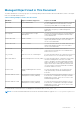
Managed Object Used in This Document The MIB is divided into several major groups. The following table provides information about the MIB names, name of the agent that uses each MIB and the purpose: Table 2. Managed Object Used in This Document MIB Name Agent / Hardware Supported Purpose of the MIB 10892.mib Server Administrator Provides the information about the systems monitored by Server Administrator instrumentation software. This is the primary MIB for PowerEdge systems. dcs3fru.
Server Administrator Instrumentation MIB The Server Administrator Instrumentation MIB ( filename 10892.mib ) provides instrumentation data that allows you to monitor the health of a system with SNMP management applications.
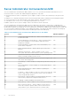
Table 3. Server Administrator Instrumentation MIB Sections in This Guide (continued) Section Topics MIB Group Numbers 17 Local Response Agent Group — defines variables for global settings and actions.
Table 4. Server Administrator Storage Management MIB Sections in This Guide (continued) Section Topics MIB Group Numbers 27 Storage Management Alert Reference — lets you monitor the health of NA storage resources such as controllers, connectors, array disks, and virtual disks Server Administrator Field Replaceable Unit MIB The Server Administrator Field Replaceable Unit MIB (filename dcs3fru.mib) provides information about field replaceable unit (FRU) hardware that may be present in your system.
Settings are the conditions of a manageable object that determine what happens when a certain value is detected in a component. For example, a user can set the upper critical threshold of a temperature probe to 75 degrees Celsius. If the probe reaches that temperature, the setting causes an alert to be sent to the management console. Some settings, when reached, can trigger a system shutdown or other response to prevent damage to the system.
Table 9. UUID Chassis Index (continued) Description Defines the index (one-based) of this chassis. Syntax DellObjectRange Access Read-only Table 10. UUID Index Name uUIDIndex Object ID 1.3.6.1.4.1.674.10892.1.300.20.1.2 Description Defines the index of the UUID in a specified chassis. Syntax DellObjectRange Access Read-only Table 11. UUID Type Name uUIDType Object ID 1.3.6.1.4.1.674.10892.1.300.20.1.3 Description Defines the type of the UUID for this chassis.
4. BIOS Variable Values — This section explains any Server Administrator-specific variables and data types that are used in this section. In the BIOS group example, there are 17 unique, Server Administrator-specific variable meanings. Information on each Server Administrator-specific variable is presented in a formatted table. Other Documents You May Need In addition to this guide, you can access the following guides available on the Dell Support website at dell.com/support/ manuals.
Management Information Base Object Identifiers Each data class within a Management Information Base (MIB) is defined by an Object Identifier (OID). OIDs are unique across all MIBs. An OID consists of a series of digits separated by periods. The OID functions in a similar fashion to a phone number. The phone number 011-512-471-0000 uniquely identifies a single phone. The phone number can be broken down into a number of components to uniquely identify a phone.
SNMP Traps SNMP is frequently used to monitor systems for fault conditions such as temperature violations, hard drive failures. Management applications can monitor for these conditions by polling the appropriate OIDs with the Get command and analyzing the returned data. This method has its drawbacks. If it is done frequently, significant amounts of network bandwidth can be consumed. If it is done infrequently, the response to the fault condition may not occur in a timely fashion.
2 Server Administrator Group The Server Administrator group comprises of the following sections: ● ● ● ● ● ● ● ● ● ● ● ● ● ● ● ● ● ● ● Instrumentation MIB Version Group Systems Management Software Group System State Group Chassis Information Group Operating System Group System Resource Group Power Group Thermal Group Remote Flash BIOS Group Port Group Device Group Slot Group Memory Group BIOS Setup Control Group Local Response Agent Group Cost of Ownership Group Cluster Group Baseboard Management Controlle
Management Information Base Major Version Number Table 14. Management Information Base Major Version Number Name mIBMajorVersionNumber Object ID 1.3.6.1.4.1.674.10892.1.1.1.0 Description Defines the major version number of the version of this MIB supported by the systems management software. For example, if the MIB version is 1.2.3, the major version number is 1. A major version number change indicates a major change in object functionality.
NOTE: Using the Software > Server Preferences menu of Server Administrator, you can bind to either one IP address or to all IP addresses.
Table 21. Systems Management Software Supported Protocol (continued) Description Defines the systems management standards (SNMP or CIM) supported by the systems management software. Syntax SMSSupportedTypes (Systems Management Software Supported Standards) Access Read-only Table 22. Systems Management Software Preferred Protocol Name systemManagementSoftwarePreferredProtocol Object ID 1.3.6.1.4.1.674.10892.1.100.
Table 27. Systems Management Software Feature Flags (continued) Object ID 1.3.6.1.4.1.674.10892.1.100.11 Description Defines the features of the systems management software. Syntax SMSFeatureFlags (Systems Management Software Feature Flags) Access Read-only Table 28. Systems Management Software SNMP Agent Feature Flags Name systemManagementSoftwareSNMPAgentFeatureFlags Object ID 1.3.6.1.4.1.674.10892.1.100.
Table 32. Systems Management Software SNMP Agent Feature Flags Variable Name: SMSSNMPAgentFeatureFlags Data Type: Integer Possible Data Values Meaning of Data Value none(0) The Systems Management Software SNMP agent features are not enabled. supportsSparseTables(1) The SNMP agent supports sparse tables.
● systemStateSDCardUnitStatusCombined ● systemStateSDCardDeviceStatusCombined List 2 Variables that provide health status of each component in associated subsystem in chassis: ● ● ● ● ● ● ● ● ● ● ● ● ● ● ● ● systemStatePowerSupplyStatusDetails systemStateVoltageStatusDetails systemStateAmperageStatusDetails systemStateCoolingDeviceStatusDetails systemStateTemperatureStatusDetails systemStateMemoryDeviceStatusDetails systemStateChassisIntrusionStatusDetails systemStateACPowerCordStatusDetails systemStatePo
Table 36. System State Global System Status Name systemStateGlobalSystemStatus Object ID 1.3.6.1.4.1.674.10892.1.200.10.1.2 Description Defines the global system status of all chassis being monitored by this instrumentation instance. Syntax DellStatus Access Read-only Table 37. System State Chassis State Name systemStateChassisState Object ID 1.3.6.1.4.1.674.10892.1.200.10.1.3 Description Defines the system state of this chassis. Syntax DellStateSettings Access Read-only Table 38.
Table 41. System State Power Unit Status Details (continued) unit. The first byte returned represents the status of the first power unit, the second byte returned represents the status of the second power unit, and so on. The bytes have the same definition type as DellStatusRedundancy. Syntax Octet String Access Read-only Table 42. System State Power Supply State Details Name systemStatePowerSupplyStateDetails Object ID 1.3.6.1.4.1.674.10892.1.200.10.1.
Table 46. System State Voltage Status Combined Name systemStateVoltageStatusCombined Object ID 1.3.6.1.4.1.674.10892.1.200.10.1.12 Description Defines the status of all voltage probes in this chassis. Syntax DellStatus Access Read-only Table 47. System State Voltage Status Details Name systemStateVoltageStatusDetails Object ID 1.3.6.1.4.1.674.10892.1.200.10.1.13 Description Defines the status of all voltage probes in this chassis. Syntax Octet String Access Read-only Table 48.
Table 51. System State Cooling Unit State Details (continued) Object ID 1.3.6.1.4.1.674.10892.1.200.10.1.17 Description Defines the state of all cooling units in this chassis. The results are returned as a binary octet string. Each byte of the octet string represents the state of a specific cooling unit. The first byte returned represents the state of the first cooling unit, the second byte returned represents the state of the second cooling unit, and so on.
Table 56. System State Cooling Device Status Details Name systemStateCoolingDeviceStatusDetails Object ID 1.3.6.1.4.1.674.10892.1.200.10.1.22 Description Defines the status of all cooling devices in this chassis. The results are returned as a binary octet string. Each byte of the octet string represents the status of a specific cooling device.
Table 60. System State Memory Device State Details (continued) Syntax Octet String Access Read-only Table 61. System State Memory Device Status Combined Name systemStateMemoryDeviceStatusCombined Object ID 1.3.6.1.4.1.674.10892.1.200.10.1.27 Description Defines the status of all memory devices in this chassis. Syntax DellStatus Access Read-only Table 62. System State Memory Device Status Details Name systemStateMemoryDeviceStatusDetails Object ID 1.3.6.1.4.1.674.10892.1.200.10.1.
Table 65. System State Chassis Intrusion Status Details (continued) Description Defines the intrusion status of all intrusion detection devices in this chassis. The first byte returned represents the status of the first intrusion detection device, the second byte returned represents the status of the second intrusion detection device, and so on. Syntax Octet String Access Read-only Table 66. System State AC Power Switch State Details Name systemStateACPowerSwitchStateDetails Object ID 1.3.6.1.4.1.
Table 70. System State AC Power Cord Status Combined (continued) Syntax DellStatus Access Read-only Table 71. System State AC Power Cord Status Details Name systemStateACPowerCordStatusDetails Object ID 1.3.6.1.4.1.674.10892.1.200.10.1.37 Description Defines the individual status of all AC power cords for any AC power switches in this chassis.
Table 75. System State Event Log Status (continued) Access Read-only Table 76. System State Power Unit Status Combined Name systemStatePowerUnitStatusCombined Object ID 1.3.6.1.4.1.674.10892.1.200.10.1.42 Description Defines the combined status of all power units of this chassis. Syntax DellStatus Access Read-only Table 77. System State Power Unit Status List Name systemStatePowerUnitStatusList Object ID 1.3.6.1.4.1.674.10892.1.200.10.1.
Table 81. System State AC Power Switch Status List Name systemStateACPowerSwitchStatusList Object ID 1.3.6.1.4.1.674.10892.1.200.10.1.47 Description Lists the status of each AC power switch of this chassis. The results are returned as a binary octet string where each byte of the octet string represents the status of an AC power switch. The first byte returned represents the status of the first AC power switch, and so on. The bytes have the same definition type as DellStatus.
Table 86. System State Battery Status Combined Name systemStateBatteryStatusCombined Object ID 1.3.6.1.4.1.674.10892.1.200.10.1.52 Description Defines the combined status of all batteries of this chassis. Syntax DellStatus Access Read-only Table 87. System State Battery Status List Name systemStateBatteryStatusList Object ID 1.3.6.1.4.1.674.10892.1.200.10.1.53 Description Lists the status of each battery of this chassis.
Table 91. System State SD Card Device Status List (continued) Description Lists the status of each SD Card device of this chassis. The results are returned as a binary octet string where each byte of the octet string represents the status of a SD Card device. The first byte returned represents the status of the first SD Card device, and so on. The bytes have the same definition type as DellStatus.
Table 94. Chassis Index Chassis Information (continued) Object ID 1.3.6.1.4.1.674.10892.1.300.10.1.1 Description Defines the index (one-based) of this chassis. The first chassis is numbered one. Syntax DellObjectRange Access Read-only Table 95. Chassis State Capabilities Name chassisStateCapabilities Object ID 1.3.6.1.4.1.674.10892.1.300.10.1.2 Description Defines the capabilities of the chassis. Syntax DellStateCapabilities Access Read-only Table 96.
Table 100. Chassis Name Name chassisName Object ID 1.3.6.1.4.1.674.10892.1.300.10.1.7 Description Defines the user-assigned chassis name of the chassis. Syntax DellString Access Read-only Table 101. Chassis Manufacturer Name Name chassisManufacturerName Object ID 1.3.6.1.4.1.674.10892.1.300.10.1.8 Description Defines the manufacturer’s name for this chassis. Syntax DellString Access Read-only Table 102. Chassis Model Name Name chassisModelName Object ID 1.3.6.1.4.1.674.10892.1.300.10.
Table 106. Chassis ID Extension Name chassisIDExtension Object ID 1.3.6.1.4.1.674.10892.1.300.10.1.13 Description Defines the SMBIOS machine ID of this chassis. Syntax DellUnsigned16BitRange Access Read-only Table 107. Chassis System Class Name chassisSystemClass Object ID 1.3.6.1.4.1.674.10892.1.300.10.1.14 Description Defines the chassis class of this chassis. Syntax DellChassisSystemClass (See Chassis Type) Access Read-only Table 108.
Table 112. Chassis System Primary User Name Name chassisSystemPrimaryUserName Object ID 1.3.6.1.4.1.674.10892.1.300.10.1.19 Description Defines the user-assigned primary user name for this chassis. Syntax DellString Access Read-only Table 113. Chassis System User Phone Number Name Name chassisSystemUserPhoneNumberName Object ID 1.3.6.1.4.1.674.10892.1.300.10.1.20 Description Defines the user-assigned phone number of the primary user of the system.
Table 118. Chassis LED Control Settings Unique Name chassisLEDControlSettingsUnique Object ID 1.3.6.1.4.1.674.10892.1.300.10.1.25 Description Defines the readings and settings of the LED control hardware in the chassis. Syntax DellLEDControlSettings (See Front-Panel LED Control Settings) Access Read-only Table 119. Chassis Hard-Drive (HD) Fault Clear Control Capabilities Name chassisHDFaultClearControlCapabilities Object ID 1.3.6.1.4.1.674.10892.1.300.10.1.
Table 124. Chassis Host Control Capabilities Unique Name chassishostControlCapabilitiesUnique Object ID 1.3.6.1.4.1.674.10892.1.300.10.1.31 Description Defines the capabilities of the host control object. Syntax DellHostControlCapabilities (See Host Control Capabilities) Access Read-only Table 125. Chassis Host Control Settings Unique Name chassishostControlSettingsUnique Object ID 1.3.6.1.4.1.674.10892.1.300.10.1.32 Description Defines the current settings of the host control object.
Table 130. Chassis Allow Set Commands From SNMP Name chassisallowSETCommandsfromSNMP Object ID 1.3.6.1.4.1.674.10892.1.300.10.1.37 Description Specifies whether Simple Network Management Protocol (SNMP) Set type commands are allowed by Server Administrator. This attribute does not reflect whether SNMP Set type commands are allowed by the SNMP master agent. Syntax DellBoolean Access Read-only Table 131.
Table 136. Chassis Reseller System ID Name chassisResellerSystemID Object ID 1.3.6.1.4.1.674.10892.1.300.10.1.43 Description Defines the chassis reseller system ID. Syntax DellUnsigned16BitRange Access Read-only Table 137. Chassis NMI Button Control Capabilities Unique Name chassisNMIButtonControlCapabilitiesUnique Object ID 1.3.6.1.4.1.674.10892.1.300.10.1.44 Description Defines the capabilities of the NMI button control function.
Table 142. Chassis Express Service Code Name Name chassisExpressServiceCodeName Object ID 1.3.6.1.4.1.674.10892.1.300.10.1.49 Description Defines the express service code of the chassis. Syntax DellString Access Read-only Table 143. Chassis Node ID Name chassisNodeIDName Object ID 1.3.6.1.4.1.674.10892.1.300.10.1.50 Description Defines the NodeID of the chassis.
Table 147. UUID Index Name uUIDIndex Object ID 1.3.6.1.4.1.674.10892.1.300.20.1.2 Description Defines the index of the UUID in a specified chassis. Syntax DellObjectRange Access Read-only Table 148. UUID Type Name uUIDType Object ID 1.3.6.1.4.1.674.10892.1.300.20.1.3 Description Defines the type of the UUID for this chassis. Syntax DellUUIDType Access Read-only Table 149. UUID Value Name uUIDValue Object ID 1.3.6.1.4.1.674.10892.1.300.20.1.
Table 151. POST Log Table Entry (continued) , postLogRecordIndex Table 152. POST Log Chassis Index Name postLogchassisIndex Object ID 1.3.6.1.4.1.674.10892.1.300.30.1.1 Description Defines the index (one-based) of this chassis. Syntax DellObjectRange Access Read-only Table 153. POST Log Record Index Name postLogRecordIndex Object ID 1.3.6.1.4.1.674.10892.1.300.30.1.2 Description Defines the record number (one-based) of the POST log.
Table 157. POST Log Format (continued) Description Defines format of the POST log. Syntax DellLogFormat (See Log Format) Access Read-only Event Log Table Table 158. Event Log Table Name eventLogTableEntry Object ID 1.3.6.1.4.1.674.10892.1.300.40 Description Defines the Event Log Table. Syntax SEQUENCE OF EventLogTableEntry Access Not accessible Table 159. Event Log Table Entry Name eventLogTableEntry Object ID 1.3.6.1.4.1.674.10892.1.300.40.
Table 162. Event Log State Capabilities Unique (continued) Description Defines the capabilities of the object that is writing the event log. Syntax DellStateCapabilitiesLogUnique Access Read-only Table 163. Event Log State Settings Unique Name eventLogStateSettingsUnique Object ID 1.3.6.1.4.1.674.10892.1.300.40.1.4 Description Defines the state settings for the object that is writing the event log. Syntax DellStateSettingsLogUnique Access Read-only Table 164.
System BIOS Table This table lists objects that define the system’s basic input/output system (BIOS). Table 168. System BIOS Table Name systemBIOSTable Object ID 1.3.6.1.4.1.674.10892.1.300.50 Description Defines the System BIOS Table. Syntax SEQUENCE OF SystemBIOSTableEntry Access Not accessible Table 169. System BIOS Table Entry Name systemBIOSTableEntry Object ID 1.3.6.1.4.1.674.10892.1.300.50.1 Description Defines the System BIOS Table entry.
Table 173. System BIOS State Settings Name systemBIOSStateSettings Object ID 1.3.6.1.4.1.674.10892.1.300.50.1.4 Description Defines the state of the system BIOS of this object. Syntax DellStateSettings Access Read-only Table 174. System BIOS Status Name systemBIOSStatus Object ID 1.3.6.1.4.1.674.10892.1.300.50.1.5 Description Defines the status of the system BIOS of this object. Syntax DellStatus Access Read-only Table 175. System BIOS Size Name systemBIOSSize Object ID 1.3.6.1.4.1.
Table 179. System BIOS Ending Address Name systemBIOSEndingAddress Object ID 1.3.6.1.4.1.674.10892.1.300.50.1.10 Description Defines the ending address of the system BIOS. A zero (0) indicates that the address is unknown. Syntax DellUnsigned64BitRange Access Read-only Table 180. System BIOS Manufacturer Name Name systemBIOSManufacturerName Object ID 1.3.6.1.4.1.674.10892.1.300.50.1.11 Description Defines the system BIOS manufacturer’s name. Syntax DellString Access Read-only Table 181.
Table 181. System BIOS Characteristics (continued) ● ● ● ● ● ● ● ● ● ● ● ● ● ● ● Syntax Bit Bit Bit Bit Bit Bit Bit Bit Bit Bit Bit Bit Bit Bit Bit 24 - Int 13h - 3.5 in / 720 KB Floppy Services are supported 25 - Int 13h - 3.5 in / 2.
Firmware Table Table 184. Firmware Table Name firmwareTable Object ID 1.3.6.1.4.1.674.10892.1.300.60 Description Defines the Firmware Table. Syntax SEQUENCE OF FirmwareTableEntry Access Not accessible Table 185. Firmware Table Entry Name firmwareTableEntry Object ID 1.3.6.1.4.1.674.10892.1.300.60.1 Description Defines the Firmware Table entry Syntax FirmwareTableEntry Access Not accessible Index firmwarechassisIndex , firmwareIndex Table 186.
Table 189. Firmware State Capabilities Name firmwareStateCapabilities Object ID 1.3.6.1.4.1.674.10892.1.300.60.1.4 Description Defines the state of the firmware and allows for the setting of the firmware. Syntax DellStateCapabilities Access Read-only Table 190. Firmware Status Name firmwareStatus Object ID 1.3.6.1.4.1.674.10892.1.300.60.1.5 Description Defines the status of the firmware. Syntax DellStateSettings Access Read-only Table 191. Firmware Size Name firmwareSize Object ID 1.
Table 195. Firmware Date Name Name firmwareDateName Object ID 1.3.6.1.4.1.674.10892.1.300.60.1.10 Description Defines the date of the firmware. Syntax DellDateName Access Read-only Table 196. Firmware Version Name Name firmwareVersionName Object ID 1.3.6.1.4.1.674.10892.1.300.60.1.11 Description Defines the version name of the firmware.
Table 199. Intrusion Chassis Index (continued) Syntax DellObjectRange Access Read-only Table 200. Intrusion Index Name intrusionIndex Object ID 1.3.6.1.4.1.674.10892.1.300.70.1.2 Description Defines the index of the intrusion objects and drive bay object in this subgroup. Syntax DellObjectRange Access Read-only Table 201. Intrusion State Capabilities Name intrusionStateCapabilities Object ID 1.3.6.1.4.1.674.10892.1.300.70.1.
Table 205. Intrusion Type (continued) Syntax DellIntrusionType Access Read-only Table 206. Intrusion Location Name Name intrusionLocationName Object ID 1.3.6.1.4.1.674.10892.1.300.70.1.8 Description This attribute defines the location of the intrusion and drive bay sensor. Syntax DellString Access Read-only Baseboard Table This table lists objects that define the baseboard of a system. Table 207. Baseboard Table Name baseBoardTable Object ID 1.3.6.1.4.1.674.10892.1.300.
Table 210. Baseboard Index (continued) Description Defines the index (one-based) of the base board. Syntax DellObjectRange Access Read-only Table 211. Baseboard State Capabilities Name baseBoardStateCapabilities Object ID 1.3.6.1.4.1.674.10892.1.300.80.1.3 Description Defines the state capabilities of the baseboard. Syntax DellStateCapabilities Access Read-only Table 212. Baseboard State Settings Name baseBoardStateSettings Object ID 1.3.6.1.4.1.674.10892.1.300.80.1.
Table 216. Baseboard Type Name (continued) Description Defines the name of the type of baseboard. Syntax DellString Access Read-only Table 217. Baseboard Location Name Name baseBoardLocationName Object ID 1.3.6.1.4.1.674.10892.1.300.80.1.9 Description Defines the location name of the baseboard. Syntax DellString Access Read-only Table 218. Baseboard Manufacturer Name Name baseBoardManufacturerName Object ID 1.3.6.1.4.1.674.10892.1.300.80.1.
Table 222. Baseboard Piece Part ID (PPID) Name (continued) Description Defines the baseboard PPID. Syntax DellString Access Read-only Table 223. Baseboard Asset Tag Name Name baseBoardAssetTagName Object ID 1.3.6.1.4.1.674.10892.1.300.80.1.15 Description Defines the baseboard asset tag name. Syntax DellString Access Read-only Table 224. Baseboard Express Service Code Name Name baseBoardExpressServiceCodeName Object ID 1.3.6.1.4.1.674.10892.1.300.80.1.
Table 226. Chassis Type (continued) tower(7) The chassis type is a tower. portable(8) The chassis type is a portable. lapTop(9) The chassis type is a laptop. noteBook(10) The chassis type is a notebook. handHeld(11) The chassis type is a handheld. dockingStation(12) The chassis type is a docking station. allInOne(13) The chassis type is an all-in-one. subNoteBook(14) The chassis type is a subnotebook. spaceSaving(15) The chassis type is a spacesaver.
Table 228. Fan Control Capabilities (continued) lowOrhighSpeedCapab The fan can be set to low or high speed. le(6) Table 229. Front-Panel LED Control Capabilities Variable Name : DellLEDControlCapabilities Data Type: Integer Possible Data Values Meaning of Data Value unknown(1) The LED control capabilities are unknown. alertOnErrorCapable The LED control can be set to alert on an error (2) condition.
Table 232. Hard-Drive Fault LED Control Settings (continued) enabled(2) The hard-drive fault LEDs’ state is disabled (offline, a binary 0 value) or enabled (online, a binary 1 value). notReady(4) The hard-drive fault LEDs’ state is not ready. reset(8) The hard-drive fault LEDs have been reset. resetAndEnable(10) The hard-drive fault LEDs have been reset and enabled. Table 233.
Table 235. Host Control Capabilities (continued) Data Type: Integer Possible Data Values Meaning of Data Value manualRebootCapabl e(1) The operator can reboot capable host. manualPowerOFFCapa ble(2) The operator can power off capable host. manualPowerCycleCa pable(4) The operator can power-cycle capable host. manualAllExceptOpe rating SystemShutdownCapa ble(7) The operator can reboot and power off capable host.
Table 236. Host Control Settings (continued) manualOperatingSys temShutdown(8) The operator can shut down the operating system on the host. manualOperatingSys temShutdownThe nPowerCycle(12) The operator can shut down the operating system on the host then power cycle machine. Table 237.
Table 239. Watchdog Timer Capabilities (continued) Data Type: Integer Possible Data Values Meaning of Data Value type1Capable(1) Watchdog timer can time in intervals from 20–480 seconds. type2Capable(2) Watchdog timer can time in 30-, 60-, 120-, and 480second intervals. type3Capable(4) Watchdog timer can time in 60-second intervals. Table 240.
Table 243. System Properties (continued) none(0) No properties. energySmart(1) The system is an Energy Smart System. Table 244. NMI Button Control Settings Variable Name : DellNMIButtonControlSettings Data Type: Integer Possible Data Values Meaning of Data Value none(0) The NMI button has no settings capabilities. unknown(1) The NMI button settings are unknown. enabled(2) The NMI button state is enabled. disabled(4) The NMI button state is disabled. Table 245.
Table 246. Chassis System Class (continued) workstationClass(3 ) The chassis system class is a workstation. serverClass(4) The chassis system class is a server. desktopClass(5) The chassis system class is a desktop. portableClass(6) The chassis system class is a portable. netPCClass(7) The chassis system class is a Net PC. storageClass(8) The chassis system class is storage. Table 247.
Table 247. Firmware Type (continued) iDRAC7(21) The firmware type is Integrated Dell Remote Access Controller 7. iDRAC8(22) The firmware type is Integrated Dell Remote Access Controller 8. iDRAC9(23) The firmware type is Integrated Dell Remote Access Controller 9. Table 248. Intrusion Reading Variable Name : DellIntrusionReading Data Type: Integer Possible Data Values Meaning of Data Value chassisNotBreached(1) The chassis is not breached and no uncleared breaches.
Table 250. Baseboard Feature Flags (continued) boardIsHotSwappabl e(16) This baseboard is hot swappable. Operating System Group The Operating System Group provides status and identifying information about a system’s operating system. Identifying information includes the name, version, service pack, and patch level of the installed operating system. Operating System Memory Table Table 251. Operating System Memory Table Name operatingSystemMemoryTable Object ID 1.3.6.1.4.1.674.10892.1.400.
Table 255. Operating System Memory State Settings (continued) Description Defines the state and allows the setting of the operating system memory. Syntax DellStateSettings Access Read-only Table 256. Operating System Memory Status Name operatingSystemMemoryStatus Object ID 1.3.6.1.4.1.674.10892.1.400.20.1.4 Description Defines the status of the operating system memory. Syntax DellStatus Access Read-only Table 257.
Table 261. Operating System Memory Total Virtual Size Name operatingSystemMemoryTotalVirtualSize Object ID 1.3.6.1.4.1.674.10892.1.400.20.1.9 Description Defines the total virtual memory size in kilobytes. Syntax DellUnsigned32BitRange Access Read-only Table 262. Operating System Memory Available Virtual Size Name operatingSystemMemoryAvailableVirtualSize Object ID 1.3.6.1.4.1.674.10892.1.400.20.1.10 Description Defines the available virtual memory size in kilobytes.
Table 264. System Resource Map Table (continued) Description Defines the System Resource Map Table. Syntax SEQUENCE OF SystemResourceMapTableEntry Access Not accessible Table 265. System Resource Map Table Entry Name systemResourceMapTableEntry Object ID 1.3.6.1.4.1.674.10892.1.500.10.1 Description Defines the System Resource Map Table entry. Syntax SystemResourceMapTableEntry Access Not accessible Index systemResourceMapchassisIndex , systemResourceMapIndex Table 266.
Table 269. System Resource Map State Settings (continued) Access Read-only Table 270. System Resource Map Status Name systemResourceMapStatus Object ID 1.3.6.1.4.1.674.10892.1.500.10.1.5 Description Defines the status of this system map. Syntax DellStatus Access Read-only Table 271. System Resource Map Type Name systemResourceMapType Object ID 1.3.6.1.4.1.674.10892.1.500.10.1.6 Description Defines the type of this system map.
Table 274. System Resource Owner Chassis Index (continued) Syntax DellObjectRange Access Read-only Table 275. System Resource Owner Index Name systemResourceOwnerIndex Object ID 1.3.6.1.4.1.674.10892.1.500.20.1.2 Description Defines the index of system resource owners for this chassis. Syntax DellObjectRange Access Read-only Table 276. System Resource Owner State Capabilities Name systemResourceOwnerStateCapabilities Object ID 1.3.6.1.4.1.674.10892.1.500.20.1.
Table 280. System Resource Map Index Reference (continued) Syntax DellObjectRange Access Read-only Table 281. System Resource Owner Description Name Name systemResourceOwnerDescriptionName Object ID 1.3.6.1.4.1.674.10892.1.500.20.1.8 Description Defines the description name of the system resource owner. Syntax DellString Access Read-only Table 282. System Resource Owner Interface Instance Name systemResourceOwnerInterfaceInstance Object ID 1.3.6.1.4.1.674.10892.1.500.20.1.
Table 285. System Resource I/O Port Chassis Index (continued) Syntax DellObjectRange Access Read-only Table 286. System Resource I/O Port Index Name systemResourceIOPortIndex Object ID 1.3.6.1.4.1.674.10892.1.500.30.1.2 Description Defines the index (one-based) of the system resource I/O ports in this chassis. Syntax DellObjectRange Access Read-only Table 287. System Resource I/O Port State Capabilities Name systemResourceIOPortStateCapabilities Object ID 1.3.6.1.4.1.674.10892.1.500.30.1.
Table 291. System Resource I/O Port Share Disposition (continued) Syntax DellResourceShareDisposition (Resource Share Disposition) Access Read-only Table 292. System Resource I/O Port Starting Address Name systemResourceIOPortStartingAddress Object ID 1.3.6.1.4.1.674.10892.1.500.30.1.8 Description Defines the 64 bits of the starting address of the system resource I/O port. Syntax DellUnsigned64BitRange Access Read-only Table 293.
Table 296. System Resource Memory Chassis Index (continued) Syntax DellObjectRange Access Read-only Table 297. System Resource Memory Index Name systemResourceMemoryIndex Object ID 1.3.6.1.4.1.674.10892.1.500.40.1.2 Description Defines the index of system resource memory in this chassis. Syntax DellObjectRange Access Read-only Table 298. System Resource Memory State Capabilities Name systemResourceMemoryStateCapabilities Object ID 1.3.6.1.4.1.674.10892.1.500.40.1.
Table 302. System Resource Memory Share Disposition (continued) Syntax DellResourceShareDisposition (Resource Share Disposition) Access Read-only Table 303. System Resource Memory Starting Address Name systemResourceMemoryStartingAddress Object ID 1.3.6.1.4.1.674.10892.1.500.40.1.8 Description Defines the 64 bits of the starting address of the system resource memory. Syntax DellUnsigned64BitRange Access Read-only Table 304.
Table 307. System Resource Interrupt Table Entry (continued) , systemResourceInterruptIndex Table 308. System Resource Interrupt Chassis Index Name systemResourceInterruptchassisIndex Object ID 1.3.6.1.4.1.674.10892.1.500.50.1.1 Description Defines the index (one-based) of this chassis. Syntax DellObjectRange Access Not accessible Table 309. System Resource Interrupt Index Name systemResourceInterruptIndex Object ID 1.3.6.1.4.1.674.10892.1.500.50.1.
Table 313. System Resource Interrupt Owner Index Reference (continued) Description Defines the index for the associated system resource owner in this chassis. Syntax DellObjectRange Access Read-only Table 314. System Resource Interrupt Owner Share Disposition Name systemResourceInterruptShareDisposition Object ID 1.3.6.1.4.1.674.10892.1.500.50.1.7 Description Defines the share disposition of the system resource interrupt.
Table 319. System Resource DMA Table Entry Name systemResourceDMATable Object ID 1.3.6.1.4.1.674.10892.1.500.60.1 Description Defines the System Resource DMA Table entry. Syntax SystemResourceDMATableEntry Access Not accessible Index systemResourceDMAchassisIndex , systemResourceDMAIndex Table 320. System Resource DMA Chassis Index Name systemResourceDMAchassisIndex Object ID 1.3.6.1.4.1.674.10892.1.500.60.1.1 Description Defines the index (one-based) of this chassis.
Table 324. System Resource DMA Status (continued) Description Defines the status of this system resource DMA. Syntax DellStatus Access Read-only Table 325. System Resource DMA Owner Index Reference Name systemResourceDMAOwnerIndexReference Object ID 1.3.6.1.4.1.674.10892.1.500.60.1.6 Description Defines the index to the associated system resource owner in this chassis. Syntax DellObjectRange Access Read-only Table 326.
Table 330. System Resource Map Type Variable Name: DellSystemResourceMapType Data Type: Integer Possible Data Values Meaning of Data Value other(1) The system resource map type is not one of the following: unknown(2) The system resource map type is unknown (not known or not monitored). typeOne(3) The system resource map is type 1 (one). Table 331.
Table 334. Resource Interrupt Type Variable Name: DellResourceInterruptType Data Type: Integer Possible Data Values Meaning of Data Value interruptIsLevelSensitive( The interrupt type is level sensitive. 1) interruptIsLatched(2) The interrupt type is latched. Table 335. Resource Interrupt Trigger Variable Name: DellResourceInterruptTrigger Data Type: Integer Possible Data Values Meaning of Data Value interruptIsActiveWhenLow(1 The interrupt trigger is active on a low signal.
Power Group The Power Group provides information about power units (a group of power supplies in a system chassis), power supplies, and voltage and amperage probes. NOTE: Power Management features are only available for PowerEdge systems that have hot-swappable power supplies and not systems that have a fixed, nonredundant power supply installed.
Table 341. Power Unit Index (continued) Object ID 1.3.6.1.4.1.674.10892.1.600.10.1.2 Description Defines the index of the power unit in this chassis. Syntax DellObjectRange Access Read-only Table 342. Power Unit State Capabilities Name powerUnitStateCapabilities Object ID 1.3.6.1.4.1.674.10892.1.600.10.1.3 Description Defines the capabilities of the power unit. Syntax DellStateCapabilities Access Read-only Table 343. Power Unit State Settings Name powerUnitStateSettings Object ID 1.3.6.
Table 347. Power Unit Status Name powerUnitStatus Object ID 1.3.6.1.4.1.674.10892.1.600.10.1.8 Description Defines the status of the power unit in this chassis. Syntax DellStatus Access Read-only Power Supply Table Table 348. Power Supply Table Name powerSupplyTable Object ID 1.3.6.1.4.1.674.10892.1.600.12 Description Defines the Power Supply Table. Syntax PowerSupplyTableEntry Access Not accessible Table 349. Power Supply Table Entry Name powerSupplyTableEntry Object ID 1.3.6.1.4.1.
Table 352. Power Supply State Capabilities Unique (continued) Syntax DellPowerSupplyStateCapabilitiesUnique (Power Supply State Capabilities Unique) Access Read-only Table 353. Power Supply State Settings Unique Name powerSupplyStateSettingsUnique Object ID 1.3.6.1.4.1.674.10892.1.600.12.1.4 Description Defines the state and settings of the power supply. Syntax DellPowerSupplyStateSettingsUnique (Power Supply State Settings Unique) Access Read-only Table 354.
Table 358. Power Supply Maximum Input Voltage (continued) Syntax DellSigned32BitRange Access Read-only Table 359. Power Supply Power Unit Index Reference Name powerSupplypowerUnitIndexReference Object ID 1.3.6.1.4.1.674.10892.1.600.12.1.10 Description Defines the index to the associated system power unit in this chassis. Syntax DellObjectRange Access Read-only Table 360. Power Supply Sensor State Name powerSupplySensorState Object ID 1.3.6.1.4.1.674.10892.1.600.12.1.
Table 364. Power Supply FQDD (continued) Description Fully qualified device descriptor (FQDD) of the power supply. Syntax FQDDString Access Read-only Table 365. Power Supply Current Input Voltage Name powerSupplyCurrentInputVoltage Object ID 1.3.6.1.4.1.674.10892.1.600.12.1.16 Description This attribute defines the current input voltage to the power supply (in Volts). Syntax DellSigned32BitRange Access Read-only Voltage Probe Table Table 366.
Table 370. Voltage Probe State Capabilities Name voltageProbeStateCapabilities Object ID 1.3.6.1.4.1.674.10892.1.600.20.1.3 Description Defines the capabilities of the voltage probe. Syntax DellStateCapabilities Access Read-only Table 371. Voltage Probe State Settings Name voltageProbeStateSettings Object ID 1.3.6.1.4.1.674.10892.1.600.20.1.4 Description Defines the state and settings of the voltage probe. Syntax DellStateSettings Access Read-only Table 372.
Table 376. Voltage Probe Upper Nonrecoverable Threshold Name voltageProbeUpperNonRecoverableThreshold Object ID 1.3.6.1.4.1.674.10892.1.600.20.1.9 Description Defines the value of the voltage probe’s upper nonrecoverable threshold. Syntax DellSigned32BitRange Access Read-only Table 377. Voltage Probe Upper Critical Threshold Name voltageProbeUpperCriticalThreshold Object ID 1.3.6.1.4.1.674.10892.1.600.20.1.10 Description Defines the value of the voltage probe’s upper critical threshold.
Table 382. Voltage Probe Capabilities Name voltageProbeProbeCapabilities Object ID 1.3.6.1.4.1.674.10892.1.600.20.1.15 Description Defines the probe capabilities of the voltage probe. Syntax DellProbeCapabilities Access Read-only Table 383. Voltage Probe Discrete Reading Name voltageProbeDiscreteReading Object ID 1.3.6.1.4.1.674.10892.1.600.20.1.16 Description Defines the reading for a voltage probe of type voltageProbeTypeIsDiscrete.
Table 386. Amperage Probe Chassis Index (continued) Syntax DellObjectRange Access Read-only Table 387. Amperage Probe Index Name amperageProbeIndex Object ID 1.3.6.1.4.1.674.10892.1.600.30.1.2 Description Defines the index of amperage probes in this chassis. Syntax DellObjectRange Access Read-only Table 388. Amperage Probe State Capabilities Name amperageProbeStateCapabilities Object ID 1.3.6.1.4.1.674.10892.1.600.30.1.3 Description Defines the capabilities of the amperage probe.
Table 391. Amperage Probe Reading (continued) When the value for amperageProbeType is other than amperageProbeTypeIsDiscrete, amperageProbeTypeIsPowerSupplyAmps, amperageProbeTypeIsPowerSupplyWatts, amperageProbeTypeIsSystemAmps, or amperageProbeTypeIsSystemWatts, the value returned for this attribute is the amperage that the probe is reading in Milliamps. When the value for amperageProbeType is amperageProbeTypeIsDiscrete, a value is not returned for this attribute.
Table 396. Amperage Probe Upper Noncritical Threshold (continued) Access Read-only Table 397. Amperage Probe Lower Noncritical Threshold Name amperageProbeLowerNonCriticalThreshold Object ID 1.3.6.1.4.1.674.10892.1.600.30.1.12 Description Defines the user-assigned value of the amperage probe’s lower noncritical threshold. Syntax DellSigned32BitRange Access Read-only Table 398. Amperage Probe Lower Critical Threshold Name amperageProbeLowerCriticalThreshold Object ID 1.3.6.1.4.1.674.10892.1.
AC Power Switch Table Table 402. AC Power Switch Table Name aCPowerSwitchTable Object ID 1.3.6.1.4.1.674.10892.1.600.40 Description Defines the AC Power Switch Table. Syntax SEQUENCE OF ACPowerSwitchTableEntry Access Not accessible Table 403. AC Power Switch Table Entry Name aCPowerSwitchTableEntry Object ID 1.3.6.1.4.1.674.10892.1.600.40.1 Description Defines the AC Power Switch Table entry.
Table 407. AC Power Switch Settings Name aCPowerSwitchSettings Object ID 1.3.6.1.4.1.674.10892.1.600.40.1.4 Description Defines the settings of this AC power switch. Syntax DellACPowerSwitchSettings Access Read-only Table 408. AC Power Switch Redundancy Status Name aCPowerSwitchRedundancyStatus Object ID 1.3.6.1.4.1.674.10892.1.600.40.1.5 Description Defines the redundancy status of this AC power switch. Syntax DellStatusRedundancy Access Read-only Table 409.
AC Power Cord Table Table 413. AC Power Cord Table Name aCPowerCordTable Object ID 1.3.6.1.4.1.674.10892.1.600.42 Description Defines the AC Power Cord Table. Syntax SEQUENCE OF ACPowerCordTableEntry Access Not accessible Table 414. AC Power Cord Table Entry Name aCPowerCordTableEntry Object ID 1.3.6.1.4.1.674.10892.1.600.42.1 Description Defines the AC Power Cord Table entry. Syntax ACPowerCordTableEntry Access Not accessible Index aCPowerCordchassisIndex , aCPowerCordIndex Table 415.
Table 418. AC Power Cord State Settings Name aCPowerCordStateSettings Object ID 1.3.6.1.4.1.674.10892.1.600.42.1.4 Description Defines the settings of this AC power cord. Syntax DellACPowerCordStateSettings Access Read-only Table 419. AC Power Cord Status Name aCPowerCordStatus Object ID 1.3.6.1.4.1.674.10892.1.600.42.1.5 Description Defines the status of this AC power cord. Syntax DellStatus Access Read-only Table 420.
Table 423. Battery Table Entry (continued) Access Not accessible Index batteryChassisIndex, batteryIndex Table 424. Battery Chassis Index Name batteryChassisIndex Object ID 1.3.6.1.4.1.674.10892.1.600.50.1.1 Description Defines the index (one-based) of the chassis that contains the battery. Syntax DellObjectRange Access Read-only Table 425. Battery Index Name batteryIndex Object ID 1.3.6.1.4.1.674.10892.1.600.50.1.2 Description Defines the index (one-based) of the battery.
Table 429. Battery Reading (continued) Syntax DellBatteryReading (Battery Reading) Access Read-only Table 430. Battery Location Name Name batteryLocationName Object ID 1.3.6.1.4.1.674.10892.1.600.50.1.7 Description Defines the location of the battery. Syntax DellString Access Read-only Power Usage Table Table 431. Power Usage Table Name powerUsageTable Object ID 1.3.6.1.4.1.674.10892.1.600.60 Description Defines the Power Usage Table.
Table 435. Power Usage State Capabilities Name powerUsageStateCapabilities Object ID 1.3.6.1.4.1.674.10892.1.600.60.1.3 Description Defines the state capabilities of the power usage information. Syntax DellStateCapabilities Access Read-only Table 436. Power Usage State Settings Name powerUsageStateSettings Object ID 1.3.6.1.4.1.674.10892.1.600.60.1.4 Description Defines the state settings of the power usage information. Syntax DellStateSettings Access Read-only Table 437.
Table 441. Power Usage Peak Watts Name powerUsagePeakWatts Object ID 1.3.6.1.4.1.674.10892.1.600.60.1.9 Description Defines the peak wattage reading (in Watts) for this entity since the date and time specified by the powerUsagePeakWattsStartDateName attribute. Syntax DellUnsigned32BitRange Access Read-only Table 442. Power Usage Peak Watts Start Date Name Name powerUsagePeakWattsStartDateName Object ID 1.3.6.1.4.1.674.10892.1.600.60.1.
Table 446. Power Usage Peak Amps Reading Date Name (continued) Syntax DellDateName Access Read-only Table 447. Power Usage Idle Power Name powerUsageIdlePower Object ID 1.3.6.1.4.1.674.10892.1.600.60.1.15 Description Defines the system idle power (in Watts). This is the minimum power the system can consume based on the current hardware configuration. Syntax DellUnsigned32BitRange Access Read-only Table 448. Power Usage Max Potential Power Name powerUsageMaxPotentialPower Object ID 1.3.6.1.
Table 452. Power Usage Instantaneous Headroom (continued) Description Defines the system instantaneous headroom (in Watts). This is the theoretical maximum power drawn by the power supply minus instantaneous power draw. Syntax DellUnsigned32BitRange Access Read-only Table 453. Power Usage Peak Headroom Name powerUsagePeakHeadroom Object ID 1.3.6.1.4.1.674.10892.1.600.60.1.21 Description Defines the system peak headroom (in Watts).
Table 457. Power Profile Index (continued) Access Read-only Table 458. Power Profile Supported Profiles Name powerProfileSupportedProfiles Object ID 1.3.6.1.4.1.674.10892.1.600.70.1.3 Description Defines the supported power profiles. Syntax DellPowerProfileType Access Read-only Table 459. Power Profile Setting Name powerProfileSetting Object ID 1.3.6.1.4.1.674.10892.1.600.70.1.4 Description Defines the power profile setting. Syntax DellPowerProfileType Access Read-only Table 460.
Table 463. Power Profile Custom Memory Management Capabilities (continued) Description Defines the custom memory power and performance management setting for the Custom power profile. Syntax DellMemoryPowerPerformanceManagementType Access Read-only Table 464. Power Profile Custom Fan Management Capabilities Name powerProfileCustomFanManagementCapabilities Object ID 1.3.6.1.4.1.674.10892.1.600.70.1.
Table 467. Power Supply State Settings Unique (continued) onlineAndFanFailure(10) The power supply is online and indicating that its fan is not working. powerSupplyIsON(16) The power supply is indicating that it is on. powerSupplyIsOk(32) The power supply is indicating that it is OK. acSwitchIsON(64) The power supply is indicating that the AC power switch is on. onlineandAcSwitchIsON (66) The power supply is online and indicating that the AC power supply switch capability is activated.
Table 469. Power Supply Sensor State (continued) acOutOfRangeButPresent(32) The power supply’s AC power is present, but it is out of range. configurationError(64) The power supply sensor detects a configuration error. Table 470. Power Supply Configuration Error Type Variable Name: DellPowerSupplyConfigurationErrorType Data Type: Integer Possible Data Values Meaning of Data Value vendorMismatch(1) The power supply configuration error type is vendor mismatch.
Table 472. Voltage Probe Discrete Reading (continued) voltageIsGood(1) The voltage probe discrete reading is good. voltageIsBad(2) The voltage probe discrete reading is bad. Table 473. Amperage Probe Definitions Variable Name: DellAmperageType Data Type: Integer Possible Data Values Meaning of Data Value amperageProbeTypeIsOther(1) The amperage probe type is not one of the following: amperageProbeTypeIsUnknown(2) The amperage probe type is unknown (not known or not monitored).
Table 475. AC Power Switch Capabilities Variable Name: DellACPowerSwitchCapabilities Data Type: Integer Possible Data Values Meaning of Data Value unknownCapabilities(1) The AC power switch’s capabilities are unknown. inputSourceCord1NoReturnCapable(2) Input source is AC power cord 1, with no return. inputSourceCord1ReturnCapable(4) Input source is AC power cord 1, with return. inputSourceCord2NoReturnCapable(8) Input source is AC power cord 2, with no return.
Table 479. AC Power Cord State Settings (continued) unknown(1) The AC power cord’s state is unknown. online(2) The AC power cord’s state is disabled (offline) 0 or enabled (online) 1. notReady(4) The AC power cord’s state is not ready. acPowerCordHasPower (8) The AC power cord has power. acPowerCordIsActive Source(16) The AC power cord is the active source of AC power. Table 480.
Table 484. CPU Power Performance Management Type Variable Name: DellCPUPowerPerformanceManagementType Data Type: Integer NOTE: These values are bit masks, so combination values are possible. Possible Data Values Meaning of Data Value maxPerformance(1) CPU power and performance management type is Maximum Performance. minPower(2) CPU power and performance management type is Minimum Power. osDBPM(4) CPU power and performance management type is OS Demand Based Power Management.
Thermal Group Tables The following management information base (MIB) tables define the objects in the Thermal Group: ● Cooling Unit Table ● Cooling Device Table ● Temperature Probe Table Cooling Unit Table Table 487. Cooling Unit Table Name coolingUnitTable Object ID 1.3.6.1.4.1.674.10892.1.700.10 Description Defines the Cooling Unit Table. Syntax TableEntry Access Not accessible Table 488. Cooling Unit Table Entry Name coolingUnitTableEntry Object ID 1.3.6.1.4.1.674.10892.1.700.10.
Table 491. Cooling Unit State Capabilities (continued) Object ID 1.3.6.1.4.1.674.10892.1.700.10.1.3 Description Defines the capabilities of the cooling unit. Syntax DellStateCapabilities Access Read-only Table 492. Cooling Unit State Settings Name coolingUnitStateSettings Object ID 1.3.6.1.4.1.674.10892.1.700.10.1.4 Description Defines the state and settings of the cooling unit. Syntax DellStateSettings Access Read-only Table 493.
Cooling Device Table Table 497. Cooling Device Table Name coolingDeviceTable Object ID 1.3.6.1.4.1.674.10892.1.700.12 Description Defines the Cooling Device Table. Syntax CoolingDeviceTableEntry Access Not accessible Table 498. Cooling Device Table Entry Name coolingDeviceTableEntry Object ID 1.3.6.1.4.1.674.10892.1.700.12.1 Description Defines the Cooling Device Table entry.
Table 502. Cooling Device State Settings Name coolingDeviceStateSettings Object ID 1.3.6.1.4.1.674.10892.1.700.12.1.4 Description Defines the state and settings of the cooling device. Syntax DellStateSettings Access Read-only Table 503. Cooling Device Status Name coolingDeviceStatus Object ID 1.3.6.1.4.1.674.10892.1.700.12.1.5 Description Defines the status of the cooling device. Syntax DellStatusProbe Access Read-only Table 504.
Table 507. Cooling Device Upper Nonrecoverable Threshold (continued) Description Defines the value of the fan’s upper nonrecoverable threshold. Syntax DellSigned32BitRange Access Read-only Table 508. Cooling Device Upper Critical Threshold Name coolingDeviceUpperCriticalThreshold Object ID 1.3.6.1.4.1.674.10892.1.700.12.1.10 Description Defines the value of the fan’s upper critical threshold. Syntax DellSigned32BitRange Access Read-only Table 509.
Table 513. Cooling Device Cooling Unit Index Reference (continued) Description Defines the index for the associated system cooling unit in this chassis. Syntax DellObjectRange Access Read-only Table 514. Cooling Device Subtype Name coolingDeviceSubType Object ID 1.3.6.1.4.1.674.10892.1.700.12.1.16 Description Defines the cooling device subtype. Syntax DellCoolingDeviceSubType (Cooling Device Subtype) Access Read-only Table 515.
Table 518. Temperature Probe Table Entry (continued) Syntax TemperatureProbeTableEntry Access Not accessible Index temperatureProbechassisIndex , temperatureProbeIndex Table 519. Temperature Probe Chassis Index Name temperatureProbechassisIndex Object ID 1.3.6.1.4.1.674.10892.1.700.20.1.1 Description Defines the index (one-based) of this chassis. Syntax DellObjectRange Access Read-only Table 520. Temperature Probe Index Name temperatureProbeIndex Object ID 1.3.6.1.4.1.674.10892.1.700.20.
Table 524. Temperature Probe Reading Name temperatureProbeReading Object ID 1.3.6.1.4.1.674.10892.1.700.20.1.6 Description Defines the value of the temperature probe. When the value for temperatureProbeType is other than temperatureProbeTypeIsDiscrete, the value returned for this attribute is the temperature that the probe is reading in tenths of degrees Centigrade. When the value for temperatureProbeType is temperatureProbeTypeIsDiscrete, a value is not returned for this attribute.
Table 529. Temperature Probe Upper Noncritical Threshold (continued) Syntax DellSigned32BitRange Access Read-only Table 530. Temperature Probe Lower Noncritical Threshold Name temperatureProbeLowerNonCriticalThreshold Object ID 1.3.6.1.4.1.674.10892.1.700.20.1.12 Description Defines the user-assigned value of the temperature probe’s lower noncritical threshold. Syntax DellSigned32BitRange Access Read-only Table 531.
Thermal Group Variable Values This section includes definitions for server administrator-specific variable values used in this section. Table 535. Cooling Device Type Variable Name: DellCoolingDeviceType Data Type: Integer Possible Data Values Meaning of Data Value coolingDeviceTypeIsOther(1) The cooling device type is not one of the following: coolingDeviceTypeIsUnknown(2) The cooling device type is unknown (not known or not monitored). coolingDeviceTypeIsAFan(3) The cooling device type is a fan.
Table 538. Temperature Probe Type Variable Name: DellTemperatureProbeType Data Type: Integer Possible Data Values Meaning of Data Value temperatureProbeTypeIsOther(1) The temperature probe subtype is not one of the following: temperatureProbeTypeIsUnknown(2) The temperature probe subtype is unknown (not known or not monitored). temperatureProbeTypeIsAmbientESM(3) The temperature probe is for ambient Embedded Systems Management (ESM).
Table 541. Remote Flash BIOS Table Entry (continued) Access Not accessible Index remoteFlashBIOSchassisIndex, remoteFlashBIOSIndex Table 542. Remote Flash BIOS Chassis Index Name remoteFlashBIOSchassisIndex Object ID 1.3.6.1.4.1.674.10892.1.900.10.1.1 Description Defines the index (one-based) of this chassis. Syntax DellObjectRange Access Read-only Table 543. Remote Flash BIOS Index Name remoteFlashBIOSIndex Object ID 1.3.6.1.4.1.674.10892.1.900.10.1.
Table 547. Remote Flash BIOS Last BIOS Date Name (continued) Description Defines the date of the last BIOS update. Syntax DellDateName Access Read-only Table 548. Remote Flash BIOS Completion Code Name remoteFlashBIOSCompletionCode Object ID 1.3.6.1.4.1.674.10892.1.900.10.1.7 Description Defines the completion code of the last BIOS update. Syntax DellRemoteFlashBIOSCompletionCode (Remote Flash BIOS Completion Code) Access Read-only Table 549.
Table 551. Remote Flash BIOS State Settings (continued) canceled(8) The remote flash BIOS has been canceled. pending(16) The remote flash BIOS update is pending. other(32) The remote flash BIOS state/setting is not one of the previous values. Table 552.
● Parallel Port Table ● Serial Port Table ● Universal Serial Bus (USB) Port Table Pointing Port Table Table 553. Pointing Port Table Name pointingPortTable Object ID 1.3.6.1.4.1.674.10892.1.1000.10 Description Defines the Pointing Port Table. Syntax IntegerPointingPortTableEntry Access Not accessible Table 554. Pointing Port Table Entry Name pointingPortTableEntry Object ID 1.3.6.1.4.1.674.10892.1.1000.10.1 Description Defines the Pointing Port Table entry.
Table 557. Pointing Port State Capabilities (continued) Access Read-only Table 558. Pointing Port State Settings Name pointingPortStateSettings Object ID 1.3.6.1.4.1.674.10892.1.1000.10.4 Description Defines the state and settings of the pointing port. Syntax DellStateSettings Access Read-only Table 559. Pointing Port Status Name pointingPortStatus Object ID 1.3.6.1.4.1.674.10892.1.1000.10.5 Description Defines the status of the pointing port.
Table 563. Pointing Port BIOS Connector Type (continued) Access Read-only Keyboard Port Table Table 564. Keyboard Port Table Name keyboardPortTable Object ID 1.3.6.1.4.1.674.10892.1.1000.20 Description Defines the Keyboard Port Table. Syntax IntegerKeyboardPortTableEntry Access Not accessible Table 565. Keyboard Port Table Entry Name keyboardPortTableEntry Object ID 1.3.6.1.4.1.674.10892.1.1000.20.1 Description Defines the Keyboard Port Table entry.
Table 568. Keyboard Port State Capabilities (continued) Access Read-only Table 569. Keyboard Port State Settings Name keyboardPortStateSettings Object ID 1.3.6.1.4.1.674.10892.1.1000.20.1.4 Description Defines the state and settings of the keyboard port. Syntax DellStateSettings Access Read-only Table 570. Keyboard Port Status Name keyboardPortStatus Object ID 1.3.6.1.4.1.674.10892.1.1000.20.1.5 Description Defines the status of the keyboard port.
Table 574. Keyboard Port BIOS Connector Type (continued) Access Read-only Processor Port Table Table 575. Processor Port Table Name processorPortTable Object ID 1.3.6.1.4.1.674.10892.1.1000.30 Description Defines the Processor Port Table. Syntax IntegerProcessorPortTableEntry Access Not accessible Table 576. Processor Port Table Entry Name processorPortTableEntry Object ID 1.3.6.1.4.1.674.10892.1.1000.30.1 Description Defines the Processor Port Table entry.
Table 579. Processor Port State Capabilities (continued) Access Read-only Table 580. Processor Port State Settings Name processorPortStateSettings Object ID 1.3.6.1.4.1.674.10892.1.1000.30.1.4 Description Defines the state and settings of the processor port. Syntax DellStateSettings Access Read-only Table 581. Processor Port Status Name processorPortStatus Object ID 1.3.6.1.4.1.674.10892.1.1000.30.1.5 Description Defines the status of the processor port.
Table 585. Processor Port BIOS Connector Type (continued) Access Read-only Memory Device Port Table Table 586. Memory Device Port Table Name memoryDevicePortTable Object ID 1.3.6.1.4.1.674.10892.1.1000.40 Description Defines the Memory Device Port Table. Syntax IntegerMemoryDevicePortTableEntry Access Not accessible Table 587. Memory Device Port Table Entry Name memoryDevicePortTableEntry Object ID 1.3.6.1.4.1.674.10892.1.1000.40.1 Description Defines the Memory Device Port Table entry.
Table 590. Memory Device Port State Capabilities (continued) Access Read-only Table 591. Memory Device Port State Settings Name memoryDevicePortStateSettings Object ID 1.3.6.1.4.1.674.10892.1.1000.40.1.4 Description Defines the state and settings of the memory device port. Syntax DellStateSettings Access Read-only Table 592. Memory Device Port Status Name memoryDevicePortStatus Object ID 1.3.6.1.4.1.674.10892.1.1000.40.1.5 Description Defines the status of the memory device port.
Table 596. Memory Device Port BIOS Connector Type (continued) Access Read-only Table 597. Memory Device Port Physical Memory Array Index Reference Name memoryDevicePortPhysicalMemoryArrayIndexReference Object ID 1.3.6.1.4.1.674.10892.1.1000.40.1.10 Description Defines the index to the associated physical memory array. Syntax DellUnsigned32BitRange Access Read-only Table 598.
Table 601. Monitor Port Chassis Index (continued) Syntax DellObjectRange Access Read-only Table 602. Monitor Port Index Name monitorPortIndex Object ID 1.3.6.1.4.1.674.10892.1.1000.50.1.2 Description Defines the index of the monitor ports in this chassis. Syntax DellObjectRange Access Read-only Table 603. Monitor Port State Capabilities Name monitorPortStateCapabilities Object ID 1.3.6.1.4.1.674.10892.1.1000.50.1.3 Description Defines the capabilities of the monitor port.
Table 607. Monitor Port Connector Type (continued) Syntax DellMonitorPortConnectorTypes (See Monitor Port Connector Types) Access Read-only Table 608. Monitor Port Name Name monitorPortName Object ID 1.3.6.1.4.1.674.10892.1.1000.50.1.8 Description Defines the name of the monitor port. Syntax DellString Access Read-only Table 609. Monitor Port BIOS Connector Type Name monitorPortBIOSConnectorType Object ID 1.3.6.1.4.1.674.10892.1.1000.50.1.
Table 612. SCSI Port Chassis Index (continued) Syntax DellObjectRange Access Read-only Table 613. SCSI Port Index Name sCSIPortIndex Object ID 1.3.6.1.4.1.674.10892.1.1000.60.1.2 Description Defines the index of the SCSI ports in this chassis. Syntax DellObjectRange Access Read-only Table 614. SCSI Port State Capabilities Name sCSIPortStateCapabilities Object ID 1.3.6.1.4.1.674.10892.1.1000.60.1.3 Description Defines the capabilities of the SCSI port.
Table 618. SCSI Port Connector Type (continued) Syntax DellSCSIPortConnectorType (See SCSI Port Connector Types) Access Read-only Table 619. SCSI Port Name Name sCSIPortName Object ID 1.3.6.1.4.1.674.10892.1.1000.60.1.8 Description Defines the name of the SCSI port. Syntax DellString Access Read-only Table 620. SCSI Port BIOS Connector Type Name sCSIPortBIOSConnectorType Object ID 1.3.6.1.4.1.674.10892.1.1000.60.1.9 Description Defines the BIOS connector type of the SCSI port.
Table 623. Parallel Port Chassis Index (continued) Syntax DellObjectRange Access Read-only Table 624. Parallel Port Index Name parallelPortIndex Object ID 1.3.6.1.4.1.674.10892.1.1000.70.1.2 Description Defines the index of the parallel ports in this chassis. Syntax DellObjectRange Access Read-only Table 625. Parallel Port State Capabilities Name parallelPortStateCapabilities Object ID 1.3.6.1.4.1.674.10892.1.1000.70.1.3 Description Defines the capabilities of the parallel port.
Table 629. Parallel Port Connector Type (continued) Syntax DellParallelPortConnectorType Access Read-only Table 630. Parallel Port Name Name parallelPortName Object ID 1.3.6.1.4.1.674.10892.1.1000.70.1.8 Description Defines the name of the parallel port. Syntax DellString Access Read-only Table 631. Parallel Port Connector Pin Out Name parallelPortConnectorPinOut Object ID 1.3.6.1.4.1.674.10892.1.1000.70.1.9 Description Defines the pinout of the parallel port.
Table 635. Parallel Port DMA Support (continued) Syntax DellBoolean Access Read-only Serial Port Table Table 636. Serial Port Name serialPortTable Object ID 1.3.6.1.4.1.674.10892.1.1000.80 Description Defines the Serial Port Table. Syntax IntegerSerialPortTableEntry Access Not accessible Table 637. Serial Port Table Entry Name serialPortTableEntry Object ID 1.3.6.1.4.1.674.10892.1.1000.80.1 Description Defines the Serial Port Table entry.
Table 640. Serial Port State Capabilities (continued) Syntax DellStateCapabilities Access Read-only Table 641. Serial Port State Settings Name serialPortStateSettings Object ID 1.3.6.1.4.1.674.10892.1.1000.80.1.4 Description Defines the state and settings of the serial port. Syntax DellStateSettings Access Read-only Table 642. Serial Port Status Name serialPortStatus Object ID 1.3.6.1.4.1.674.10892.1.1000.80.1.5 Description Defines the status of the serial port.
Table 646. Serial Port Maximum Speed (continued) Syntax DellUnsigned32BitRange Access Read-only Table 647. Serial Port Capabilities Unique Name serialPortCapabilitiesUnique Object ID 1.3.6.1.4.1.674.10892.1.1000.80.1.10 Description Defines additional capabilities of the serial port. Syntax DellSerialPortCapabilitiesUnique Access Read-only Table 648. Serial Port Base I/O Address Name serialPortBaseIOAddress Object ID 1.3.6.1.4.1.674.10892.1.1000.80.1.
Table 652. USB Port Chassis Index Name uSBPortchassisIndex Object ID 1.3.6.1.4.1.674.10892.1.1000.90.1.1 Description Defines the index (one-based) of this chassis. Syntax DellObjectRange Access Read-only Table 653. USB Port Index Name uSBPortIndex Object ID 1.3.6.1.4.1.674.10892.1.1000.90.1.2 Description Defines the index of the USB ports in this chassis Syntax DellObjectRange Access Read-only Table 654. USB Port State Capabilities Name uSBPortStateCapabilities Object ID 1.3.6.1.4.1.
Table 658. USB Port Connector Type Name uSBPortConnectorType Object ID 1.3.6.1.4.1.674.10892.1.1000.90.1.7 Description Defines the connector type of the USB port. Syntax DellUSBPortConnectorType Access Read-only Table 659. USB Port Name Name uSBPortName Object ID 1.3.6.1.4.1.674.10892.1.1000.90.1.8 Description Defines the name of the USB port.
Table 661. Keyboard Port Connector Types Variable Name : DellKeyboardPortConnectorType Data Type: Integer Possible Data Values Meaning of Data Value connectorPortTypeIsOther(1) The keyboard port connector type is not one of the following: connectorPortTypeIsUnknown(2) The keyboard port connector type is unknown. connectorPortTypeIsMiniDIN(3) The keyboard port connector type is a mini DIN. connectorPortTypeIsMicroDIN(4) The keyboard port connector type is a MicroDIN.
Table 663. Memory Device Port Connector Types (continued) connectorPortTypeIsSIMM(3) The memory device port connector type is a single in-line memory module (SIMM). connectorPortTypeIsSIP(4) The memory device port connector type is a SIP. connectorPortTypeIsAChip(5) The memory device port connector type is a chip. connectorPortTypeIsDIP(6) The memory device port connector type is a dual in-line package (DIP). connectorPortTypeIsZIP(7) The memory device port connector type is a ZIP.
Device Tables The following management information base (MIB) tables define objects in the Device Group: ● ● ● ● ● ● ● ● ● ● ● ● ● ● Pointing Device Table Keyboard Device Table Processor Device Table Processor Device Status Table Cache Device Table Memory Device Table Memory Device Mapped Address Table Generic Device Table PCI Device Table PCI Device Configuration Space Table Network Device Table Managed System Services Device Table SD Card Unit Table SD Card Device Table Pointing Device Table Table 666.
Table 669. Pointing Device Index Name pointingDeviceIndex Object ID 1.3.6.1.4.1.674.10892.1.1100.10.1.2 Description Defines the index of the pointing device in this chassis. Syntax DellObjectRange Access Read-only Table 670. Pointing Device State Capabilities Name pointingDeviceStateCapabilities Object ID 1.3.6.1.4.1.674.10892.1.1100.10.1.3 Description Defines the capabilities of the pointing device. Syntax DellStateCapabilities Access Read-only Table 671.
Table 675. Pointing Device Number of Buttons Name pointingDeviceNumberofButtons Object ID 1.3.6.1.4.1.674.10892.1.1100.10.1.8 Description Defines the number of buttons on the pointing device. Syntax DellUnsigned8BitRange Access Read-only Keyboard Device Table Table 676. Keyboard Device Table Name keyboardDeviceTableEntry Object ID 1.3.6.1.4.1.674.10892.1.1100.20 Description Defines the Keyboard Device Table. This table references the Keyboard Port Index (Keyboard Port Index).
Table 680. Keyboard Device State Capabilities Name keyboardDeviceStateCapabilities Object ID 1.3.6.1.4.1.674.10892.1.1100.20.1.3 Description Defines the capabilities of the keyboard device. Syntax DellStateCapabilities Access Read-only Table 681. Keyboard Device State Settings Name keyboardDeviceStateSettings Object ID 1.3.6.1.4.1.674.10892.1.1100.20.1.4 Description Defines the state of the keyboard device. Syntax DellStatesSettings Access Read-only Table 682.
Processor Device Table Table 686. Processor Device Table Name processorDeviceTable Object ID 1.3.6.1.4.1.674.10892.1.1100.30 Description Defines the Processor Device Table. Syntax SEQUENCE OF ProcessorDeviceTableEntry Access Not accessible Table 687. Processor Device Table Entry Name processorDeviceTableEntry Object ID 1.3.6.1.4.1.674.10892.1.1100.30.1 Description Defines the Processor Device Table entry.
Table 691. Processor Device State Settings Name processorDeviceStateSettings Object ID 1.3.6.1.4.1.674.10892.1.1100.30.1.4 Description Defines the state of the processor device. Syntax DellStateSettings Access Read-only Table 692. Processor Device Status Name processorDeviceStatus Object ID 1.3.6.1.4.1.674.10892.1.1100.30.1.5 Description Defines the status of the processor device. Syntax DellStatus Access Read-only Table 693.
Table 697. Processor Device Family Name processorDeviceFamily Object ID 1.3.6.1.4.1.674.10892.1.1100.30.1.10 Description Defines the family of the processor device. Syntax DellProcessorDeviceFamily (See Processor Device Family) Access Read-only Table 698. Processor Device Maximum Speed Name processorDeviceMaximumSpeed Object ID 1.3.6.1.4.1.674.10892.1.1100.30.1.11 Description Defines the maximum speed of the processor device in megahertz (MHz). A zero (0) indicates that the speed is unknown.
Table 702. Processor Device Upgrade Information (continued) Access Read-only Table 703. Processor Device Version Name Name processorDeviceVersionName Object ID 1.3.6.1.4.1.674.10892.1.1100.30.1.16 Description Defines the version name of the processor device. Syntax DellString Access Read-only Table 704. Processor Device Core Count Name processorDeviceCoreCount Object ID 1.3.6.1.4.1.674.10892.1.1100.30.1.17 Description Defines the number of processor cores detected for the processor device.
Table 707. Processor Device Characteristics (continued) Bit Position Meaning if Set Bit 3-15 Reserved Syntax DellUnsigned16BitRange Access Read-only Table 708. Processor Device Extended Capabilities Name processorDeviceExtendedCapabilities Object ID 1.3.6.1.4.1.674.10892.1.1100.30.1.21 Description This attribute defines extended capabilities of the processor device. This attribute is a bit field where a bit has the meaning defined below when set to 1 (one).
Table 711. Processor Device Model Name Name processorDeviceModelName Object ID 1.3.6.1.4.1.674.10892.1.1100.30.1.24 Description Defines the model of the processor device. Syntax DellString Access Read-only Table 712. Processor Device Stepping Name Name processorDeviceSteppingName Object ID 1.3.6.1.4.1.674.10892.1.1100.30.1.25 Description Defines the stepping of the processor device. Syntax DellString Access Read-only Table 713.
Table 715. Processor Device Status Table Entry (continued) Object ID 1.3.6.1.4.1.674.10892.1.1100.32.1 Description Defines the Processor Device Status Table Entry. Syntax ProcessorDeviceStatusTableEntry Access Not accessible Index processorDeviceStatusChassisIndex , processorDeviceStatusIndex Table 716. Processor Device Status Chassis Index Name processorDeviceStatusChassisIndex Object ID 1.3.6.1.4.1.674.10892.1.1100.32.1.1 Description Defines the index (one-based) of the associated chassis.
Table 720. Processor Device Status (continued) Description Defines the status of the processor device status probe. This status is joined into the processorDeviceStatus attribute. Syntax DellStatus Access Read-only Table 721. Processor Device Status Reading Name processorDeviceStatusReading Object ID 1.3.6.1.4.1.674.10892.1.1100.32.1.6 Description Defines the reading of the processor device status probe. Syntax DellProcessorDeviceStatusReading Access Read-only Table 722.
Table 725. Cache Device Table Entry (continued) Index cacheDevicechassisIndex , cacheDeviceIndex Table 726. Cache Device Chassis Index Name cacheDevicechassisIndex Object ID 1.3.6.1.4.1.674.10892.1.1100.40.1.1 Description Defines the index (one-based) of this chassis. Syntax DellObjectRange Access Read-only Table 727. Cache Device Index Name cacheDeviceIndex Object ID 1.3.6.1.4.1.674.10892.1.1100.40.1.2 Description Defines the index of the cache device in this chassis.
Table 731. Cache Device Processor Device Index Reference Name cacheDeviceprocessorDeviceIndexReference Object ID 1.3.6.1.4.1.674.10892.1.1100.40.1.6 Description Defines the index number of the processor device with which this cache device is associated. Syntax DellObjectRange Access Read-only Table 732. Cache Device Type Name cacheDeviceType Object ID 1.3.6.1.4.1.674.10892.1.1100.40.1.7 Description Defines the type of cache device.
Table 737. Cache Device Maximum Size Name cacheDeviceMaximumSize Object ID 1.3.6.1.4.1.674.10892.1.1100.40.1.12 Description Defines the maximum size of the cache device in kilobytes (KB). A zero (0) indicates that the size is unknown. Syntax DellUnsigned32BitRange Access Read-only Table 738. Cache Device Current Size Name cacheDeviceCurrentSize Object ID 1.3.6.1.4.1.674.10892.1.1100.40.1.13 Description Defines the current size of the cache device in KB.
Table 742. Cache Device Error Checking and Correction (ECC) Type (continued) Access Read-only Table 743. Cache Device Associativity Name cacheDeviceAssociativity Object ID 1.3.6.1.4.1.674.10892.1.1100.40.1.18 Description Defines the type of associativity in use by the cache device. Syntax DellCacheDeviceAssociativity (See Cache Device Associativity) Access Read-only Table 744. Cache Device Supported Type Name cacheDeviceSupportedType Object ID 1.3.6.1.4.1.674.10892.1.1100.40.1.
Table 747. Memory Device Table Entry (continued) , memoryDeviceIndex Table 748. Memory Device Chassis Index Name memoryDevicechassisIndex Object ID 1.3.6.1.4.1.674.10892.1.1100.50.1.1 Description Defines the index (one-based) of this chassis. Syntax DellObjectRange Access Read-only Table 749. Memory Device Index Name memoryDeviceIndex Object ID 1.3.6.1.4.1.674.10892.1.1100.50.1.2 Description Defines the index of the memory device in this chassis.
Table 753. Memory Device Memory Port Index Reference (continued) Description Defines the index of the memory port of which this memory device is part. Syntax DellObjectRange Access Read-only Table 754. Memory Device Type Name memoryDeviceType Object ID 1.3.6.1.4.1.674.10892.1.1100.50.1.7 Description Defines the type of the memory device. Syntax DellMemoryDeviceType (See Memory Device Type) Access Read-only Table 755. Memory Device Location Name Name memoryDeviceLocationName Object ID 1.3.
Table 759. Memory Device Form Factor Name memoryDeviceFormFactor Object ID 1.3.6.1.4.1.674.10892.1.1100.50.1.12 Description Defines the form factor of the memory device. Syntax DellMemoryDeviceFormFactor (See Memory Device Type Form Factor) Access Read-only Table 760. Memory Device Set Name memoryDeviceSet Object ID 1.3.6.1.4.1.674.10892.1.1100.50.1.13 Description Defines if the memory device is a part of a set. A zero (0) indicates that this device is not part of a set.
Table 764. Memory Device Total Data Bus Width (continued) Syntax DellUnsigned32BitRange Access Read-only Table 765. Memory Device Correctable Memory Event Count NOTE: Memory Device Failure Modes has now replaced this attribute. Memory Device Correctable Memory Event Count is no longer used. If you use the Memory Device Correctable Memory Event Count attribute, the value returned is always zero, and using the attribute has no effect. Name memoryDeviceSingleBitErrorCount Object ID 1.3.6.1.4.1.674.
Table 769. Memory Device Part Number Name (continued) Description Defines the manufacturer's part number for the memory device. Syntax DellString Access Read-only Table 770. Memory Device Serial Number Name Name memoryDeviceSerialNumberName Object ID 1.3.6.1.4.1.674.10892.1.1100.50.1.23 Description Defines the serial number of the memory device. Syntax DellString Access Read-only Table 771. Memory Device Asset Tag Name Name memoryDeviceAssetTagName Object ID 1.3.6.1.4.1.674.10892.1.1100.
Table 773. Memory Device Rank (continued) Syntax DellMemoryDeviceRank Access Read-only Table 774. Memory Device Extended Size NOTE: This attribute replaces the memoryDeviceExtendedSize. Name memoryDeviceExtendedSize Object ID 1.3.6.1.4.1.674.10892.1.1100.50.1.27 Description This attribute defines the size in MBytes of the memory device. Syntax DellUnsigned32BitRange Access Read-only Table 775. Memory Device Memory Technology Name memoryDeviceMemoryTechnology Object ID 1.3.6.1.4.1.674.10892.
Table 779. Memory Device Wear Level (continued) Object ID 1.3.6.1.4.1.674.10892.1.1100.50.1.32 Description Defines the Remaining Rated Write Endurance of the memory device. Syntax DellUnsigned32BitRange Access Read-only NOTE: This attribute is applicable only for Non-Volatile family (NVDIMM-F, NVDIMM-N, NVDIMM-P and Intel Persistent Memory) of Memory devices. For other technology devices (DRAM) this attribute would be reported as 255 (0xFF) which can be ignored.
Table 783. Memory Device Mapped Address Index (continued) Access Read-only Table 784. Memory Device Mapped Address State Capabilities Name memoryDeviceMappedAddressStateCapabilities Object ID 1.3.6.1.4.1.674.10892.1.1100.60.1.3 Description Defines the capabilities of the memory device mapped address. Syntax DellStateCapabilities Access Read-only Table 785. Memory Device Mapped Address State Settings Name memoryDeviceMappedAddressStateSettings Object ID 1.3.6.1.4.1.674.10892.1.1100.60.1.
Table 789. Memory Device Mapped Address Interleave Position (continued) Description Defines the position of the referenced memory in an interleave of the memory device mapped address. Syntax DellUnsigned32BitRange Access Read-only Table 790. Memory Device Mapped Address Interleave Depth Name memoryDeviceMappedAddressInterleaveDepth Object ID 1.3.6.1.4.1.674.10892.1.1100.60.1.
Table 794. Generic Device Table Entry (continued) Index genericDevicechassisIndex , genericDeviceIndex Table 795. Generic Device Chassis Index Name genericDevicechassisIndex Object ID 1.3.6.1.4.1.674.10892.1.1100.70.1.1 Description Defines the index (one-based) of this chassis. Syntax DellObjectRange Access Read-only Table 796. Generic Device Index Name genericDeviceIndex Object ID 1.3.6.1.4.1.674.10892.1.1100.70.1.2 Description Defines the index of the generic device in this chassis.
Table 800. Generic Device System Slot Index Reference Name genericDeviceSystemSlotIndexReference Object ID 1.3.6.1.4.1.674.10892.1.1100.70.1.6 Description Defines the index of the system slot into which this generic device is plugged. Syntax DellObjectRange Access Read-only Table 801. Generic Device Type Name genericDeviceType Object ID 1.3.6.1.4.1.674.10892.1.1100.70.1.7 Description Defines the type of the generic device.
Table 805. PCI Device Chassis Index Name pCIDevicechassisIndex Object ID 1.3.6.1.4.1.674.10892.1.1100.80.1.1 Description Defines the index (one-based) of this chassis. Syntax DellObjectRange Access Read-only Table 806. PCI Device Index Name pCIDeviceIndex Object ID 1.3.6.1.4.1.674.10892.1.1100.80.1.2 Description Defines the index (one-based) of the PCI device in this chassis. Syntax DellObjectRange Access Read-only Table 807.
Table 811. PCI Device Data Bus Width Name pCIDeviceDataBusWidth Object ID 1.3.6.1.4.1.674.10892.1.1100.80.1.7 Description Defines the bus width of the PCI device in this chassis. Syntax DellUnsigned32BitRange Access Read-only Table 812. PCI Device Manufacturer Name Name pCIDeviceManufacturerName Object ID 1.3.6.1.4.1.674.10892.1.1100.80.1.8 Description Defines the name of the PCI device manufacturer. Syntax DellString Access Read-only Table 813.
Table 816. PCI Device Configuration Space Table (continued) Access Not accessible Table 817. PCI Device Configuration Space Table Entry Name pCIDeviceConfigurationSpaceTableEntry Object ID 1.3.6.1.4.1.674.10892.1.1100.82.1 Description Defines the PCI Device Configuration Table entry. Syntax PCIDeviceConfigurationSpaceTableEntry Access Not accessible Index pCIDeviceConfigurationSpacechassisIndex , pCIDeviceConfigurationSpaceIndex Table 818.
Table 822. PCI Device Configuration Space Status Name pCIDeviceConfigurationSpaceStatus Object ID 1.3.6.1.4.1.674.10892.1.1100.82.1.5 Description Defines the status of the PCI device configuration. Syntax DellStatus Access Read-only Table 823. PCI Device Index Reference Name pCIDeviceIndexReference Object ID 1.3.6.1.4.1.674.10892.1.1100.82.1.6 Description Defines the index number of PCI device that this configuration applies to. Syntax DellObjectRange Access Read-only Table 824.
Network Device Table Table 828. Network Device Table Name networkDeviceTable Object ID 1.3.6.1.4.1.674.10892.1.1100.90 Description Defines the Network Device Table. Syntax SEQUENCE OF NetworkDeviceTableEntry Access Not accessible Table 829. Network Device Table Entry Name networkDeviceTableEntry Object ID 1.3.6.1.4.1.674.10892.1.1100.90.1 Description Defines the Network Device Table Entry.
Table 833. Network Device Connection Status Name networkDeviceConnectionStatus Object ID 1.3.6.1.4.1.674.10892.1.1100.90.1.4 Description Defines the connection status of the network device. Syntax DellNetworkDeviceConnectionStatus (See Network Device Connection Status) Access Read-only Table 834. Network Device Description Name Name networkDeviceDescriptionName Object ID 1.3.6.1.4.1.674.10892.1.1100.90.1.5 Description Defines the description of the network device.
Table 839. Network Device Driver Version Name Name networkDeviceDriverVersionName Object ID 1.3.6.1.4.1.674.10892.1.1100.90.1.10 Description Defines the version of the driver for the network device. Syntax DellString Access Read-only Table 840. Network Device IP Address Name networkDeviceIPAddress Object ID 1.3.6.1.4.1.674.10892.1.1100.90.1.11 Description Defines the IP address of the network device. Syntax IpAddress Access Read-only Table 841.
Table 845. Network Device Permanent MAC Address Name networkDevicePermanentMACAddress Object ID 1.3.6.1.4.1.674.10892.1.1100.90.1.16 Description Defines the permanent MAC address of the network device. Syntax DellMACAddress Access Read-only Table 846. Network Device PCI Bus Number Name networkDevicePCIBusNumber Object ID 1.3.6.1.4.1.674.10892.1.1100.90.1.17 Description Defines the PCI bus number of the network device. Syntax DellUnsigned8BitRange Access Read-only Table 847.
Table 851. Network Device Teaming Flags Name networkDeviceTeamingFlags Object ID 1.3.6.1.4.1.674.10892.1.1100.90.1.22 Description Defines the teaming features of the network device. Syntax DellNetworkDeviceTeamingFlags (See Network Device Teaming Flags) Access Read-only Table 852. Network Device TOE Capability Flags Name networkDeviceTOECapabilityFlags Object ID 1.3.6.1.4.1.674.10892.1.1100.90.1.23 Description Defines the TCP/IP Offload Engine (TOE) capability flags of the network device.
Table 857. Network Device iSCSI Enabled Name networkDeviceiSCSIEnabled Object ID 1.3.6.1.4.1.674.10892.1.1100.90.1.28 Description Defines if iSCSI is enabled for the network device. Syntax DellBoolean Access Read-only Table 858. Network Device Capabilities Name networkDeviceCapabilities Object ID 1.3.6.1.4.1.674.10892.1.1100.90.1.29 Description Defines the capabilities of the network device.
Table 861. Managed System Services Device Table Entry (continued) , managedSystemServicesDeviceIndex Table 862. Managed System Services Device Chassis Index Name managedSystemServicesDeviceChassisIndex Object ID 1.3.6.1.4.1.674.10892.1.1100.100.1.1 Description Defines the index (one-based) of the chassis that contains the managed system services device. Syntax DellObjectRange Access Read-only Table 863. Managed System Services Device Index Name managedSystemServicesDeviceIndex Object ID 1.3.6.
Table 867. Managed System Services Device Storage Size (continued) Description Defines the size in Megabytes (MB) of the storage present on the managed system services device. Syntax DellUnsigned32BitRange Access Read-only SD Card Unit Table Table 868. SD Card Unit Table Name sdCardUnitTable Object ID 1.3.6.1.4.1.674.10892.1.1100.110 Description Defines the SD Card Unit Table. Syntax SEQUENCE OF SdCardUnitTableEntry Access Not accessible Table 869.
Table 872. SD Card Unit State Capabilities (continued) Object ID 1.3.6.1.4.1.674.10892.1.1100.110.1.3 Description Defines the state capabilities of the SD Card unit. Syntax DellStateCapabilities Access Read-only Table 873. SD Card Unit State Settings Name sdCardUnitStateSettings Object ID 1.3.6.1.4.1.674.10892.1.1100.110.1.4 Description Defines the state settings of the SD Card unit. Syntax DellStateSettings Access Read-only Table 874.
SD Card Device Table Table 878. SD Card Device Table Name sdCardDeviceTable Object ID 1.3.6.1.4.1.674.10892.1.1100.112 Description Defines the SD Card Device Table. Syntax SEQUENCE OF SdCardDeviceTableEntry Access Not accessible Table 879. SD Card Device Table Entry Name sdCardDeviceTableEntry Object ID 1.3.6.1.4.1.674.10892.1.1100.112.1 Description Defines the SD Card Device Table Entry.
Table 883. SD Card Device Type Name sdCardDeviceType Object ID 1.3.6.1.4.1.674.10892.1.1100.112.1.4 Description Defines the type of the SD Card device. Syntax DellSDCardDeviceType Access Read-only Table 884. SD Card Device Config Capabilities Name sdCardDeviceConfigCapabilities Object ID 1.3.6.1.4.1.674.10892.1.1100.112.1.5 Description Defines the configuration capabilities of the SD Card device. Syntax DellSDCardDeviceConfigCapabilities Access Read-only Table 885.
Table 889. SD Card Device Card Storage Size Name sdCardDeviceCardStorageSize Object ID 1.3.6.1.4.1.674.10892.1.1100.112.1.10 Description Defines the storage size in MB (megabytes) of the SD card for the SD Card device. Syntax DellUnsigned32BitRange Access Read-only Table 890. SD Card Device Unit Index Reference Name sdCardDeviceUnitIndexReference Object ID 1.3.6.1.4.1.674.10892.1.1100.112.1.
Table 893. Pointing Device Type (continued) deviceTypeIsATrackPoi nt(5) Device type is a track point. deviceTypeIsAGlidePoi nt(6) Device type is a glide point. deviceTypeIsATouchPad (7) Device type is a touch pad. Table 894. Processor Device Status State Variable Name:DellProcessorDeviceStatusState Data Type:Integer Possible Data Values Meaning of Data Value other(1) Processor device type is not one of the following: unknown(2) Device type is unknown. enabled(3) Device is enabled.
Table 896. Processor Device Type (continued) deviceTypeIsUnknown (2) The processor device type is unknown. deviceTypeIsCPU(3) The processor device type is a central processing unit. deviceTypeIsMathPro cessor(4) The processor device type is a math processor. deviceTypeIsDSP(5) The processor device type is a digital signal processor. deviceTypeIsAVideoP rocessor(6) The processor device is a video processor. Table 897.
Table 897. Processor Upgrade Information (continued) processorUpgradeIsB ySocket940(17) Upgrade is by Socket 940. processorUpgradeIsB ySocket939(18) Upgrade is by Socket 939. processorUpgradeIsB ySocketmPGA604(19) Upgrade is by Socket mPGA604. processorUpgradeIsB ySocketLGA771(20) Upgrade is by Socket LGA771. processorUpgradeIsB ySocketLGA775(21) Upgrade is by Socket LGA775. processorUpgradeIsB ySocketS1(22) Upgrade is by Socket S1. processorUpgradeIsB ySocketAM2(23) Upgrade is by Socket AM2.
Table 898. Processor Device Family (continued) deviceFamilyIsPentium3(1 7) The processor family is Pentium III. deviceFamilyIsPentium3Xe on(18) The processor family is Pentium III Xeon. deviceFamilyIsPentium3St ep(19) The processor family is Pentium III Speed Step. deviceFamilyIsPentiumIta nium (20) The processor family is Itanium. deviceFamilyIsIntelXeon( 21) The processor family is Intel Xeon. deviceFamilyIsPentium4(2 2) The processor family is Pentium 4.
Table 898. Processor Device Family (continued) deviceFamilyIsIntelCoreS oloMob ile(42) The processor family is Intel Core Solo mobile. deviceFamilyIsIntelAtom( 43) The processor family is Intel Atom. deviceFamilyIsAlpha(48) The processor family is Alpha. deviceFamilyIsAlpha21064 (49) The processor family is Alpha 21064. deviceFamilyIsAlpha21066 (50) The processor family is Alpha 21066. deviceFamilyIsAlpha21164 (51) The processor family is Alpha 21164.
Table 898. Processor Device Family (continued) deviceFamilyIsmicroSPARC II(82) The processor family is microSPARC II. deviceFamilyIsmicroSPARC IIep (83) The processor family is microSPARC IIep. deviceFamilyIsUltraSPARC (84) The processor family is UltraSPARC. deviceFamilyIsUltraSPARC II(85) The processor family is UltraSPARC II. deviceFamilyIsUltraSPARC IIi(86) The processor family is UltraSPARC IIi. deviceFamilyIsUltraSPARC III(87) The processor family is UltraSPARC III.
Table 898. Processor Device Family (continued) deviceFamilyIsAMDTurion6 4X2Mob ile(137) The processor family is AMD Turion 64 X2 Mobile Technology. deviceFamilyIsQuadCoreAM DOpter on(138) The processor family is Quad-Core AMD Opteron. deviceFamilyIsThirdGener ation AMDOpteron(139) The processor family is thirdgeneration AMD Opteron. deviceFamilyIsAMDPhenomF XQuadC ore(140) The processor family is AMD Phenom FX Quad-Core.
Table 898. Processor Device Family (continued) deviceFamilyIsQuadCoreIn telXeon(170) The processor family is Quad-Core Intel Xeon. deviceFamilyIsDualCoreIn telXeon5200(171) The processor family is Dual-Core Intel Xeon processor 5200 Series. deviceFamilyIsDualCoreIn telXeon7200(172) The processor family is Dual-Core Intel Xeon processor 7200 Series. deviceFamilyIsQuadCoreIn telXeon7300(173) The processor family is Quad-Core Intel Xeon processor 7300 Series.
Table 898. Processor Device Family (continued) deviceFamilyIsIntelCore2 SoloMo bile(197) The processor family is Intel Core2 Solo mobile processor. deviceFamilyIsIntelCorei 7(198) The processor family is Intel Core i7 processor. deviceFamilyIsDualCoreIn telCel eron(199) The processor family is Dual-Core Intel Celeron Processor. deviceFamilyIsIBM390(200 ) The processor family is IBM390. deviceFamilyIsG4(201) The processor family is G4. deviceFamilyIsG5(202) The processor family is G5.
Table 898. Processor Device Family (continued) deviceFamilyIsAMDPhenomT ripleC ore(231) The processor family is AMD Phenom Triple-Core. deviceFamilyIsAMDTurionU ltraDu alCoreMobile(232) The processor family is AMD Turion Ultra Dual-Core mobile processor. deviceFamilyIsAMDTurionD ualCor eMobile(233) The processor family is AMD Turion Dual-Core mobile processor. deviceFamilyIsAMDAthlonD ualCor e(234) The processor family is AMD Athlon Dual-Core.
Table 900. Cache Device Level (continued) deviceLevelIsPrimar y(3) Device level is primary. deviceLevelIsSecond ary(4) Device level is secondary. deviceLevelIsTertia ry(5) Device level is tertiary. Table 901. Cache Device Write Policy Variable Name:DellCacheDeviceWritePolicy Data Type:Integer Possible Data Values Meaning of Data Value deviceWritePolicyIs Other(1) Device write policy is not one of the following: deviceWritePolicyIs Unknown(2) Device write policy is unknown.
Table 903. Cache Device ECC Type (continued) deviceTypeIsATrackB all(4) Device type is a track ball. deviceTypeIsATrackP oint(5) Device type is a track point. deviceTypeIsAGlideP oint(6) Device type is a glide point. deviceTypeIsATouchP ad(7) Device type is a touch pad. Table 904.
Table 905. Cache Device Location Variable Name:DellCacheDeviceLocation Data Type:Integer Possible Data Values Meaning of Data Value deviceLocationIsOth er(1) Device location is not one of the following: deviceLocationIsUnk nown(2) Device location is unknown. deviceLocationIsInt ernal(3) Device location is internal. deviceLocationIsExt ernal(4) Device location is external. Table 906.
Table 907. Memory Device Type Form Factor (continued) deviceFormFactorIsD IP(6) Device form factor is DIP. deviceFormFactorIsZ IP(7) Device form factor is ZIP. deviceFormFactorIsA ProprietaryCard(8) Device form factor is a proprietary card. deviceFormFactorIsD IMM(9) Device form factor is DIMM. deviceFormFactorIsT SOP(10) Device form factor is TSOP. deviceFormFactorIsA RowOfChips(11) Device form factor is a row of chips. deviceFormFactorIsR IMM(12) Device form factor is RIMM.
Table 908. Memory Device Type (continued) deviceTypeIs3DRAM(1 4) Device type is 3DRAM. deviceTypeIsSDRAM(1 5) Device type is SDRAM. deviceTypeIsSGRAM(1 6) Device type is SGRAM. deviceTypeIsRDRAM(1 7) Device type is RDRAM. deviceTypeIsDDR(18) Device type is DDR. deviceTypeIsDDR2(19 ) Device type is DDR2. deviceTypeIsDDR2FBD IMM(20) Device type is DDR2 FB-DIMM. deviceTypeIsDDR3(24 ) Device type is DDR3. deviceTypeIsFBD2(25 ) Device type is FBD2. deviceTypeIsDDR4(26 ) Device type is DDR4.
Table 909. Memory Device Type Details (continued) deviceTypeDetailIsN onVolatile (4096) The detailed device type is Non-volatile. deviceTypeDetailIsR egistered (8192) The detailed device type is registered. deviceTypeDetailIsN onRegister ed(16384) The detailed device type is nonregistered. Table 910.
Table 911.
Table 913. Network Device Connection Status (continued) hardwareClosing(12) Hardware is closing down. hardwareNotReady(13 ) Hardware is not ready. Table 914. Network Device Teaming Flags Variable Name:DellNetworkDeviceTeamingFlags Data Type:Integer NOTE: These values are bit fields, so combination values are possible. Possible Data Values Meaning of Data Value undefined(0) Teaming flags are undefined. noTeam(1) Device is not part of any team. teamingEnabled(2) Teaming is enabled.
Table 916. Network Device RDMA Capability Flags (continued) cannotBeDetermined( 8) Querying for RDMA capability is supported but an error prevented querying. driverNotResponding (16) Querying for RDMA capability is supported but driver did not respond to query. Table 917. Network Device iSCSI Capability Flags Variable Name:DellNetworkDeviceiSCSICapabilityFlags Data Type:Integer NOTE: These values are bit fields, so combination values are possible.
Table 920. Managed System Services Device Type Variable Name:DellManagedSystemServicesDeviceType Data Type:Integer Possible Data Values Meaning of Data Value baseDevice(0) Device type is base device. optionalDevice(1) Device type is optional device. Table 921. SD Card Device Type Variable Name:DellSDCardDeviceType Data Type:Integer Possible Data Values Meaning of Data Value other(1) Device type is other. unknown(2) Device type is unknown. hypervisor(3) Device type is Hypervisor.
Table 924. SD Card Device Card State (continued) fullReady(4) Device is full ready. offline(8) Device is offline. failed(16) Device is failed. active(32) Device is active. bootable(64) Device is bootable. writeProtect(128) Device is write-protected. standby(256) Device is in standby mode. Table 925. SD Card Device Card Licensed Variable Name:DellSDCardDeviceCardLicensed Data Type:Integer Possible Data Values Meaning of Data Value unlicensed(0) SD card is not licensed by system vendor.
Table 927. System Slot Table Entry Name systemSlotTableEntry Object ID 1.3.6.1.4.1.674.10892.1.1200.10.1 Description Defines the System Slot Table entry. Syntax IntegerSystemSlotTableEntry Access Not accessible Index systemSlotchassisIndex , systemSlotIndex Table 928. System Slot Chassis Index Name systemSlotchassisIndex Object ID 1.3.6.1.4.1.674.10892.1.1200.10.1.1 Description Defines the index (one-based) of this chassis. Syntax DellObjectRange Access Read-only Table 929.
Table 932. System Slot Status (continued) Description Defines the status of the system slot. Syntax DellStatus Access Read-only Table 933. System Slot Current Usage Name systemSlotCurrentUsage Object ID 1.3.6.1.4.1.674.10892.1.1200.10.1.6 Description Defines the current usage of the system slot. Syntax DellStatus Access Read-only Table 934. System Slot Type Name systemSlotType Object ID 1.3.6.1.4.1.674.10892.1.1200.10.1.7 Description Defines the type of the system slot.
Table 938. System Slot Category (continued) Object ID 1.3.6.1.4.1.674.10892.1.1200.10.1.11 Description Defines the system slot category. Syntax DellUnsigned32BitRange Access Read-only Table 939. System Slot Hot-Plug Bus Width Name systemSlotHotPlugBusWidth Object ID 1.3.6.1.4.1.674.10892.1.1200.10.1.12 Description Defines the bus width of the hot-plug system slot. Syntax DellSystemSlotHotPlugBusWidth (Hot-Plug Bus Width) Access Read-only Table 940.
Table 942. System Slot State Capabilities (continued) systemSlotHotPlugCanSignal PowerFault(16) Power on fault (and corresponding LED) can be detected due to a short or overcurrent. systemSlotHotPlugCanSignal AdapterPresent(32) Adapter (card) present in slot (may not be powered) can be detected. systemSlotHotPlugCanSignal PowerButtonPressed(64) The system slot power button can be pressed to signal a toggle of the power state.
Table 943. System Slot State Settings (continued) systemSlotIsShared(512) The slot’s opening is shared with another slot. systemSlotSupportsCard16(1024) The system slot supports PC Card-16. systemSlotSupportsCardBus(2048) The system slot supports CardBus. systemSlotSupportsZoomVideo(4096) The system slot supports zoom video. systemSlotSupportsModemRingResume (8192) The system slot supports modem ring resume.
Table 944. System Slot Type (continued) systemSlotIsAGP8X(19) The system slot type is an AGP 8X card. systemSlotIsM2Socket1DP(20) The system slot type is M.2 Socket 1-DP (Mechanical Key A). systemSlotIsM2Socket1SD(21) The system slot type is M.2 Socket 1-SD (Mechanical Key E). systemSlotIsM2Socket2(22) The system slot type is M.2 Socket 2 (Mechanical Key B). systemSlotIsM2Socket3(23) The system slot type is M.2 Socket 3 (Mechanical Key M). systemSlotIsMXMT1(24) The system slot is MXM Type I.
Table 944. System Slot Type (continued) systemSlotIsPCIExpressGen3X4(180) The system slot type is PCI Express Gen 3 x4. systemSlotIsPCIExpressGen3X8(181) The system slot type is PCI Express Gen 3 x8. systemSlotIsPCIExpressGen3X16(182) The system slot type is PCI Express Gen 3 x16. systemSlotIsPCIExpressGen4(184) The system slot type is PCI Express Gen 4. systemSlotIsPCIExpressGen4X1(185) The system slot type is PCI Express Gen 4 x1.
Table 948. Hot-Plug Bus Width Variable Name: DellSystemSlotHotPlugBusWidth Data Type: Integer Possible Data Values Meaning of Data Value busWidthIsOther(1) The system slot bus width is not one of following: busWidthIsUnknown(2) The system slot bus width is unknown. busWidthIs8bits(3) The system slot bus width is 8 bits. busWidthIs16bits(4) The system slot bus width is 16 bits. busWidthIs32bits(5) The system slot bus width is 32 bits. busWidthIs64bits(6) The system slot bus width is 64 bits.
The Rank of the DIMM are : ● ● ● ● ● ● 0 — Unknown 1 — Single 2 — Dual 4 — Quad 8 — Octal 16 — Hexa The following object sets up the Physical Memory Array Table: Table 949. Physical Memory Array Table Name physicalMemoryArrayTable Object ID 1.3.6.1.4.1.674.10892.1.1300.10 Description Defines the Physical Memory Array Table. Syntax PhysicalMemoryArrayTableEntry Access Not accessible Table 950. Physical Memory Array Table Entry Name physicalMemoryArrayTableEntry Object ID 1.3.6.1.4.1.674.
Table 953. Physical Memory Array State Capabilities (continued) Description Defines the capabilities of the physical memory array. Syntax DellStateCapabilities Access Read-only Table 954. Physical Memory Array State Settings Name physicalMemoryArrayStateSettings Object ID 1.3.6.1.4.1.674.10892.1.1300.10.1.4 Description Defines the state of the physical memory array. Syntax DellStateSettings Access Read-only Table 955.
Table 959. Physical Memory Array Maximum Size (continued) Name physicalMemoryArrayMaximumSize Object ID 1.3.6.1.4.1.674.10892.1.1300.10.1.9 Description Defines the size in KB of the physical memory array. Syntax DellUnsigned32BitRange Access Read-only Table 960. Physical Memory Array Total Number Sockets Name physicalMemoryArrayTotalNumberSockets Object ID 1.3.6.1.4.1.674.10892.1.1300.10.1.10 Description Defines the total number of memory sockets available for the physical memory array.
Table 965. Physical Memory Array Redundant Memory Unit Index Reference Name physicalMemoryArrayRedundantMemoryUnitIndexReference Object ID 1.3.6.1.4.1.674.10892.1.1300.10.1.15 Description Defines the index to the associated Redundant Memory Unit in this chassis. Syntax DellObjectRange Access Read-only Table 966. Physical Memory Array Extended Maximum Size NOTE: This attribute replaces the physicalMemoryArrayMaximumSize. Name physicalMemoryArrayExtendedMaximumSize Object ID 1.3.6.1.4.1.674.
Table 969. Physical Memory Array Mapped Chassis Index (continued) Syntax DellObjectRange Access Read-only Table 970. Physical Memory Array Mapped Index Name physicalMemoryArrayMappedIndex Object ID 1.3.6.1.4.1.674.10892.1.1300.20.1.2 Description Defines the index (one-based) of the memory array mapped address in this chassis. Syntax DellObjectRange Access Read-only Table 971. Physical Memory Array Mapped State Capabilities Name physicalMemoryArrayMappedStateCapabilities Object ID 1.3.6.1.4.
Table 975. Physical Memory Array Mapped Starting Address (continued) Syntax DellUnsigned64BitRange Access Read-only Table 976. Physical Memory Array Mapped Ending Address Name physicalMemoryArrayMappedEndingAddress Object ID 1.3.6.1.4.1.674.10892.1.1300.20.1.8 Description Defines the physical ending address in KB of the memory array mapped address. Syntax DellUnsigned64BitRange Access Read-only Table 977.
Table 980. Physical Memory Configuration Chassis Index Name physicalMemoryConfigChassisIndex Object ID 1.3.6.1.4.1.674.10892.1.1300.30.1.1 Description Defines the index (one-based) of the chassis associated with the physical memory configuration. Syntax DellObjectRange Access Read-only Table 981. Physical Memory Configuration Index Name physicalMemoryConfigIndex Object ID 1.3.6.1.4.1.674.10892.1.1300.30.1.2 Description Defines the index (one-based) of the physical memory configuration.
Table 986. Physical Memory Configuration Redundant Settings Name physicalMemoryConfigRedundantSettings Object ID 1.3.6.1.4.1.674.10892.1.1300.30.1.7 Description Defines the redundant settings of the physical memory. Syntax DellPhysicalMemoryConfigRedundantSettings Access Read-only Table 987. Physical Memory Configuration MOM Capabilities Name physicalMemoryConfigMOMCapabilities Object ID 1.3.6.1.4.1.674.10892.1.1300.30.1.
Table 990. Physical Memory Logging Table Entry (continued) , physicalMemoryLoggingIndex Table 991. Physical Memory Logging Chassis Index Name physicalMemoryLoggingChassisIndex Object ID 1.3.6.1.4.1.674.10892.1.1300.40.1.1 Description Defines the index (one-based) of the chassis associated with the physical memory logging. Syntax DellObjectRange Access Read-only Table 992. Physical Memory Logging Index Name physicalMemoryLoggingIndex Object ID 1.3.6.1.4.1.674.10892.1.1300.40.1.
The following object sets up the Redundant Memory Unit Table: Table 996. Redundant Memory Unit Table Name redundantMemoryUnitTable Object ID 1.3.6.1.4.1.674.10892.1.1300.50 Description Defines the Redundant Memory Unit Table. Syntax SEQUENCE OF RedundantMemoryUnitTableEntry Access Not accessible Table 997. Redundant Memory Unit Table Entry Name redundantMemoryUnitTableEntry Object ID 1.3.6.1.4.1.674.10892.1.1300.50.1 Description Defines the Redundant Memory Unit Table entry.
Table 1001. Redundant Memory Unit State Settings Name redundantMemoryUnitStatesettings Object ID 1.3.6.1.4.1.674.10892.1.1300.50.1.4 Description Defines the state settings of the redundant memory unit. Syntax DellStateSettings Access Read-only Table 1002. Redundant Memory Unit Redundancy Status Name redundantMemoryUnitRedundancyStatus Object ID 1.3.6.1.4.1.674.10892.1.1300.50.1.5 Description Defines the redundancy status of the redundant memory unit.
Table 1006. Physical Memory Card Table Entry (continued) Object ID 1.3.6.1.4.1.674.10892.1.1300.60.1 Description Defines the Physical Memory Card Table Entry. Syntax PhysicalMemoryCardTableEntry Access Not accessible Index physicalMemoryCardChassisIndex , physicalMemoryCardIndex Table 1007. Physical Memory Card Chassis Index Name physicalMemoryCardChassisIndex Object ID 1.3.6.1.4.1.674.10892.1.1300.60.1.1 Description Defines the index (one-based) of the associated chassis.
Table 1011. Physical Memory Card Status (continued) Syntax DellStatus Access Read-only Table 1012. Physical Memory Card Name Name physicalMemoryCardName Object ID 1.3.6.1.4.1.674.10892.1.1300.60.1.6 Description Defines the name of the Physical Memory Card. Syntax DellString Access Read-only Table 1013. Physical Memory Card Total Number Sockets Name physicalMemoryCardTotalNumberSockets Object ID 1.3.6.1.4.1.674.10892.1.1300.60.1.
Table 1016. Physical Memory Array Location (continued) memoryArrayLocationIsOther(1) The memory array location is not one of the following: memoryArrayUseIsUnknown(2) The memory array use is unknown. memoryArrayUseIsSystemMemory(3) The memory array is system memory. memoryArrayUseIsVideoMemory(4) The memory array is video memory. memoryArrayUseIsFLASHMemory(5) The memory array is FLASH memory. memoryArrayUseIsNonVolatileRAMMemory(6) The memory array is nonvolatile RAM.
Table 1019. Physical Memory Configuration State Settings Variable Name: DellPhysicalMemoryConfigStateSettings Data Type: Integer Possible Data Values Meaning of Data Value If set to 0 (zero) There are no state settings. unknown(1) State settings are unknown. enabled(2) Object is disabled (offline) 0, or enabled (online) 1. notReady(4) Object not ready. redundantMemoryIsActive(8) Redundant memory is active (in use). enabledAndRedundantMemoryIsActive(10) Redundant memory is enabled and in use.
Table 1022. Physical Memory Logging Capabilities (continued) If set to 0 (zero) There are no logging capabilities. unknown Capabilities(1) Logging capabilities are unknown. The logging capabilities are: Logging enable/disable using Simple Network Management Protocol (SNMP) is supported. enableCapable(2) Table 1023.
Table 1025. BIOS Setup Control Table Entry Name biosSetUpControlTableEntry Object ID 1.3.6.1.4.1.674.10892.1.1400.10.1 Description Defines the BIOS Control Device Table entry. Syntax BiosSetUpControlTableEntry Access Not accessible Index biosSetUpControlchassisIndex Table 1026. BIOS Setup Control Chassis Index Name biosSetUpControlchassisIndex Object ID 1.3.6.1.4.1.674.10892.1.1400.10.1.1 Description Defines the index (one-based) of this chassis.
Table 1031. BIOS Setup Control Numeric Lock Control Capabilities Name bSUCnumLockControlCapabilities Object ID 1.3.6.1.4.1.674.10892.1.1400.10.1.6 Description Defines the capabilities of the numeric lock. Syntax DellStateCapabilities Access Read-only Table 1032. BIOS Setup Control Numeric Lock Control Settings Name bSUCnumLockControlSettings Object ID 1.3.6.1.4.1.674.10892.1.1400.10.1.7 Description Defines the state of the numeric lock.
Table 1037. BIOS Setup Control Processor Serial Number Control Status Name bSUCprocessorSerialNumberControlStatus Object ID 1.3.6.1.4.1.674.10892.1.1400.10.1.12 Description Defines the status of the processor serial number. Syntax DellStatus Access Read-only Table 1038. BIOS Setup Control Processor Serial Number Control Name Name bSUCprocessorSerialNumberControlName Object ID 1.3.6.1.4.1.674.10892.1.1400.10.1.13 Description Defines the setup BIOS name of the processor serial number.
Table 1043. BIOS Setup Control NIF Wakeup on LAN Control Capabilities Unique Name bSUCnIFwakeonLanControlCapabilitiesUnique Object ID 1.3.6.1.4.1.674.10892.1.1400.10.1.18 Description Defines the defines the capabilities of the network interface function (NIF) Wakeup on LAN. Syntax DellNIFwakeonLanControlCapabilitiesUnique (See Network Interface (NIF) Wakeup on LAN Capabilities Unique) Access Read-only Table 1044.
Table 1048. BIOS Setup Control Boot Sequence Control Settings Unique (continued) Access Read-only Table 1049. BIOS Setup Control Boot Sequence Control Status Name bSUCbootSequenceControlStatus Object ID 1.3.6.1.4.1.674.10892.1.1400.10.1.24 Description Defines the status of the boot sequence. Syntax DellStatus Access Read-only Table 1050. BIOS Setup Control Boot Sequence Control Name Name bSUCbootSequenceControlName Object ID 1.3.6.1.4.1.674.10892.1.1400.10.1.
Table 1054. BIOS Setup Control Administrator Password Verify Name (continued) Access Read-only Table 1055. BIOS Setup Control Administrator Password New Password Name Name bSUCadministratorPasswordNewPasswordName Object ID 1.3.6.1.4.1.674.10892.1.1400.10.1.30 Description Defines the setup BIOS name of the new administrator password. To set a new administrator password, you must have successfully set the current administrator password immediately preceding this password change.
Table 1060. BIOS Setup Control User Password New Password Name (continued) Description Defines the setup BIOS name of the new user password. To set a new user password, a you must have successfully set the current user password immediately preceding this password change. Syntax DellString Access Read-Only Table 1061. BIOS Setup Control TPM Security Control Capabilities Name bSUCtpmSecurityControlCapabilities Object ID 1.3.6.1.4.1.674.10892.1.1400.10.1.
Table 1066. SCSI Control Table Entry Name sCSIControlTableEntry Object ID 1.3.6.1.4.1.674.10892.1.1400.20.1 Description x Defines the SCSI Control Table entry. Syntax SCSIControlTableEntry Access Not accessible Index sCSIControlchassisIndex , sCSIControlIndex Table 1067. SCSI Control Chassis Index Name sCSIControlchassisIndex Object ID 1.3.6.1.4.1.674.10892.1.1400.20.1.1 Description Defines the index (one-based) of this chassis. Syntax DellObjectRange Access Read-only Table 1068.
Table 1071. SCSI Control Status (continued) Description Defines the status of the SCSI controller. Syntax DellStatus Access Read-only Table 1072. SCSI Control Name Name sCSIControlName Object ID 1.3.6.1.4.1.674.10892.1.1400.20.1.6 Description Defines the setup BIOS name of the SCSI controller. Syntax DellString Access Read-only Parallel Port Control Table Table 1073. Parallel Port Control Table Name parallelPortControlTable Object ID 1.3.6.1.4.1.674.10892.1.1400.
Table 1076. Parallel Port Control Index (continued) Description Defines the index (one-based) of the parallel port in this chassis. Syntax DellObjectRange Access Read-only Table 1077. Parallel Port Control Capabilities Unique Name parallelPortControlCapabilitiesUnique Object ID 1.3.6.1.4.1.674.10892.1.1400.30.1.3 Description Defines the capabilities of the parallel port. Syntax DellParallelPortControlCapabilitiesUnique (See Parallel Port Control Capabilities) Access Read-only Table 1078.
Table 1082. Parallel Port Control Mode Settings Unique (continued) Description Defines the mode settings of the parallel port. Syntax DellParallelPortControlModeSettingsUnique (See Parallel Port Control Mode Settings) Access Read-only Serial Port Control Table Table 1083. Serial Port Control Table Name serialPortControlTable Object ID 1.3.6.1.4.1.674.10892.1.1400.40 Description Defines the Serial Port Control Table. Syntax SerialPortControlTableEntry Access Not accessible Table 1084.
Table 1087. Serial Port Control Capabilities Unique (continued) Description Defines the capabilities of the serial port. Syntax DellSerialPortControlCapabilitiesUnique (See Serial Port Control Capabilities) Access Read-only Table 1088. Serial Port Control Settings Unique Name serialPortControlSettingsUnique Object ID 1.3.6.1.4.1.674.10892.1.1400.40.1.4 Description Defines the settings of the serial port.
Table 1092. USB Control Table Entry (continued) Index usbControlchassisIndex , usbControlIndex Table 1093. USB Control Chassis Index Name usbControlchassisIndex Object ID 1.3.6.1.4.1.674.10892.1.1400.50.1.1 Description Defines index (one-based) of this chassis. Syntax DellObjectRange Access Read-only Table 1094. USB Control Index Name usbControlIndex Object ID 1.3.6.1.4.1.674.10892.1.1400.50.1.2 Description Defines the index (one-based) of the USB in this chassis.
Table 1098. USB Control Name Name usbControlName Object ID 1.3.6.1.4.1.674.10892.1.1400.50.1.6 Description Defines the setup BIOS name of the USB. Syntax DellString Access Read-only IDE Control Table These objects enable you to track the attributes of Integrated Device Electronics (IDE) controller cards in your system. Table 1099. IDE Control Table Name ideControlTable Object ID 1.3.6.1.4.1.674.10892.1.1400.60 Description Defines the IDE Control Table.
Table 1103. IDE Control Capabilities Unique Name ideControlCapabilitiesUnique Object ID 1.3.6.1.4.1.674.10892.1.1400.60.1.3 Description Defines the capabilities of the IDE controller. Syntax DellideControlCapabilitiesUnique (See IDE Control Capabilities) Access Read-only Table 1104. IDE Control Settings Unique Name ideControlSettingsUnique Object ID 1.3.6.1.4.1.674.10892.1.1400.60.1.4 Description Defines the settings for the IDE controller.
Table 1108. Diskette Control Table Entry (continued) Access Not accessible Index disketteControlchassisIndex , disketteControlIndex Table 1109. Diskette Control Chassis Index Name disketteControlchassisIndex Object ID 1.3.6.1.4.1.674.10892.1.1400.70.1.1 Description Defines the index (one-based) of this chassis. Syntax DellObjectRange Access Read-only Table 1110. Diskette Control Index Name disketteControlIndex Object ID 1.3.6.1.4.1.674.10892.1.1400.70.1.
Table 1114. Diskette Control Name Name disketteControlName Object ID 1.3.6.1.4.1.674.10892.1.1400.70.1.6 Description Defines the setup BIOS name of the diskette controller. Syntax DellString Access Read-only Network Interface Control Table These MIB objects enable you to track the attributes of the NIC card for your system. Table 1115. Network Interface Control Table Name networkInterfaceControlTable Object ID 1.3.6.1.4.1.674.10892.1.1400.
Table 1119. Network Interface Control Capabilities Unique Name networkInterfaceControlCapabilitiesUnique Object ID 1.3.6.1.4.1.674.10892.1.1400.80.1.3 Description Defines the capabilities of the NIC. Syntax DellNetworkInterfaceControlCapabilitiesUnique (See Network Interface Control Capabilities) Access Read-only Table 1120. Network Interface Control Settings Unique Name networkInterfaceControlSettingsUnique Object ID 1.3.6.1.4.1.674.10892.1.1400.80.1.
Table 1124. BIOS Setting Table Entry (continued) Object ID 1.3.6.1.4.1.674.10892.1.1400.90.1 Description Defines the BIOS Setting Table Entry. Syntax BiosSettingTableEntry Access Not accessible Index biosSettingChassisIndex , biosSettingIndex Table 1125. BIOS Setting Chassis Index Name biosSettingChassisIndex Object ID 1.3.6.1.4.1.674.10892.1.1400.90.1.1 Description Defines the index (one based) of the associated chassis. Syntax DellObjectRange Access Read-only Table 1126.
Table 1129. BIOS Setting Value Type (continued) Syntax DellBIOSSettingValueType Access Read-only Table 1130. BIOS Setting Current Value Name biosSettingCurrentValue Object ID 1.3.6.1.4.1.674.10892.1.1400.90.1.6 Description Defines the current value of the BIOS setting. Syntax DisplayString Access Read-only Table 1131. BIOS Setting Pending Value Name biosSettingPendingValue Object ID 1.3.6.1.4.1.674.10892.1.1400.90.1.7 Description Defines the pending value of the BIOS setting.
Table 1135. BIOS Setting Group Display Name (continued) Description Defines the display name of the BIOS setting group for the BIOS setting. Syntax DisplayString Access Read-only Table 1136. BIOS Setting FQDD Name biosSettingFQDD Object ID 1.3.6.1.4.1.674.10892.1.1400.90.1.12 Description Fully Qualified Device Descriptor (FQDD) for the BIOS setting.
Table 1139. Network Interface (NIF) Wakeup on LAN Capabilities Unique (continued) unknown(1) Setup BIOS Wakeup on LAN capabilities are unknown. enableCapable(2) Setup BIOS is capable of enabling the NIF Wakeup on LAN. addInCardCapable(4) Setup BIOS is capable of enabling Wakeup on LAN by option card. onBoardCapable(8) Setup BIOS is capable of enabling Wakeup on LAN by integrated NIF. bothCapable(14) Setup BIOS is capable of enabling Wakeup on LAN by either option card or integrated NIF.
Table 1143. BIOS Password Control Capabilities Variable Name: DellBIOSPasswordControlCapabilities Data Type: Integer Possible Data Values Meaning of Data Value passwordControlCapabilitiesUn known(1) BIOS password capabilities are unknown. passwordControlEnableCapable (2) Setup BIOS is capable of enabling password changes. passwordControlJumperDisable Capable(4) Setup BIOS is capable of determining if password control can be jumper disabled.
Table 1147. TPM Security Control Setting (continued) onWithoutPrebootMeasurements (2) TPM security is On without Pre-boot Measurements. Table 1148. Parallel Port Control Capabilities Variable Name: DellParallelPortControlCapabilitiesUnique Data Type: Integer Possible Data Values Meaning of Data Value unknown(1) Setup BIOS parallel port capabilities are unknown. enableCapable(2) Setup BIOS can enable the parallel port. lpt1Capable(4) Setup BIOS can support parallel port 1.
Table 1151. Serial Port Control Capabilities Variable Name: DellSerialPortControlCapabilitiesUnique Data Type: Integer Possible Data Values Meaning of Data Value unknown(1) Setup BIOS serial port capabilities are unknown. enableCapable(2) Setup BIOS can enable the serial port. com1Capable(4) Setup BIOS can support serial port 1. enableAndCom1Capable(6) Setup BIOS can enable serial port 1. com2Capable(8) Setup BIOS can support serial port 2.
Table 1153. IDE Control Capabilities (continued) Data Type: Integer Possible Data Values Meaning of Data Value unknown(1) IDE control capabilities are unknown. ideControlAutoConfigOrEnable Capable(2) IDE controller is autoconfigurable or enable capable. Table 1154. Diskette Control Settings Variable Name: DellDisketteControlSettingsUnique Data Type: Integer Possible Data Values Meaning of Data Value unknown(1) Diskette control state is unknown.
Local Response Agent Group The Local Response Agent Group provides information about various attributes of your system’s local response agent (LRA). The LRA allows systems managers to predetermine how a system running the server administrator responds to a particular event type, such as the loss of redundancy in a specific component or the elevation of temperature in a chassis. Systems managers can configure the LRA to respond to an event type with a specific action.
Table 1161. LRA Global State Name lRAGlobalState Object ID 1.3.6.1.4.1.674.10892.1.1500.10.1.2 Description Defines the state of the LRA global settings. Syntax DellStateSettings Access Read-only Table 1162. LRA Global Settings Disable Time-out Value Name lRAGlobalSettingsDisableTimeoutValue Object ID 1.3.6.1.4.1.674.10892.1.1500.10.1.3 Description Defines the time-out duration countdown, in seconds, that the LRA global settings are disabled after a system shutdown and reboot.
Table 1166. LRA Action Table Name lRAActionTableTable Object ID 1.3.6.1.4.1.674.10892.1.1500.20 Description Defines the LRA Action Table. Syntax SEQUENCE OF LRAActionTableTableEntry Access Not accessible Table 1167. LRA Action Table Entry Name lRAActionTableTableEntry Object ID 1.3.6.1.4.1.674.10892.1.1500.20.1 Description Defines the LRA Action Table entry.
Table 1169. LRA Action Table Action Number Index (continued) ● ● ● ● ● ● 1553 — log near full action definition 1554 — log full action definition 1603 — processor warning action definition 1604 — processor failure action definition 1703 — battery warning action definition 1704 — battery failure action definition Syntax DellUnsigned16BitRange Access Read-only Table 1170. LRA Action Table User Application Name Name lRAActionTableUserApplicationName Object ID 1.3.6.1.4.1.674.10892.1.1500.20.1.
Table 1173. LRA Thermal Shutdown Capabilities Unique Variable Name: DellLRAThermalShutdownCapabilitiesUnique Data Type: Integer Possible Data Values Meaning of Data Value none(0) The LRA has no thermal shutdown capabilities. Unknown capabilities(1) The LRA’s thermal shutdown capabilities are unknown. enableCapable(2) The LRA can be disabled (offline, a binary 0 value) or enabled (online, a binary 1 value).
● ● ● ● ● ● ● ● COO COO COO COO COO COO COO COO Warranty Table Lease Information Table Schedule Number Table Options Table Maintenance Table Repair Table Support Information Table Trouble Ticket Table Cost of Ownership Table The following MIB object sets up the Cost of Ownership Table. Table 1175. Cost of Ownership Name cooTable Object ID 1.3.6.1.4.1.674.10892.1.1600.10 Description Defines the Cost of Ownership Table. Syntax SEQUENCE OF CooTableEntry Access Not accessible Table 1176.
Table 1179. COO Acquisition Purchase Cost (continued) Description Defines the purchase cost of the system. Syntax DellUnsigned32BitRange Access Read-only Table 1180. COO Acquisition Waybill Number Name cooAquisitionWayBillNumber Object ID 1.3.6.1.4.1.674.10892.1.1600.10.1.4 Description Defines the waybill number of the system. Syntax DellUnsigned32BitRange Access Read-only Table 1181. COO Acquisition Install Date Name Name cooAquisitionInstallDateName Object ID 1.3.6.1.4.1.674.10892.1.
Table 1185. COO Original Machine Configuration Expensed (continued) Description Specifies whether the purchase of this system was expensed. Syntax DellBoolean Access Read-only Table 1186. COO Original Machine Configuration Vendor Name Name cooOriginalMachineConfigurationVendorName Object ID 1.3.6.1.4.1.674.10892.1.1600.10.1.10 Description Defines the vendor name of the system. Syntax DellCostofOwnershipString Access Read-only Table 1187.
Table 1191. COO Extended Warranty Cost (continued) Description Defines the extended warranty cost date for this system. Syntax DellUnsigned32BitRange Access Read-only Table 1192. COO Extended Warranty Provider Name Name cooExtendedWarrantyProviderName Object ID 1.3.6.1.4.1.674.10892.1.1600.10.1.16 Description Defines the name of the extended warranty provider for this system. Syntax DellCostofOwnershipString Access Read-only Table 1193.
Table 1197. COO Deployment Duration Type (continued) Description Defines the deployment time units for this system. Syntax DellCooHourDayDurationType (See COO Hour Day Duration Type) Access Read-only Table 1198. COO Training Name Name cooTrainingName Object ID 1.3.6.1.4.1.674.10892.1.1600.10.1.22 Description Defines the training that the user has for this system. Syntax DellCostofOwnershipString Access Read-only Table 1199.
Table 1203. COO Outsourcing Provider Service Level Name (continued) Description Defines the service level agreement for the system. Syntax DellCostofOwnershipString Access Read-only Table 1204. COO Insurance Company Name Name cooInsuranceCompanyName Object ID 1.3.6.1.4.1.674.10892.1.1600.10.1.28 Description Defines the name of the company that insures this system. Syntax DellCostofOwnershipString Access Read-only Table 1205. COO Box Asset Tag Name Name cooBoxAssetTagName Object ID 1.3.6.
Table 1209. COO Operating System Upgrade Patch Level Name (continued) Description Defines the name of the operating system patch level for this system. Syntax DellCostofOwnershipString Access Read-only Table 1210. COO Operating System Upgrade Date Name cooOperatingSystemUpgradeDate Object ID 1.3.6.1.4.1.674.10892.1.1600.10.1.34 Description Defines the upgrade file date for this operating system. Syntax DellCostofOwnershipString Access Read-only Table 1211.
Table 1215. COO Registration Is Registered (continued) Description Specifies whether this system is registered or not. Syntax DellBoolean Access Read-only COO Service Contract Table The service contract table provides MIB objects that help you track the name, vendor, and type of service contract you have for your system. Table 1216. COO Service Contract Table Name cooServiceContractTable Object ID 1.3.6.1.4.1.674.10892.1.1600.20 Description Defines the COO Service Contract Table.
Table 1220. COO Service Contract State Name cooServiceContractState Object ID 1.3.6.1.4.1.674.10892.1.1600.20.1.3 Description Defines the status of the service contract for this system. Syntax DellStateSettings Access Read-only Table 1221. COO Service Contract Was Renewed Name cooServiceContractWasRenewed Object ID 1.3.6.1.4.1.674.10892.1.1600.20.1.4 Description Specifies whether the service contract for this system was renewed. Syntax DellBoolean Access Read-only Table 1222.
Table 1225. COO Cost Event Log Table Entry (continued) Description Defines the COO Cost Event Log Table entry. Syntax cooCostEventLogTableEntry Access Not accessible Index cooCostEventLogchassisIndex , cooCostEventLogIndex Table 1226. COO Cost Event Log Chassis Index Name cooCostEventLogchassisIndex Object ID 1.3.6.1.4.1.674.10892.1.1600.30.1.1 Description Defines the index (one-based) of this chassis. Syntax DellObjectRange Access Read-only Table 1227.
Table 1230. COO Cost Event Log Duration Type (continued) Access Read-only Table 1231. COO Cost Event Log Description Name Name cooCostEventLogDescriptionName Object ID 1.3.6.1.4.1.674.10892.1.1600.30.1.6 Description Defines the name of the event description. Syntax DellCostofOwnershipString Access Read-only COO Warranty Table The COO Warranty Table objects enable you to track facts about the type and duration of the warranty for a particular system. Table 1232.
Table 1235. COO Warranty Index (continued) Syntax DellObjectRange Access Read-only Table 1236. COO Warranty State Name cooWarrantyState Object ID 1.3.6.1.4.1.674.10892.1.1600.40.1.3 Description Defines the state of the warranty for this system. Syntax DellStateSettings Access Read-only Table 1237. COO Warranty Duration Name cooWarrantyDuration Object ID 1.3.6.1.4.1.674.10892.1.1600.40.1.4 Description Defines the duration of the warranty.
Table 1241. COO Lease Information Table Name cooLeaseInformationTable Object ID 1.3.6.1.4.1.674.10892.1.1600.50 Description Defines the COO Lease Information Table. Syntax SEQUENCE OF CooLeaseInformationTableEntry Access Not accessible Table 1242. COO Lease Information Table Entry Name cooLeaseInformationTableEntry Object ID 1.3.6.1.4.1.674.10892.1.1600.50.1 Description Defines the COO Lease Information Table entry.
Table 1246. COO Lease Information Multiple Schedules (continued) Description Defines whether there are multiple schedules for this lease. Syntax DellBoolean Access Read-only Table 1247. COO Lease Information Buyout Amount Name cooLeaseInformationBuyOutAmount Object ID 1.3.6.1.4.1.674.10892.1.1600.50.1.5 Description Defines the balance purchase price for this system. Syntax DellUnsigned32BitRange Access Read-only Table 1248.
COO Schedule Number Table Table 1252. COO Schedule Number Table Name cooScheduleNumberTable Object ID 1.3.6.1.4.1.674.10892.1.1600.60 Description Defines the COO Schedule Number Information Table. Syntax SEQUENCE OF CooScheduleNumberTableEntry Access Not accessible Table 1253. COO Schedule Number Table Entry Name cooScheduleNumberTableEntry Object ID 1.3.6.1.4.1.674.10892.1.1600.60.1 Description Defines the COO Schedule Number Information Table entry.
Table 1257. COO Schedule Number Lease Information Index Reference Name cooScheduleNumberLeaseInformationIndexReference Object ID 1.3.6.1.4.1.674.10892.1.1600.60.1.4 Description Defines the lease information index number to reference the schedule number. Syntax DellUnsigned32BitRange Access Read-only Table 1258. COO Schedule Number Description Name Name cooScheduleNumberDescriptionName Object ID 1.3.6.1.4.1.674.10892.1.1600.60.1.5 Description Describes the schedule number information.
Table 1262. COO Options Index Name cooOptionsIndex Object ID 1.3.6.1.4.1.674.10892.1.1600.70.1.2 Description Defines the index (one-based) of the option information for this system. Syntax DellObjectRange Access Read-only Table 1263. COO Options State Name cooOptionsState Object ID 1.3.6.1.4.1.674.10892.1.1600.70.1.3 Description Defines the option information state for this system. Syntax DellStateSettings Access Read-only Table 1264.
Table 1267. COO Maintenance Table Entry (continued) Access Not accessible Index cooMaintenancechassisIndex , cooMaintenanceIndex Table 1268. COO Maintenance Chassis Index Name cooMaintenancechassisIndex Object ID 1.3.6.1.4.1.674.10892.1.1600.80.1.1 Description Defines the index (one-based) of this chassis. Syntax DellObjectRange Access Read-only Table 1269. COO Maintenance Index Name cooMaintenanceIndex Object ID 1.3.6.1.4.1.674.10892.1.1600.80.1.
Table 1273. COO Maintenance Provider Name Name cooMaintenanceProviderName Object ID 1.3.6.1.4.1.674.10892.1.1600.80.1.6 Description Defines the maintenance provider’s name. Syntax DellStateSettings Access Read-only Table 1274. COO Maintenance Restrictions Name Name cooMaintenanceRestrictionsName Object ID 1.3.6.1.4.1.674.10892.1.1600.80.1.7 Description Defines the maintenance agreement restrictions. Syntax DellCostofOwnershipString Access Read-only COO Repair Table Table 1275.
Table 1278. COO Repair Index Name cooRepairIndex Object ID 1.3.6.1.4.1.674.10892.1.1600.90.1.2 Description Defines the index (one-based) of the repair information for this system. Syntax DellObjectRange Access Read-only Table 1279. COO Repair State Name cooRepairState Object ID 1.3.6.1.4.1.674.10892.1.1600.90.1.3 Description Defines the state of the repair information for this system. Syntax DellStateSettings Access Read-only Table 1280.
Table 1283. COO Support Information Table Entry (continued) Access Not accessible Index cooSupportInformationchassisIndex , cooSupportInformationIndex Table 1284. COO Support Information Chassis Index Name cooSupportInformationchassisIndex Object ID 1.3.6.1.4.1.674.10892.1.1600.100.1.1 Description Defines the index (one-based) of this chassis. Syntax DellObjectRange Access Read-only Table 1285. COO Support Information Index Name cooSupportInformationIndex Object ID 1.3.6.1.4.1.674.10892.1.
Table 1289. COO Support Information Help Desk Name Name cooSupportInformationHelpDeskName Object ID 1.3.6.1.4.1.674.10892.1.1600.100.1.6 Description Defines the help desk information provided. Syntax DellCostofOwnershipString Access Read-only Table 1290. COO Support Information Fix Type Name Name cooSupportInformationFixTypeName Object ID 1.3.6.1.4.1.674.10892.1.1600.100.1.7 Description Defines the method used to fix the problem.
Table 1294. COO Trouble Ticket Index Name cooTroubleTicketIndex Object ID 1.3.6.1.4.1.674.10892.1.1600.110.1.2 Description Defines the index (one-based) of the system’s trouble ticket information. Syntax DellObjectRange Access Read-only Table 1295. COO Trouble Ticket State Name cooTroubleTicketState Object ID 1.3.6.1.4.1.674.10892.1.1600.110.1.3 Description Defines the trouble ticket information state for this system. Syntax DellStateSettings Access Read-only Table 1296.
Table 1298. COO Ownership Codes (continued) transfer(7) The ownership code is transfer. Table 1299. COO Hour Day Duration Type Variable Name: DellCooHourDayDurationType Data Type: Integer Possible Data Values Meaning of Data Value unknown(1) Duration time type is unknown. hours(2) Duration time type is in hours. days(3) Duration time type is in days. Table 1300.
Table 1302. Cluster Table Name clusterTable Object ID 1.3.6.1.4.1.674.10892.1.1800.10 Description Defines the Cluster Table. Syntax SEQUENCE OF ClusterTableEntry Access Not accessible Table 1303. Cluster Table Entry Name clusterTableEntry Object ID 1.3.6.1.4.1.674.10892.1.1800.10.1 Description Defines the Cluster Table entry. Syntax ClusterTableEntry Access Not accessible Index clusterChassisIndex , clusterIndex Table 1304. Cluster Chassis Index Name clusterChassisIndex Object ID 1.
Table 1307. Cluster State Settings (continued) Description Defines the state settings of the cluster. Syntax DellStateSettings Access Read-only Table 1308. Cluster Status Name clusterStatus Object ID 1.3.6.1.4.1.674.10892.1.1800.10.1.5 Description Defines the status of the cluster. Syntax DellStatus Access Read-only Table 1309. Cluster Type Name clusterType Object ID 1.3.6.1.4.1.674.10892.1.1800.10.1.6 Description Defines the type of the cluster.
Table 1312. Cluster Type (continued) highAvailabilityC The cluster type is a high-availability cluster. luster(2) Baseboard Management Controller Group The Baseboard Management Controller (BMC) monitors the system for critical events by communicating with various sensors on the system board and sends alerts and log events when certain parameters exceed their preset thresholds. The BMC Group provides information about the BMC that may be present in your system.
Table 1315. BMC Chassis Index (continued) Description Defines the index (one-based) of the associated chassis. Syntax DellObjectRange Access Read-only Table 1316. BMC Index Name bmcIndex Object ID 1.3.6.1.4.1.674.10892.1.1900.10.1.2 Description Defines the index (one-based) of the BMC. Syntax DellObjectRange Access Read-only Table 1317. BMC State Capabilities Name bmcStateCapabilities Object ID 1.3.6.1.4.1.674.10892.1.1900.10.1.3 Description Defines the state capabilities of the BMC.
Table 1321. BMC Description Name (continued) Description Defines the description of the BMC. Syntax DisplayString Access Read-only Table 1322. BMC IPMI Version Name Name bmcIPMIVersionName Object ID 1.3.6.1.4.1.674.10892.1.1900.10.1.8 Description Defines the version of the Intelligent Platform Management Interface (IPMI) specification that the BMC supports. Syntax DellString Access Read-only Table 1323. BMC GUID Name bmcGUID Object ID 1.3.6.1.4.1.674.10892.1.1900.10.1.
Table 1327. BMC IPv6 URL Name (continued) Object ID 1.3.6.1.4.1.674.10892.1.1900.10.1.13 Description Defines the IPv6 URL for the BMC. The URL is not present on all systems. Syntax DisplayString Access Read-only Table 1328. BMC Blade Form Factor Name bmcBladeFormFactorName Object ID 1.3.6.1.4.1.674.10892.1.1900.10.1.14 Description Defines Blade Form Factor Syntax DellBladeFormFactorType Access Read-only Baseboard Management Controller Serial Interface Table 1329.
Table 1332. BMC Serial Interface BMC Index Name bmcSerialInterfaceBMCIndex Object ID 1.3.6.1.4.1.674.10892.1.1900.20.1.2 Description Defines the index (one-based) of the associated BMC. Syntax DellObjectRange Access Read-only Table 1333. BMC Serial Interface Index Name bmcSerialInterfaceIndex Object ID 1.3.6.1.4.1.674.10892.1.1900.20.1.3 Description Defines the index (one-based) of the BMC serial interface. Syntax DellObjectRange Access Read-only Table 1334.
Table 1338. BMC Serial Interface Connection Mode Capabilities Name bmcSerialInterfaceConnectionModeCapabilities Object ID 1.3.6.1.4.1.674.10892.1.1900.20.1.8 Description Defines the connection mode capabilities of the BMC serial interface. Syntax DellBMCSerialConnectionModeCapabilities Access Read-only Table 1339. BMC Serial Interface Connection Mode Settings Name bmcSerialInterfaceConnectionModeSettings Object ID 1.3.6.1.4.1.674.10892.1.1900.20.1.
Table 1343. BMC LAN Interface Table Entry (continued) Access Not accessible Index bmcLANInterfaceChassisIndex , bmcLANInterfaceBMCIndex , bmcLANInterfaceIndex Table 1344. BMC LAN Interface Chassis Index Name bmcLANInterfaceChassisIndex Object ID 1.3.6.1.4.1.674.10892.1.1900.30.1.1 Description Defines the index (one-based) of the associated chassis. Syntax DellObjectRange Access Read-only Table 1345. BMC LAN Interface BMC Index Name bmcLANInterfaceBMCIndex Object ID 1.3.6.1.4.1.674.10892.1.
Table 1348. BMC LAN Interface State Settings (continued) Syntax DellStateSettings Access Read-only Table 1349. BMC LAN Interface Status Name bmcLANInterfaceStatus Object ID 1.3.6.1.4.1.674.10892.1.1900.30.1.6 Description Defines the status of the BMC LAN interface. Syntax DellStatus Access Read-only Table 1350. BMC LAN Interface Channel Number Name bmcLANInterfaceChannelNumber Object ID 1.3.6.1.4.1.674.10892.1.1900.30.1.
Table 1354. BMC LAN Interface Default Gateway Address (continued) Syntax IpAddress Access Read-only Table 1355. BMC LAN Interface MAC Address Name bmcLANInterfaceMACAddress Object ID 1.3.6.1.4.1.674.10892.1.1900.30.1.12 Description Defines the MAC address of the BMC LAN interface. Syntax DellMACAddress Access Read-only Table 1356. BMC LAN Interface Alert Community Name Name bmcLANInterfaceAlertCommunityName Object ID 1.3.6.1.4.1.674.10892.1.1900.30.1.
Table 1358. BMC Serial Connection Mode Settings (continued) Data Type:Integer These values are bit masks; therefore, combination values are possible. Possible Data Values Meaning of Data Value -- none(0) No modes enabled. modemBasic(1) Modem Basic mode is enabled. modemPPP(2) Modem PPP mode is enabled. modemTerminal(4) Modem Terminal mode is enabled. directBasic(8) Direct Basic mode is enabled. directPPP(16) Direct PPP mode is enabled. directTerminal(32) Direct Terminal mode is enabled.
Table 1362. BMC Management Controller Type Variable Name:DellManagementControllerType Data Type:Integer Possible Data Values Meaning of Data Value -- legacyBMC(0) Controller type is legacy Baseboard Management Controller. iDRAC(8) Controller type is iDRAC. iDRAC6(10) Controller type is Integrated Dell Remote Access Controller 6. iDRAC6Modular(11) Controller type is Integrated Dell Remote Access Controller 6 (Modular).
Table 1363. Dell Blade Form Factor Type (continued) Form Factor Type is Not Applicable for the system. notApplicable(256) Field Replaceable Unit Group A field replaceable unit (FRU) is a part that can be removed and replaced without having to send the system to a repair facility. The Field Replaceable Unit Group provides information about the field replaceable units that may be present in your system.
Table 1367. FRU Index (continued) Access Read-only Table 1368. FRU Information Status Name fruInformationStatus Object ID 1.3.6.1.4.1.674.10892.1.2000.10.1.3 Description Defines the status of the FRU table entry. Syntax DellStatus Access Read-only Table 1369. FRU Information State Name fruInformationState Object ID 1.3.6.1.4.1.674.10892.1.2000.10.1.4 Description Defines the state of the FRU information. Some information for the FRU may not be available if the state is other than ok(1).
Table 1373. FRU Part Number Name (continued) Syntax DisplayString (SIZE (0..64)) Access Read-only Table 1374. FRU Revision Name Name fruRevisionName Object ID 1.3.6.1.4.1.674.10892.1.2000.10.1.9 Description Defines the revision of the FRU. Syntax DisplayString (SIZE (0..64)) Access Read-only Table 1375. FRU Manufacturing Date Name Name fruManufacturingDateName Object ID 1.3.6.1.4.1.674.10892.1.2000.10.1.10 Description Defines the manufacturing date of the FRU.
3 Storage Management Group The Storage Management Group is composed of the following: ● ● ● ● ● ● Storage Management Group—information about the software product and system status. Storage Management Information Group—properties about the Simple Network Management Protocol (SNMP) agent. Global Data Group—system status. Physical Devices Group—physical devices managed by the software. Logical Devices Group—logical devices managed by the software. Storage Management Event Group—SNMP traps.
Table 1379. Global Status (continued) Syntax Integer Access Read-only Table 1380. Software Manufacturer Name softwareManufacturer Object ID 1.3.6.1.4.1.674.10893.1.20.3 Description Identifies the manufacturer of the Storage Management software. Syntax DisplayString Access Read-only Table 1381. Software Product Name softwareProduct Object ID 1.3.6.1.4.1.674.10893.1.20.4 Description Identifies product information for the Storage Management software.
Table 1385. Agent Vendor Name agentVendor Object ID 1.3.6.1.4.1.674.10893.1.20.100.3 Description Identifies the name of the management software manufacturer. Syntax DisplayString Access Read-only Table 1386. Agent Version Name agentVersion Object ID 1.3.6.1.4.1.674.10893.1.20.100.4 Description This entry is obsolete. Refer to softwareVersion.
Table 1390. Agent Get Timeout (continued) Object ID 1.3.6.1.4.1.674.10893.1.20.110.4 Description Indicates the suggested timeout value in milliseconds for how long the SNMP getter should wait while attempting to poll the SNMP agent. Syntax Integer Access Read-only Table 1391. Agent Modifiers Name agentModifiers Object ID 1.3.6.1.4.1.674.10893.1.20.110.5 Description Identifies the agent functional modifiers. When set, the modifier is active. Bit definitions: Bit 3: agent in debug mode.
Table 1396. Agent SNMP Version Name agentSnmpVersion Object ID 1.3.6.1.4.1.674.10893.1.20.110.10 Description This entry is obsolete. Refer to 0001 softwareVersion. Syntax DisplayString Access Read-only Table 1397. Agent MIB Version Name agentMibVersion Object ID 1.3.6.1.4.1.674.10893.1.20.110.11 Description Identifies the version of the Storage Management MIB. Syntax DisplayString Access Read-only Table 1398.
Table 1400. Agent Last Global System Status (continued) Description The previous global status of the system managed by the Storage Management software. Possible values: 1: Other 2: Unknown 3: OK 4: Non-critical 5: Critical 6: Non-recoverable Syntax DellStatus Access Read-only Table 1401. Agent Smart Thermal Shutdown Name agentSmartThermalShutdown Object ID 1.3.6.1.4.1.674.10893.1.20.110.
● EMM Connection Table — describes the connection between each EMM on the managed system and its enclosure. Each enclosure number in the table corresponds to that enclosure instance in the Enclosure Table. ● Battery Table — describes available properties for each controller battery on the managed system. ● Battery Connection Table — describes the connection between each battery on the managed system and its controller.
Table 1406. Controller Vendor (continued) Object ID 1.3.6.1.4.1.674.10893.1.20.130.1.1.3 Description Identifies the controller's (re)seller's name. Syntax DisplayString Access Read-only Table 1407. Controller Type Name controllerType Object ID 1.3.6.1.4.1.674.10893.1.20.130.1.1.
Table 1410. Controller Rebuild Rate In Percent Name controllerRebuildRateInPercent Object ID 1.3.6.1.4.1.674.10893.1.20.130.1.1.7 Description Identifies the percent of the compute cycles dedicated to rebuilding failed array disks. Syntax Integer Access Read-only Table 1411. Controller Firmware Version Name controllerFWVersion Object ID 1.3.6.1.4.1.674.10893.1.20.130.1.1.8 Description Identifies the controller's current firmware version. Syntax DisplayString Access Read-only Table 1412.
Table 1415. Controller Logical Device Count (continued) Access Read-only Table 1416. Controller Partner Status Name controllerPartnerStatus Object ID 1.3.6.1.4.1.674.10893.1.20.130.1.1.13 Description This entry is obsolete for Storage Management. Syntax DisplayString Access Read-only Table 1417. Controller Host Port Count Name controllerHostPortCount Object ID 1.3.6.1.4.1.674.10893.1.20.130.1.1.14 Description This entry is obsolete. Fibre channel is not supported in Storage Management.
Table 1421. Controller Fault Tolerant (continued) Description This entry is obsolete. Fibre channel is not supported in Storage Management. Syntax Integer Access Read-only Table 1422. Controller C0 Port 0 World Wide Name Name controllerC0Port0WorldWideName Object ID 1.3.6.1.4.1.674.10893.1.20.130.1.1.19 Description This entry is obsolete. Fibre channel is not supported in Storage Management. Syntax DisplayString Access Read-only Table 1423.
Table 1427. Controller C0 Operating System Controller (continued) Description This entry is obsolete. Fibre channel is not supported in Storage Management. Syntax DisplayString Access Read-only Table 1428. Controller C0 Battery State Name controllerC0BatteryState Object ID 1.3.6.1.4.1.674.10893.1.20.130.1.1.25 Description This entry is obsolete. Fibre channel is not supported in Storage Management. Syntax Integer Access Read-only Table 1429.
Table 1433. Controller C1 Channel (continued) Description This entry is obsolete. Fibre channel is not supported in Storage Management. Syntax Integer Access Read-only Table 1434. Controller C1 Operating System Controller Name controllerC1OSController Object ID 1.3.6.1.4.1.674.10893.1.20.130.1.1.31 Description This entry is obsolete. Fibre channel is not supported in Storage Management. Syntax DisplayString Access Read-only Table 1435.
Table 1439. Controller Battery Charge Count (continued) Description This entry is obsolete. Fibre channel is not supported in Storage Management. Syntax Integer Access Read-only Table 1440. Controller Roll-Up Status Name controllerRollUpStatus Object ID 1.3.6.1.4.1.674.10893.1.20.130.1.1.37 Description Indicates severity of the controller state. This is the combined status of the controller and its components.
Table 1443. Controller Alarm State Name controllerAlarmState Object ID 1.3.6.1.4.1.674.10893.1.20.130.1.1.40 Description Indicates state, or setting for the controller's alarm. Possible values: 1: Enabled 2: Disabled 3: Not Applicable Syntax Integer Access Read-only Table 1444. Controller Driver Version Name controllerDriverVersion Object ID 1.3.6.1.4.1.674.10893.1.20.130.1.1.
Table 1447. Controller Minimum Firmware Version (continued) Access Read-only Table 1448. Controller Minimum Driver Version Name controllerMinDriverVersion Object ID 1.3.6.1.4.1.674.10893.1.20.130.1.1.45 Description The minimum driver version for Storage Management to support the controller. Syntax DisplayString Access Read-only Table 1449. Controller SCSI Initiator ID Name controllerSCSIInitiatorID Object ID 1.3.6.1.4.1.674.10893.1.20.130.1.1.46 Description The SCSI ID of the initiator.
Table 1453. Controller BGI Rate (continued) Access Read-only Table 1454. Controller Check Consistency Rate Name controllerCheckConsistencyRate Object ID 1.3.6.1.4.1.674.10893.1.20.130.1.1.51 Description The rate for check consistency on the controller. Syntax Integer Access Read-only Table 1455. Controller Patrol Read Mode Name controllerPatrolReadMode Object ID 1.3.6.1.4.1.674.10893.1.20.130.1.1.52 Description Identifies the patrol read mode.
Table 1459. Controller Minimum Required Storport Version Name controllerMinimumRequiredStorportVersion Object ID 1.3.6.1.4.1.674.10893.1.20.130.1.1.56 Description Provides minimum required storport driver version for Windows OS only. Syntax Octet String Access Read-only Table 1460. Controller Encryption Capable Name controllerEncryptionCapable Object ID 1.3.6.1.4.1.674.10893.1.20.130.1.1.57 Description Indicates encryption capability of the controller.
Table 1464. Controller Spin Down Hot Spare Drives (continued) Syntax Integer Access Read-only Table 1465. Controller Spin Down Time Interval Name controllerSpinDownTimeInterval Object ID 1.3.6.1.4.1.674.10893.1.20.130.1.1.62 Description Shows the duration in minutes after which, the unconfigured or hot spare drives is spun down to power save mode. Value: 30 to 1440 NOTE: A value of 9999 indicates that the feature is not available. Syntax Integer Access Read-only Table 1466.
Table 1470. Controller Configured Drives SpinUp Time Name controllerConfiguredDrivesSpinUpTime Object ID 1.3.6.1.4.1.674.10893.1.20.130.1.1.67 Description Indicates configured drives spin up start time. Value: 1:00 AM to 12:59 PM, 9999 Undetermined Syntax DisplayString Access Read-only Table 1471. Controller Configured Drives SpinUp TimeInterval Name controllerConfiguredDrivesSpinUpTimeInterval Object ID 1.3.6.1.4.1.674.10893.1.20.130.1.1.
Table 1474. Controller Current Mode (continued) Access Read-only Table 1475. Front Chassis Slot Name frontChassisSlot Object ID 1.3.6.1.4.1.674.10893.1.20.130.1.1.72 Description Shows the physical slot on the chassis for stash. Syntax Integer Access Read-only Table 1476. Controller Instance Name controllerInstance Object ID 1.3.6.1.4.1.674.10893.1.20.130.1.1.73 Description Shows the current instance of the controller for stash. Syntax Integer Access Read-only Table 1477.
Table 1480. Channel Number Name channelNumber Object ID 1.3.6.1.4.1.674.10893.1.20.130.2.1.1 Description Identifies the instance number of the channel entry. Syntax Integer Access Read-only Table 1481. Channel Name Name channelName Object ID 1.3.6.1.4.1.674.10893.1.20.130.2.1.2 Description Identifies the name of the channel as represented in Storage Management. The name includes the word channel and the instance. For example: Channel 1. Syntax DisplayString Access Read-only Table 1482.
Table 1484. Channel Termination (continued) 1: Wide Termination (16 bit) 2: Narrow Termination (8 bit) 3: Not Terminated Syntax Integer Access Read-only Table 1485. Channel SCSI ID Name channelSCSIID Object ID 1.3.6.1.4.1.674.10893.1.20.130.2.1.6 Description Identifies the SCSI ID of the controller to which the channel belongs. Syntax Integer Access Read-only Table 1486. Channel Roll-Up Status Name channelRollUpStatus Object ID 1.3.6.1.4.1.674.10893.1.20.130.2.1.
Table 1488. Channel Nexus ID Name channelNexusID Object ID 1.3.6.1.4.1.674.10893.1.20.130.2.1.9 Description Durable unique ID for this channel. Syntax DisplayString Access Read-only Table 1489. Channel Data Rate Name channelDataRate Object ID 1.3.6.1.4.1.674.10893.1.20.130.2.1.10 Description Identifies the data rate of this channel. Syntax DisplayString Access Read-only Table 1490. Channel Bus Type Name channelBusType Object ID 1.3.6.1.4.1.674.10893.1.20.130.2.1.
Table 1492. Enclosure Entry Name enclosureEntry Object ID 1.3.6.1.4.1.674.10893.1.20.130.3.1 Description Defines the enclosure table entry. Syntax EnclosureEntry Access Not accessible Index enclosureNumber Table 1493. Enclosure Number Name enclosureNumber Object ID 1.3.6.1.4.1.674.10893.1.20.130.3.1.1 Description Identifies the instance number of the enclosure entry. Syntax Integer Access Read-only Table 1494. Enclosure Name Name enclosureName Object ID 1.3.6.1.4.1.674.10893.1.20.
Table 1497. Enclosure Severity Name enclosureSeverity Object ID 1.3.6.1.4.1.674.10893.1.20.130.3.1.5 Description This entry is obsolete for Storage Management. It was replaced with RollUpStatus and ComponentStatus for each device. Syntax Integer Access Read-only Table 1498. Enclosure ID Name enclosureID Object ID 1.3.6.1.4.1.674.10893.1.20.130.3.1.6 Description Represents unique id for an enclosure. Syntax DisplayString Access Read-only Table 1499.
Table 1503. Enclosure Split Bus Part Number Name enclosureSplitBusPartNumber Object ID 1.3.6.1.4.1.674.10893.1.20.130.3.1.11 Description Identifies the enclosure's split bus part number. Syntax DisplayString Access Read-only Table 1504. Enclosure Product ID Name enclosureProductID Object ID 1.3.6.1.4.1.674.10893.1.20.130.3.1.12 Description Identifies the enclosure's product identification. This also corresponds to the enclosure type. Syntax DisplayString Access Read-only Table 1505.
Table 1508. Enclosure Type (continued) 3: Dell PowerVault 210S (PowerVault 211S) 4: Dell PowerVault 220S (PowerVault 221S) 5: Dell PowerVault 660F 6: Dell PowerVault 224F 7: Dell PowerVault 660F/PowerVault 224F 8: Dell MD1000 9: Dell MD1120 Syntax DisplayString Access Read-only Table 1509. Enclosure Processor2 Version Name enclosureProcessor2Version Object ID 1.3.6.1.4.1.674.10893.1.20.130.3.1.17 Description This entry is obsolete for Storage Management.
Table 1512. Enclosure Alarm (continued) 2: Enabled Syntax Integer Access Read-only Table 1513. Enclosure Backplane Part Number Name enclosureBackplanePartNumber Object ID 1.3.6.1.4.1.674.10893.1.20.130.3.1.21 Description Identifies the part number of the enclosure's backplane. Syntax Integer Access Read-only Table 1514. Enclosure SCSI ID Name enclosureSCSIID Object ID 1.3.6.1.4.1.674.10893.1.20.130.3.1.
Table 1516. Enclosure Component Status (continued) 4: Non-critical 5: Critical 6: Non-recoverable Syntax DellStatus Access Read-only Table 1517. Enclosure Nexus ID Name enclosureNexusID Object ID 1.3.6.1.4.1.674.10893.1.20.130.3.1.25 Description Durable unique ID for this enclosure. Syntax Integer Access Read-only Table 1518. Enclosure FirmWare Version Name enclosureFirmwareVersion Object ID 1.3.6.1.4.1.674.10893.1.20.130.3.1.26 Description The firmware version of the enclosure.
Table 1522. Enclosure SAS Address Name enclosureSASAddress Object ID 1.3.6.1.4.1.674.10893.1.20.130.3.1.30 Description The specified SAS address if this is a SAS enclosure. Syntax DisplayString Access Read-only Table 1523. Enclosure Occupied Slot Count Name enclosureOccupiedSlotCount Object ID 1.3.6.1.4.1.674.10893.1.20.130.3.1.31 Description Shows the number of physical disk slots occupied in a storage enclosure. NOTE: A value of 9999 indicates that the feature is not available.
Table 1527. Array Disk Table Name arrayDiskTable Object ID 1.3.6.1.4.1.674.10893.1.20.130.4 Description Defines the array disk table. Syntax SEQUENCE OF ArrayDiskEntry Access Not accessible Table 1528. Array Disk Entry Name arrayDiskEntry Object ID 1.3.6.1.4.1.674.10893.1.20.130.4.1 Description Defines the array disk table entry. Syntax ArrayDiskEntry Access Not accessible Index arrayDiskNumber Table 1529. Array Disk Number Name arrayDiskNumber Object ID 1.3.6.1.4.1.674.10893.1.20.
Table 1532. Array Disk State (continued) 1: Ready - Available for use, but no RAID configuration has been assigned. 2: Failed - Not operational. 3: Online - Operational. RAID configuration has been assigned. 4: Offline - The drive is not available to the RAID controller. 6: Degraded - Refers to a fault-tolerant array/virtual disk that has a failed disk. 7: Recovering - Refers to state of recovering from bad blocks on disks. 11: Removed - Indicates that array disk has been removed.
Table 1535. Array Disk Serial Number Name arrayDiskSerialNo Object ID 1.3.6.1.4.1.674.10893.1.20.130.4.1.7 Description Identifies the array disk's unique identification number from the manufacturer. Syntax DisplayString Access Read-only Table 1536. Array Disk Revision Name arrayDiskRevision Object ID 1.3.6.1.4.1.674.10893.1.20.130.4.1.8 Description Identifies the firmware version of the array disk. Syntax DisplayString Access Read-only Table 1537.
Table 1541. Array Disk Largest Contiguous Free Space in Megabytes Name arrayDiskLargestContiguousFreeSpaceInMB Object ID 1.3.6.1.4.1.674.10893.1.20.130.4.1.13 Description The size in megabytes of the largest contiguous free space on the array disk. If this size is 0, it is less than a megabyte. Syntax Integer Access Read-only Table 1542. Array Disk Largest Contiguous Free Space in Bytes Name arrayDiskLargestContiguousFreeSpaceInBytes Object ID 1.3.6.1.4.1.674.10893.1.20.130.4.1.
Table 1546. Array Disk Used Space in Bytes (continued) Syntax Integer Access Read-only Table 1547. Array Disk Free Space in Megabytes Name arrayDiskFreeSpaceInMB Object ID 1.3.6.1.4.1.674.10893.1.20.130.4.1.19 Description Identifies the amount in megabytes of the free space on the array disk. If this size is 0, it is smaller than a megabyte. Syntax Integer Access Read-only Table 1548. Array Disk Free Space in Bytes Name arrayDiskFreeSpaceInBytes Object ID 1.3.6.1.4.1.674.10893.1.20.130.4.1.
Table 1550. Array Disk Spare State (continued) 3: Disk is a global hot spare 4: Disk is a dedicated hot spare 5: Not a spare 99: Not applicable Syntax Integer Access Read-only Table 1551. Array Disk Roll-Up Status Name arrayDiskRollUpStatus Object ID 1.3.6.1.4.1.674.10893.1.20.130.4.1.23 Description Severity of the array disk state. This is the combined status of the array disk and its components.
Table 1553. Array Disk Device Name (continued) Access Read-only Table 1554. Array Disk Nexus ID Name arrayDiskNexusID Object ID 1.3.6.1.4.1.674.10893.1.20.130.4.1.26 Description Indicates the durable unique ID for this array disk. Syntax DisplayString Access Read-only Table 1555. Array Disk Part Number Name arrayDiskPartNumber Object ID 1.3.6.1.4.1.674.10893.1.20.130.4.1.27 Description Indicates the part number of the disk. Syntax DisplayString Access Read-only Table 1556.
Table 1559. Array Disk Smart Alert Indication (continued) Possible values: 1: No - disk has not received a predictive failure alert 2: Yes - disk has received a predictive failure alert Syntax Integer Access Read-only Table 1560. Array Disk Manufacture Day Name arrayDiskManufactureDay Object ID 1.3.6.1.4.1.674.10893.1.20.130.4.1.32 Description Indicates the day of the week (1=Sunday through 7=Saturday) on which this disk was manufactured. Syntax DisplayString Access Read-only Table 1561.
Table 1564. Array Disk Dell Certified (continued) Description Indicates if array disk is certified by Dell. Value: 1 - Certified, 0 - Not Certified, 99 Unknown Syntax Integer Access Read-only Table 1565. Array Disk Alta Vendor Id Name arrayDiskAltaVendorId Object ID 1.3.6.1.4.1.674.10893.1.20.130.4.1.37 Description Provides vendor information for Alta interposer. Syntax Octet String Access Read-only Table 1566. Array Disk Alta Product Id Name arrayDiskAltaProductId Object ID 1.3.6.1.4.1.
Table 1570. Array Disk Power State Name arrayDiskPowerState Object ID 1.3.6.1.4.1.674.10893.1.20.130.4.1.42 Description Indicates power state of a physical drive. Value: 0 - Spun up, 1- Spun down, 255 Transition, 99 - Not Applicable Syntax Integer Access Read-only Table 1571. Array Disk Drive Write Cache Name arrayDiskDriveWriteCache Object ID 1.3.6.1.4.1.674.10893.1.20.130.4.1.43 Description Indicates drive write cache capability for PCIe SSD devices.
Table 1575. Array Disk Device Life Status (continued) 1: Drive Health Good 2: Approaching Warranty Coverage Expiry 3: Warranty Coverage Expired 4: Approaching Read Only 5: Read Only Syntax INTEGER Access Read-only Table 1576. Array Disk Read Only Name arrayDiskReadOnly Object ID 1.3.6.1.4.1.674.10893.1.20.130.4.1.48 Description Provides the read only attribute for PCIe SSD. Possible Values: Yes, No, Not Applicable Syntax DisplayString Access Read-only Table 1577.
Table 1579. Array Disk PI Capable (continued) Syntax INTEGER Access Read-only Table 1580. Array Disk Max Link Width Name arrayDiskMaxLinkWidth Object ID 1.3.6.1.4.1.674.10893.1.20.130.4.1.52 Description Provides the information regarding Max Link Width of array disk. Possible Values: 0–8 Syntax INTEGER Access Read-only Table 1581. Array Disk Negotiated Link Width Name arrayDiskNegotiatedLinkWidth Object ID 1.3.6.1.4.1.674.10893.1.20.130.4.1.
Table 1584. Array Disk ISE Capable (continued) Object ID 1.3.6.1.4.1.674.10893.1.20.130.4.1.56 Description A boolean value decepting if the disk is Instant Secure Erase Capable or not. Syntax INTEGER Access Read-only Array Disk Enclosure Connection Table This table describes the connections among array disks, their enclosure, and their associated controller.
Table 1589. Array Disk Enclosure Connection Array Disk Number Name arrayDiskEnclosureConnectionArrayDiskNumber Object ID 1.3.6.1.4.1.674.10893.1.20.130.5.1.3 Description Identifies the instance number of the array disk in the arrayDiskTable in this connection. Syntax Integer Access Read-only Table 1590. Array Disk Enclosure Connection Enclosure Name Name arrayDiskEnclosureConnectionEnclosureName Object ID 1.3.6.1.4.1.674.10893.1.20.130.5.1.
NOTE: Only array disks that are NOT part of an enclosure are listed in this table. Backplanes are considered enclosures by Storage Management. The following object sets up the Array Disk Channel Connection Table. Table 1594. Array Disk Channel Connection Table Name arrayDiskChannelConnectionTable Object ID 1.3.6.1.4.1.674.10893.1.20.130.6 Description Defines the array disk channel connection table. Syntax SEQUENCE OF ArrayDiskChannelConnectionEntry Access Not accessible Table 1595.
Table 1598. Array Disk Channel Connection Array Disk Number (continued) Access Read-only Table 1599. Array Disk Channel Connection Channel Name Name arrayDiskChannelConnectionChannelName Object ID 1.3.6.1.4.1.674.10893.1.20.130.6.1.4 Description Identifies the name of the channel as represented in Storage Management to which is array disk is connected. Syntax DisplayString Access Read-only Table 1600.
Table 1603. Fan Table Name fanTable Object ID 1.3.6.1.4.1.674.10893.1.20.130.7 Description Defines the fan table. Syntax SEQUENCE OF FanEntry Access Not accessible Table 1604. Fan Entry Name fanEntry Object ID 1.3.6.1.4.1.674.10893.1.20.130.7.1 Description Defines the fan table entry. Syntax FanEntry Access Not accessible Index fanNumber Table 1605. Fan Number Name fanNumber Object ID 1.3.6.1.4.1.674.10893.1.20.130.7.1.1 Description Identifies the instance number of the fan entry.
Table 1608. Fan State (continued) 1: Ready 2: Failed 3: Online 4: Offline 6: Degraded 21: Missing Syntax Integer Access Read-only Table 1609. Fan Severity Name fanSeverity Object ID 1.3.6.1.4.1.674.10893.1.20.130.7.1.5 Description This entry is obsolete for Storage Management. It was replaced with RollUpStatus and ComponentStatus for each device. Syntax Integer Access Read-only Table 1610. Fan Probe Unit Name fanProbeUnit Object ID 1.3.6.1.4.1.674.10893.1.20.130.7.1.
Table 1613. Fan Probe Maximum Warning (continued) Description This entry is obsolete. This setting is not supported by fans managed under Storage Management. Syntax DisplayString Access Read-only Table 1614. Fan Probe Maximum Critical Name fanProbeMaximumCritical Object ID 1.3.6.1.4.1.674.10893.1.20.130.7.1.10 Description This entry is obsolete. This setting is not supported by fans managed under Storage Management. Syntax DisplayString Access Read-only Table 1615.
Table 1618. Fan Roll-Up Status (continued) 4: Non-critical 5: Critical 6: Non-recoverable Syntax DellStatus Access Read-only Table 1619. Fan Component Status Name fanComponentStatus Object ID 1.3.6.1.4.1.674.10893.1.20.130.7.1.15 Description The status of the fan itself without the propagation of any contained component status. Possible values: 1: Other 2: Unknown 3: OK 4: Non-critical 5: Critical 6: Non-recoverable Syntax DellStatus Access Read-only Table 1620.
Table 1622. Fan Connection Table (continued) Object ID fanConnectionTable Description Defines the fan connection table. Syntax SEQUENCE OF FanConnectionEntry Access Not accessible Table 1623. Fan Connection Entry Name fanConnectionEntry Object ID 1.3.6.1.4.1.674.10893.1.20.130.8.1 Description Defines the fan connection table entry. Syntax FanConnectionEntry Access Not accessible Index fanConnectionNumber Table 1624. Fan Connection Number Name fanConnectionNumber Object ID 1.3.6.1.4.1.
Table 1628. Fan Connection Enclosure Number Name fanConnectionEnclosureNumber Object ID 1.3.6.1.4.1.674.10893.1.20.130.8.1.5 Description Identifies the instance number of the enclosure in the enclosureTable to which this fan belongs. Syntax Integer Access Read-only Power Supply Table This table describes available properties for each power supply on the managed system. The following object sets up the Power Supply Table. Table 1629. Power Supply Table Name powerSupplyTable Object ID 1.3.6.1.4.
Table 1633. Power Supply Vendor Name powerSupplyVendor Object ID 1.3.6.1.4.1.674.10893.1.20.130.9.1.3 Description Identifies the power supply's (re)seller's name. Syntax DisplayString Access Read-only Table 1634. Power Supply State Name powerSupplyState Object ID 1.3.6.1.4.1.674.10893.1.20.130.9.1.4 Description Identifies the current state of the power supply.
Table 1638. Power Supply Roll-Up Status Name powerSupplyRollUpStatus Object ID 1.3.6.1.4.1.674.10893.1.20.130.9.1.8 Description Severity of the power supply state. This is the combined status of the power supply and its components. Possible values: 1: Other 2: Unknown 3: OK 4: Non-critical 5: Critical 6: Non-recoverable Syntax DellStatus Access Read-only Table 1639. Power Supply Component Status Name powerSupplyComponentStatus Object ID 1.3.6.1.4.1.674.10893.1.20.130.9.1.
Power Supply Connection Table This table describes the connection between each power supply on the managed system and its enclosure. Each enclosure number in the table corresponds to that enclosure instance in the enclosure Table. The following object sets up the Power Supply Connection Table. Table 1642. Power Supply Connection Table Name powerSupplyConnectionTable Object ID 1.3.6.1.4.1.674.10893.1.20.130.10 Description Defines the power supply connection table.
Table 1647. Power Supply Connection Enclosure Name Name powerSupplyConnectionEnclosureName Object ID 1.3.6.1.4.1.674.10893.1.20.130.10.1.4 Description Identifies the name of the enclosure as represented in Storage Management to which this power supply belongs. Syntax DisplayString Access Read-only Table 1648. Power Supply Connection Enclosure Number Name powerSupplyConnectionEnclosureNumber Object ID 1.3.6.1.4.1.674.10893.1.20.130.10.1.
Table 1651. Temperature Probe Entry (continued) Description An entry in the Temperature Probe Table. A row in this table cannot be created or deleted by SNMP operations on columns of the table. Syntax TemperatureProbeEntry Access Not accessible Index TemperatureProbeNumber Table 1652. Temperature Probe Number Name temperatureProbeNumber Object ID 1.3.6.1.4.1.674.10893.1.20.130.11.1.1 Description Identifies the instance number of the temperature probe entry.
Table 1656. Temperature Probe Severity Name temperatureProbeSeverity Object ID 1.3.6.1.4.1.674.10893.1.20.130.11.1.5 Description This entry is obsolete for Storage Management. It was replaced with RollUpStatus and ComponentStatus for each device. Syntax Integer Access Read-only Table 1657. Temperature Probe Unit Name temperatureProbeUnit Object ID 1.3.6.1.4.1.674.10893.1.20.130.11.1.6 Description The units that are used to display temperatures for the temperature probe.
Table 1662. Temperature Probe Current Value Name temperatureProbeCurValue Object ID 1.3.6.1.4.1.674.10893.1.20.130.11.1.11 Description Identifies the current temperature of this probe. Syntax Integer Access Read-only Table 1663. Temperature Probe Roll-Up Status Name temperatureProbeRollUpStatus Object ID 1.3.6.1.4.1.674.10893.1.20.130.11.1.12 Description Severity of the temperature probe state. This is the combined status of the temperature probe and its components.
Temperature Probe Connection Table This table describes the connection between each temperature probe on the managed system and its enclosure. Each enclosure number in the table corresponds to that enclosure instance in the enclosure Table. The following object sets up the Temperature Probe Connection Table. Table 1666. Temperature Probe Connection Table Name temperatureConnectionTable Object ID 1.3.6.1.4.1.674.10893.1.20.130.12 Description Defines the temperature probe connection table.
Table 1671. Temperature Probe Connection Enclosure Name Name temperatureConnectionEnclosureName Object ID 1.3.6.1.4.1.674.10893.1.20.130.12.1.4 Description Identifies the name of the enclosure as represented in Storage Management to which this temperature probe belongs. Syntax DisplayString Access Read-only Table 1672. Temperature Probe Connection Enclosure Number Name temperatureConnectionEnclosureNumber Object ID 1.3.6.1.4.1.674.10893.1.20.130.12.1.
Table 1676. Enclosure Management Module Name Name enclosureManagementModuleName Object ID 1.3.6.1.4.1.674.10893.1.20.130.13.1.2 Description Identifies the enclosure management module's name as represented in Storage Management. Syntax DisplayString Access Read-only Table 1677. Enclosure Management Module Vendor Name enclosureManagementModuleVendor Object ID 1.3.6.1.4.1.674.10893.1.20.130.13.1.3 Description Identifies the enclosure management module's (re)seller's name.
Table 1680. Enclosure Management Module Part Number (continued) Syntax Display String Access Read-only Table 1681. Enclosure Management Module Type Name enclosureManagementModuleType Object ID 1.3.6.1.4.1.674.10893.1.20.130.13.1.7 Description Identifies the type of the enclosure management module. Possible values: 0: Unknown 1: EMM 2: Termination Card Syntax Integer Access Read-only Table 1682. Enclosure Management Module Firmware Version Name enclosureManagementModuleFWVersion Object ID 1.
Table 1685. Enclosure Management Module Component Status Name enclosureManagementModuleComponentStatus Object ID 1.3.6.1.4.1.674.10893.1.20.130.13.1.11 Description The status of the enclosure management module itself without the propagation of any contained component status. Possible values: 1: Other 2: Unknown 3: OK 4: Non-critical 5: Critical 6: Non-recoverable Syntax DellStatus Access Read-only Table 1686.
Table 1689. Enclosure Management Module Connection Entry (continued) Object ID 1.3.6.1.4.1.674.10893.1.20.130.14.1 Description Defines the enclosure memory module connection table entry. Syntax EnclosureManagementModuleConnectionEntry Access Not accessible Index enclosureManagementModuleConnectionNumber Table 1690. Enclosure Management Module Connection Number Name enclosureManagementModuleConnectionNumber Object ID 1.3.6.1.4.1.674.10893.1.20.130.14.1.
Table 1694. Enclosure Management Module Connection Enclosure Number (continued) Access Read-only Battery Table This table describes available properties for each controller battery on the managed system. The following object sets up the Battery Table. Table 1695. Battery Table Name batteryTable Object ID 1.3.6.1.4.1.674.10893.1.20.130.15 Description Defines the battery table. Syntax SEQUENCE OF BatteryEntry Access Not accessible Table 1696. Battery Entry Name batteryEntry Object ID 1.3.6.1.
Table 1700. Battery State Name batteryState Object ID 1.3.6.1.4.1.674.10893.1.20.130.15.1.4 Description Identifies the current state of battery. Possible values: 0: Unknown 1: OK 2: Failed 6: Degraded 7: Reconditioning 9: High 10: Low 12: Charging 21: Missing 36: Learning Syntax Integer Access Read-only Table 1701. Battery Roll-Up Status Name batteryRollUpStatus Object ID 1.3.6.1.4.1.674.10893.1.20.130.15.1.5 Description Severity of the battery state.
Table 1702. Battery Component Status (continued) 5: Critical 6: Non-recoverable Syntax DellStatus Access Read-only Table 1703. Battery Charge Count Name batteryChargeCount Object ID 1.3.6.1.4.1.674.10893.1.20.130.15.1.7 Description The number of charges that have been applied to the battery. Syntax Integer Access Read-only Table 1704. Battery Max Charge Count Name batteryMaxChargeCount Object ID 1.3.6.1.4.1.674.10893.1.20.130.15.1.
Table 1707. Battery Next Learn Time (continued) Syntax Integer Access Read-only Table 1708. Battery Learn State Name batteryLearnState Object ID 1.3.6.1.4.1.674.10893.1.20.130.15.1.12 Description Specifies the learn state activity of the battery. Possible values: 1: Failed 2: Active 4: Timed out 8: Requested 16: Idle 32: due Syntax Integer Access Read-only Table 1709. Battery ID Name batteryID Object ID 1.3.6.1.4.1.674.10893.1.20.130.15.1.13 Description Represents unique id for battery.
Table 1711. Battery Learn Mode (continued) Access Read-only Battery Connection Table This table describes the connection between each controller battery on the managed system and its controller. Each controller number in the table corresponds to that controller instance in the controller Table. The following object sets up the Battery Connection Table. Table 1712. Battery Connection Table Name batteryConnectionTable Object ID 1.3.6.1.4.1.674.10893.1.20.130.
Table 1716. Battery Connection Battery Number (continued) Access Read-only Table 1717. Battery Connection Controller Name Name batteryConnectionControllerName Object ID 1.3.6.1.4.1.674.10893.1.20.130.16.1.4 Description Identifies the name of the controller as represented in Storage Management to which this battery belongs. Syntax DisplayString Access Read-only Table 1718. Battery Connection Controller Number Name batteryConnectionControllerNumber Object ID 1.3.6.1.4.1.674.10893.1.20.130.16.1.
Table 1721. Tape Drive Number (continued) Object ID 1.3.6.1.4.1.674.10893.1.20.130.17.1.1 Description Instance number of this tape drive entry. Syntax INTEGER Access Read-only Table 1722. Tape Drive Name Name tapeDriveName Object ID 1.3.6.1.4.1.674.10893.1.20.130.17.1.2 Description The name of the tape drive as represented in Storage Management. Syntax DisplayString Access Read-only Table 1723. Tape Drive Vendor Name tapeDriveVendor Object ID 1.3.6.1.4.1.674.10893.1.20.130.17.1.
Table 1727. Tape Drive SAS Address Name tapeDriveSASAddress Object ID 1.3.6.1.4.1.674.10893.1.20.130.17.1.7 Description The specified SAS address if this is a SAS tape drive. Syntax DisplayString Access Read-only Table 1728. Tape Drive Media Type Name tapeDriveMediaType Object ID 1.3.6.1.4.1.674.10893.1.20.130.17.1.8 Description The Media type of the tape drive.
Table 1732. NVME Adapter State Name nvmeAdapterState Object ID 1.3.6.1.4.1.674.10893.1.20.130.18.1.2 Description The current state of the NVMe Adapter. Syntax INTEGER Access Read-only Table 1733. NVME Adapter Controller Number Name nvmeAdapterControllerNum Object ID 1.3.6.1.4.1.674.10893.1.20.130.18.1.3 Description The PCIeSSD subsystem Id to which the NVMe Adapter belongs to. Syntax INTEGER Access Read-only Table 1734. NVME Adapter PCI Slot Name nvmeAdapterPCISlot Object ID 1.3.6.1.
Table 1738. NVME Adapter Serial Number Name nvmeAdapterSerialNumber Object ID 1.3.6.1.4.1.674.10893.1.20.130.18.1.8 Description Product serial number of the NVMe Adapter. Syntax DisplayString Access Read-only Table 1739. NVME Adapter Revision Name nvmeAdapterRevision Object ID 1.3.6.1.4.1.674.10893.1.20.130.18.1.9 Description The NVMe Adapter revision. Syntax DisplayString Access Read-only Table 1740. NVME Adapter Driver Version Name nvmeAdapterDriverVersion Object ID 1.3.6.1.4.1.674.
Table 1744. NVME Adapter Nexus ID Name nvmeAdapterNexusID Object ID 1.3.6.1.4.1.674.10893.1.20.130.18.1.14 Description Nexus ID of the NVMe Adapter. Syntax DisplayString Access Read-only Table 1745. NVME Adapter Bus Protocol Type Name nvmeAdapterBusProtocolType Object ID 1.3.6.1.4.1.674.10893.1.20.130.18.1.15 Description The Bus protocol for NVMe device: value: 9 (PCIeSSD) Syntax INTEGER Access Read-only Table 1746. NVME Adapter Media Type Name nvmeAdapterMediaType Object ID 1.3.6.1.
Table 1749. NVME Adapter Device ID (continued) Description The device Id of the NVMe Adapter. Syntax INTEGER Access Read-only Table 1750. NVME Adapter Model Number Name nvmeAdapterModelNumber Object ID 1.3.6.1.4.1.674.10893.1.20.130.18.1.20 Description Model number of the NVMe Adapter as per the manufacturer. Syntax DisplayString Access Read-only Table 1751. NVME Adapter Negotiated Speed Name nvmeAdapterNegotiatedSpeed Object ID 1.3.6.1.4.1.674.10893.1.20.130.18.1.
Table 1755. NVME Adapter Supported Specification Name nvmeAdapterSupportedSpec Object ID 1.3.6.1.4.1.674.10893.1.20.130.18.1.25 Description The NVMe specification supported by the device. Syntax DisplayString Access Read-only Table 1756. NVME Adapter Maximum Link Width Name nvmeAdapterMaxLinkWidth Object ID 1.3.6.1.4.1.674.10893.1.20.130.18.1.26 Description The maximum bus width of NVME Adapter. Syntax INTEGER Access Read-only Table 1757.
● Array Disk Logical Connection Table — describes the connections between array disks, the virtual disk to which they belong, and their associated logical disk. For each object in the table, its object number corresponds to an instance number in the appropriate MIB table for that object where all of the object properties can be found. Virtual Disk Table This table describes available properties for each virtual disk on the managed system. The following object sets up the Virtual Disk Table. Table 1760.
Table 1764. Virtual Device Disk Name (continued) Access Read-only Table 1765. Virtual Disk State Name virtualDiskState Object ID 1.3.6.1.4.1.674.10893.1.20.140.1.1.4 Description Identifies the current state of this virtual disk. Possible states: 0: Unknown 1: Ready - The disk is accessible and has no known problems. 2: Failed - The data on the virtual disk is no longer fault tolerant because one of the underlying disks is not online. 3: Online 4: Offline - The disk is not accessible.
Table 1767. Virtual Disk Length in Megabytes (continued) Access Read-only Table 1768. Virtual Disk Length in Bytes Name virtualDiskLengthBytes Object ID 1.3.6.1.4.1.674.10893.1.20.140.1.1.7 Description Identifies the portion of the virtual disk in bytes that is smaller than a megabyte. This size plus the virtualDiskLengthInMB is the total size of the virtual disk. Syntax INTEGER Access Read-only Table 1769. Virtual Disk Free Space in Megabytes Name virtualDiskFreeSpaceInMB Object ID 1.3.6.1.
Table 1772. Virtual Disk Read Policy (continued) Object ID 1.3.6.1.4.1.674.10893.1.20.140.1.1.11 Description Indicates whether the controller's read cache are used when reading from a virtual disk. Possible values: 1: Enabled - Adaptec Read Cache Enabled 2: Disabled - Adaptec Read Cache Disabled 3: LSI Read Ahead 4: LSI Adaptive Read Ahead 5: LSI No Read Ahead 9: Not Applicable Syntax INTEGER Access Read-only Table 1773. Virtual Disk Cache Policy Name virtualDiskCachePolicy Object ID 1.3.6.1.4.1.
Table 1776. Virtual Disk Current Stripe Size in Bytes (continued) Access Read-only Table 1777. Virtual Disk Channel Name virtualDiskChannel Object ID 1.3.6.1.4.1.674.10893.1.20.140.1.1.16 Description This entry is obsolete. This property is not supported by virtual disks managed under Storage Management. Syntax INTEGER Access Read-only Table 1778. Virtual Disk Target ID Name virtualDiskTargetID Object ID 1.3.6.1.4.1.674.10893.1.20.140.1.1.17 Description Unique ID for the virtual disk.
Table 1781. Virtual Disk Component Status (continued) Description The status of the virtual disk itself without the propagation of any contained component status. Possible values: 1: Other 2: Unknown 3: OK 4: Non-critical 5: Critical 6: Non-recoverable Syntax DellStatus Access Read-only Table 1782. Virtual Disk Nexus ID Name virtualDiskNexusID Object ID 1.3.6.1.4.1.674.10893.1.20.140.1.1.21 Description Durable unique ID for this virtual disk. Syntax DisplayString Access Read-only Table 1783.
Table 1785. Virtual Disk Encrypted (continued) Object ID 1.3.6.1.4.1.674.10893.1.20.140.1.1.24 Description Indicates if virtual disk is encrypted. Value: 0 - No, 1 - Yes, 99 - Unknown Syntax INTEGER Access Read-only Table 1786. Virtual Disk is CacheCade Name virtualDiskIsCacheCade Object ID 1.3.6.1.4.1.674.10893.1.20.140.1.1.25 Description Indicates if this virtual disk is configured as CacheCade. Value: 1 - Yes, 0 - No, 99 - Undetermined Syntax INTEGER Access Read-only Table 1787.
Table 1789. Virtual Disk Partition Table (continued) Syntax SEQUENCE OF VirtualDiskPartitionEntry Access Not-Accessible Table 1790. Virtual Disk Partition Entry Name virtualDiskPartitionEntry Object ID 1.3.6.1.4.1.674.10893.1.20.140.2.1 Description An entry in the Virtual Disk Partition table. A row in this table cannot be created or deleted by SNMP operations on columns of the table. Syntax VirtualDiskPartitionEntry Access Not—Accessible Table 1791.
Table 1795. Virtual Disk Partition Nexus ID Name virtualDiskPartitionNexusID Object ID 1.3.6.1.4.1.674.10893.1.20.140.2.1.6 Description Durable unique ID for this partition. This comprises the controllerID, virtualDisk ID and hash mapped WWN number of this partition. Syntax DisplayString Access Read-only Array Disk Logical Connection Table This table describes the connections between array disks, the virtual disk to which they belong, and their associated logical disk.
Table 1800. Array Disk Logical Connection Array Disk Number Name arrayDiskLogicalConnectionArrayDiskNumber Object ID 1.3.6.1.4.1.674.10893.1.20.140.3.1.3 Description Identifies the instance number of the array disk in this logical connection. Syntax Integer Access Read-only Table 1801. Array Disk Logical Connection Virtual Disk Name Name arrayDiskLogicalConnectionVirtualDiskName Object ID 1.3.6.1.4.1.674.10893.1.20.140.3.1.
Table 1805. Message ID Event (continued) Object ID 1.3.6.1.4.1.674.10893.1.20.200.1 Description Storage Management event message number. Syntax Integer Access Read-only Table 1806. Description Event Name descriptionEvent Object ID 1.3.6.1.4.1.674.10893.1.20.200.2 Description Storage Management event message text describing the alert. Syntax DisplayString Access Read-only Table 1807. Location Event Name locationEvent Object ID 1.3.6.1.4.1.674.10893.1.20.200.
Table 1811. Current Status Event (continued) Object ID 1.3.6.1.4.1.674.10893.1.20.200.7 Description Status of object causing the alert, if applicable. Syntax DellStatus Access Read-only Table 1812. Previous Status Event Name previousStatusEvent Object ID 1.3.6.1.4.1.674.10893.1.20.200.8 Description Previous status of object causing the alert if applicable. Syntax DellStatus Access Read-only Table 1813. Enhanced Message ID Event Name enhancedMessageIDEvent Object ID 1.3.6.1.4.1.674.
4 Change Management Group The Change Management Group lets you monitor information about the devices and software that are present on a particular managed computer chassis. This information is collected during an inventory scan. NOTE: On systems running Linux, the optional srvadmin-cm RPM package must be installed for Dell EMC OpenManage Server Administrator to respond to SNMP queries in this group. See the Dell EMC Server Administrator Installation Guide for more information.
Device Group The Device Group defines information about the devices discovered on the system during an inventory scan. Identifying information includes the Component ID, the Device ID, and the Vendor ID. Device Group Table The following object sets up the Device Group Table. Table 1820. Device Table Name deviceTable Object ID 1.3.6.1.4.1.674.10899.1.5 Description Defines the Device Table. Syntax SEQUENCE OF DeviceEntry Access Not accessible Table 1821.
Table 1825. Device Vendor ID Name deviceVendorID Object ID 1.3.6.1.4.1.674.10899.1.5.1.4 Description Defines the ID for the vendor supplying the device. Syntax Octet String Access Read-only Table 1826. Device ID Name deviceDeviceID Object ID 1.3.6.1.4.1.674.10899.1.5.1.5 Description Defines the ID for the device. Syntax Octet String Access Read-only Table 1827. Device Sub ID Name deviceSubID Object ID 1.3.6.1.4.1.674.10899.1.5.1.
Table 1829. Application Table (continued) Syntax Defines a table of application information for the system. Access Not accessible Table 1830. Application Entry Name applicationEntry Object ID 1.3.6.1.4.1.674.10899.1.6.1 Description Defines an application entry. Syntax ApplicationEntry Access Read-only Table 1831. Application Index Name aplicationIndex Object ID 1.3.6.1.4.1.674.10899.1.6.1.1 Description Defines the unique index for this application.
Table 1835. Application Display String (continued) Syntax DisplayString Access Read-only Table 1836. Application Sub-Component ID Name applicationSubComponentID Object ID 1.3.6.1.4.1.674.10899.1.6.1.6 Description The subcomponent ID for the application. This is valid on ESM device reporting. Syntax DisplayString Access Read-only Operating System Group The Operating System Group provides status and identifying information about a system’s operating system.
5 SNMP Traps SNMP is frequently used to monitor systems for fault conditions such as temperature violations, hard drive failures. Management applications can monitor for these conditions by polling the appropriate OIDs with the Get command and analyzing the returned data. This method has its drawbacks. If it is done frequently, significant amounts of network bandwidth can be consumed. If it is done infrequently, the response to the fault condition may not occur in a timely fashion.
Table 1838. Table Index OID (continued) Object ID 1.3.6.1.4.1.674.10892.1.5000.10.2 Description Specifies the object identifier for the index attribute in the table that contains the object causing the alert. Uniquely identifies the object causing the alert and can be used to correlate different alerts caused by the same object. Syntax OBJECT IDENTIFIER Table 1839. Message Variable Name alertMessage Object ID 1.3.6.1.4.1.674.10892.1.5000.10.3 Description Describes the alert.
Table 1845. Service Tag Variable Name alertServiceTag Object ID 1.3.6.1.4.1.674.10892.4.5000.10.9 Description Specifies the system service tag of the system generating the alert. Syntax DisplayString Table 1846. Chassis Service Tag Variable Name alertChassisServiceTag Object ID 1.3.6.1.4.1.674.10892.4.5000.10.10 Description Specifies the chassis service tag of the system generating the alert.
Table 1847. Trap Description (continued) Description Line Item Explanation Date and time of action: Fri May 30 23:55:44 2003. Description: Specifies the description of the event that occurred, for example: Description: Chipset Err: Critical Event sensor, front panel NMI / diagnostic interrupt was asserted.
Table 1847.
Table 1848.
Table 1848.
Table 1848.
6 Storage Management Alert Reference Storage Management’s alert or event management features let you monitor the health of storage resources such as controllers, connectors, array disks, and virtual disks. Topics: • • • • • • Alert Monitoring and Logging Viewing Alerts Alert Severity Levels SNMP Support for Storage Management Alerts Viewing SNMP Traps Alert Descriptions and Corrective Actions Alert Monitoring and Logging The Storage Management Service performs alert monitoring and logging.
Table 1849. Storage Management Alert Severity (continued) OK/Normal/Informational No action is required. The alert is provided for informational purposes and does not indicate an error condition. For example, the alert may indicate the normal start or stop of an operation. Warning/Non-critical A component requires attention. This alert indicates a potential problem, but does not necessarily mean that the system has currently lost data or is nonfunctional.
Table 1850. Message ID Event (continued) Access Read-only Table 1851. Description Event Name descriptionEvent Object ID 1.3.6.1.4.1.674.10893.1.20.200.2 Description Storage Management event message text describing the alert. Syntax DisplayString Access Read-only Table 1852. Location Event Name locationEvent Object ID 1.3.6.1.4.1.674.10893.1.20.200.3 Description Additional information identifying the location of the object causing the alert.
Table 1856. Current Status Event (continued) Access Read-only Table 1857. Previous Status Event Name previousStatusEvent Object ID 1.3.6.1.4.1.674.10893.1.20.200.8 Description Previous status of object causing the alert if applicable. Syntax DellStatus Access Read-only The following table shows the new enhanced mode varbinds which would be available in the EEMI where the user can get both Traditional and Enhanced varbinds : Table 1858.
Viewing SNMP Traps SNMP traps that are generated by Storage Management can be viewed in any standard SNMP-compatible enterprise management console. These traps are defined in the Storage Management MIB. These traps correspond to the alerts documented in the Alert Descriptions and Corrective Actions section. For more information on the MIB and its structure, as well as a change history of the SNMP traps, see the Introduction section.
7 Standard Data Type Definitions This appendix contains definitions for data types that are standard in most contexts across the information technology industry. These are the most common data types for describing variable values defined in the 10892.mib , dcs3rmt.mib and dcs3fru.mib files. Server Administrator-specific variable values are defined in the last section of the section in which they are introduced.
Table 1863. Dell State Capabilities (continued) if set to zero(0) The object has no capabilities. unknownCapabilities(1) The object’s capabilities are unknown. enableCapable(2) The object can be disabled (offline, a binary 0 value) or enabled (online, a binary 1 value). notReadyCapable(4) The object is not ready. enableAndNotReadyCapable (6) Enable and not ready capable. Table 1864.
Table 1866. Dell Status (continued) critical(5) The object’s status is critical (failure). nonRecoverable(6) The object’s status is nonrecoverable (dead). absent(7) The object’s status is absent Table 1867. Dell Status Redundancy Variable Name: DellStatusRedundancy Data Type: Integer Possible Data Values Meaning of Data Value other(1) The object’s status is not one of the following: unknown(2) The object’s redundancy status is unknown. full(3) The object is fully redundant.
Data Type: DisplayString DisplayString (SIZE (25)) Full dates are defined in the ASCII format: yyyyMMddhhmmss.uuuuuu+fff or yyyyMMddhhmmss.uuuuuu-fff where yyyy is the year, MM is the month, dd is the day, hh are the hours, mm are the minutes, and ss are the seconds. uuuuuu is the number of microseconds, and +fff or -fff is the offset from UTC in minutes. For example, Friday, October 31, 2001, at 6:05:19 PM CST would be represented as 20011031180519.000000-360.
8 SNMP Sample Output This appendix contains the sample output from the Simple Network Management Protocol (SNMP) covering the first four groups of the Instrumentation management information base (MIB) sample output from the Simple Network Management Protocol (SNMP) covers the first four groups of the Instrumentation management information base (MIB).
1.3.6.1.4.1.674.10892.1.200.10.1.41.1 = 3 1.3.6.1.4.1.674.10892.1.200.10.1.42.1 = 3 1.3.6.1.4.1.674.10892.1.200.10.1.43.1 = '\03' 1.3.6.1.4.1.674.10892.1.300.10.1.1.1 = 1 1.3.6.1.4.1.674.10892.1.300.10.1.2.1 = 0 1.3.6.1.4.1.674.10892.1.300.10.1.3.1 = 2 1.3.6.1.4.1.674.10892.1.300.10.1.4.1 = 3 1.3.6.1.4.1.674.10892.1.300.10.1.5.1 = 0 1.3.6.1.4.1.674.10892.1.300.10.1.6.1 = 23 1.3.6.1.4.1.674.10892.1.300.10.1.7.1 = 'Main System Chassis' 1.3.6.1.4.1.674.10892.1.300.10.1.8.1 = 'Dell Inc.' 1.3.6.1.4.1.674.10892.