Dell™ OptiPlex™ 210L User's Guide Mini-Tower Computer Desktop Computer
Back to Contents Page Advanced Features Dell™ OptiPlex™ 210L User's Guide LegacySelect Technology Control Booting to a USB Device Manageability Clearing Forgotten Passwords Security Clearing CMOS Settings Password Protection Hyper-Threading System Setup Power Management LegacySelect Technology Control LegacySelect technology control offers legacy-full, legacy-reduced, or legacy-free solutions based on common platforms, hard-drive images, and help desk procedures.
Password Protection NOTICE: Although passwords provide security for the data on your computer, they are not foolproof. If your data requires more security, it is your responsibility to obtain and use additional forms of protection, such as data encryption programs.
If you type a wrong or incomplete system password, the following message appears on the screen: ** Incorrect password. ** If you again type an incorrect or incomplete system password, the same message appears on the screen. The third and subsequent times you type an incorrect or incomplete system password, the computer displays the following message: ** Incorrect password. ** Number of unsuccessful password attempts: 3 System halted! Must power down.
Operating Your Computer With an Administrator Password Enabled When you enter system setup, the Admin Password option is highlighted, prompting you to type the password. If you do not type the correct password, the computer lets you view, but not modify, system setup options. NOTE: You can use Password Status in conjunction with Admin Password to protect the system password from unauthorized changes.
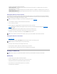
Key Functions — This field appears below the Option Field and lists keys and their functions within the active system setup field. System Setup Options NOTE: Depending on your computer and installed devices, the items listed in this section may or may not appear. System System Info Lists the computer name, BIOS version, and service tag. CPU Info Identifies whether the computer's processor supports Hyper-Threading and identifies the CPU speed, bus speed, clock speed, and L2 cache.
l l l l AT — The port is configured for IBM® AT compatibility. PS/2 — The port is configured for IBM PS/2 compatibility. EPP — The port is set for enhanced parallel port protocol. ECP — The port is set for extended capability port protocol. LPT Port Address This option sets the address that the built-in parallel port uses. The settings are 378h (default setting), 278h, and 3BCh. PCI Slots Enables or disables the PCI slots.
If the option is Disabled, the system password is disabled by a jumper setting on the system board. To disable the system password, enter the password at the prompt and hit . Drive Password Set this password to prevent unauthorized users from accessing the hard drive. NOTE: The option appears for each installed hard drive that supports hard-drive passwords. If no drives support a drive password, this option will not display.
is in the drive, the computer generates an error message. l Onboard SATA Hard Drive — The computer attempts to boot from the primary serial ATA hard drive. If no operating system is on the drive, the computer generates an error message. l Onboard IDE Hard Drive — The computer attempts to boot from the primary IDE hard drive, if applicable. If no operating system is on the drive, the computer generates an error message. l Onboard or USB CD-ROM Drive — The computer attempts to boot from the CD drive.
Floppy Drive 1. In system setup, set the Diskette Drive option to USB. 2. Save and exit system setup. 3. Connect the USB floppy drive, insert a bootable floppy, and re-boot the system. Clearing Forgotten Passwords CAUTION: Before you begin any of the procedures in this section, follow the safety instructions located in the Product Information Guide. NOTICE: This process erases both the system and administrator passwords. 1. Follow the procedures in "Before You Begin." 2.
jumpered unjumpered 3. Replace the computer cover. 4. Connect your computer and monitor to electrical outlets, and turn them on. 5. After the Microsoft® Windows® desktop appears on your computer, shut down your computer. 6. Turn off the monitor and disconnect it from the electrical outlet. 7. Disconnect the computer power cable from the electrical outlet, and press the power button to ground the system board. 8. Open the computer cover. 9.
2. Click Hardware and click Device Manager. 3. In the Device Manager window, click the plus (+) sign next to the processor type. If Hyper- Threading is enabled, the processor is listed twice. You can enable or disable Hyper-Threading through system setup. Power Management Your computer can be set to use less power when you are not working. You control the power usage through the operating system installed on your computer and certain option settings in system setup.
Back to Contents Page Battery Dell™ OptiPlex™ 210L User's Guide Replacing the Battery Replacing the Battery CAUTION: Before you begin any of the procedures in this section, follow the safety instructions in the Product Information Guide. NOTICE: To prevent static damage to components inside your computer, discharge static electricity from your body before you touch any of your computer's electronic components. You can do so by touching an unpainted metal surface on the computer chassis.
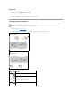
1 system battery 2 positive side of battery connector 3 battery socket tab 4 battery socket NOTICE: To avoid damage to the battery connector, you must firmly support the connector while replacing the battery. 5. Install the new system battery. a. Support the battery connector by pressing down firmly on the positive side of the connector. b. Hold the battery with the "+" facing up, and slide it under the securing tabs at the positive side of the connector. c.
Back to Contents Page Before You Begin Dell™ OptiPlex™ 210L User's Guide Recommended Tools Turning Off Your Computer Before Working Inside Your Computer This chapter provides procedures for removing and installing the components in your computer. Unless otherwise noted, each procedure assumes that the following conditions exist: l You have performed the steps in "Turning Off Your Computer" and "Before Working Inside Your Computer.
4. If applicable, remove the computer stand (for instructions, see the documentation that came with the stand) and the cable cover, if attached. CAUTION: To guard against electrical shock, always unplug your computer from the electrical outlet before removing the cover. 5. Remove the computer cover: l Remove the mini tower computer cover. l Remove the small desktop computer cover.
Back to Contents Page Cleaning Your Computer Dell™ OptiPlex™ 210L User's Guide CAUTION: Before you begin any of the procedures in this section, follow the safety instructions located in the Product Information Guide. Computer, Keyboard, and Monitor CAUTION: Before you clean your computer, disconnect the computer from the electrical outlet. Clean your computer with a soft cloth dampened with water. Do not use liquid or aerosol cleaners, which may contain flammable substances.
some protection from dust, fingerprints, and scratches. Cleaning products for CDs are safe to use on DVDs.
Back to Contents Page Replacing the Computer Cover Dell™ OptiPlex™ 210L User's Guide CAUTION: Before you begin any of the procedures in this section, follow the safety instructions in the Product Information Guide. 1. Ensure that all cables are connected, and fold cables out of the way. Gently pull the power cables toward you so that they do not get caught underneath the drives. 2. Ensure that no tools or extra parts are left inside the computer. 3. To replace the cover: a.
Back to Contents Page Finding Information Dell™ OptiPlex™ 210L User's Guide NOTE: Some features may not be available for your computer or in certain countries. NOTE: Additional information may ship with your computer.
1. 2. Click the Start button and click Help and Support. Click User's and system guides and click User's guides. The User's Guide is also available on the optional Drivers and Utilities CD (Resource CD). l l Service Tag and Express Service Code Microsoft Windows License Label Service Tag and Microsoft Windows License These labels are located on your computer.
Back to Contents Page Getting Help Dell™ OptiPlex™ 210L User's Guide Technical Assistance Problems With Your Order Product Information Returning Items for Warranty Repair or Credit Before You Call Contacting Dell Technical Assistance If you need help with a technical problem, Dell is ready to assist you. CAUTION: If you need to remove the computer covers, first disconnect the computer power and modem cables from all electrical outlets. 1. Complete the procedures in "Solving Problems.
apsupport@dell.com (Asian/Pacific countries only) support.jp.dell.com (Japan only) support.euro.dell.com (Europe only) l Electronic Quote Service sales@dell.com apmarketing@dell.com (Asian/Pacific countries only) sales_canada@dell.com (Canada only) l Electronic Information Service info@dell.com AutoTech Service Dell's automated technical support service—AutoTech—provides recorded answers to the questions most frequently asked by Dell customers about their portable and desktop computers.
5. Pack the equipment to be returned in the original (or equivalent) packing materials. You are responsible for paying shipping expenses. You are also responsible for insuring any product returned, and you assume the risk of loss during shipment to Dell. Collect On Delivery (C.O.D.) packages are not accepted. Returns that are missing any of the preceding requirements will be refused at Dell's receiving dock and returned to you. Before You Call NOTE: Have your Express Service Code ready when you call.
E-mail: us_latin_services@dell.com Argentina (Buenos Aires) E-mail for desktop and portable computers: la-techsupport@dell.com International Access Code: 00 E-mail for servers and EMC® storage products: la_enterprise@dell.com Country Code: 54 City Code: 11 toll-free: 0-800-444-0730 Tech Support toll-free: 0-800-444-0733 Tech Support Services toll-free: 0-800-444-0724 Sales Aruba General Support E-mail (Australia): au_tech_support@dell.com E-mail (New Zealand): nz_tech_support@dell.
Technical Support (med./large bus., government) toll-free: 1-800-387-5757 International Access Code: 011 Technical Support (printers, projectors, televisions, handhelds, digital jukebox, and wireless) Cayman Islands 1-877-335-5767 Sales (Home Sales/Small Business) toll-free: 1-800-387-5752 Sales (med./large bus.
E-mail: support.euro.dell.com/fi/fi/emaildell/ International Access Code: 990 Technical Support Country Code: 358 City Code: 9 Customer Care 09 253 313 38 Fax 09 253 313 99 Switchboard 09 253 313 00 Website: support.euro.dell.com E-mail: support.euro.dell.
Technical Support for Inspiron XPS computers only Technical Support for all other Dell computers Ireland (Cherrywood) U.K. Technical Support (dial within U.K. only) Home User Customer Care International Access Code: 16 Small Business Customer Care Country Code: 353 U.K. Customer Care (dial within U.K. only) Corporate Customer Care City Code: 1 Corporate Customer Care (dial within U.K. only) Ireland Sales U.K. Sales (dial within U.K.
Luxembourg Technical Support (Brussels, Belgium) Home/Small Business Sales (Brussels, Belgium) 3420808075 toll-free: 080016884 International Access Code: 00 Country Code: 352 Corporate Sales (Brussels, Belgium) 02 481 91 00 Customer Care (Brussels, Belgium) 02 481 91 19 Fax (Brussels, Belgium) 02 481 92 99 Switchboard (Brussels, Belgium) Macao Country Code: 853 Technical Support Customer Service (Xiamen, China) 34 160 910 Transaction Sales (Xiamen, China) 29 693 115 Website: support.ap.dell.
Poland (Warsaw) E-mail: pl_support_tech@dell.com Customer Service Phone International Access Code: 011 Customer Care Country Code: 48 City Code: 22 Portugal International Access Code: 00 57 95 700 57 95 999 Sales 57 95 999 Customer Service Fax 57 95 806 Reception Desk Fax 57 95 998 Switchboard 57 95 999 Website: support.euro.dell.com E-mail: support.euro.dell.
Country Code: 46 Home/Small Business Customer Care Employee Purchase Program (EPP) Support City Code: 8 08 587 70 527 20 140 14 44 Technical Support Fax 08 590 05 594 Sales 08 590 05 185 Website: support.euro.dell.com E-mail: Tech_support_central_Europe@dell.com Switzerland (Geneva) E-mail for French-speaking HSB and Corporate Customers: support.euro.dell.
International Access Code: 011 Employee Purchase Program (EPP) Customers Country Code: 1 Printers and Projectors Technical Support toll-free: 1-800-695-8133 toll-free: 1-877-459-7298 Public (government, education, and healthcare) Customer Service and Technical Support toll-free: 1-800-456-3355 Employee Purchase Program (EPP) Customers toll-free: 1-800-234-1490 toll-free: 1-800-289-3355 Dell Sales or toll-free: 1-800-879-3355 Dell Outlet Store (Dell refurbished computers) toll-free: 1-888-798-7561
Back to Contents Page Glossary Dell™ OptiPlex™ 210L User's Guide Terms in this Glossary are provided for informational purposes only and may or may not describe features included with your particular computer. A AC — alternating current — The form of electricity that powers your computer when you plug the AC adapter power cable in to an electrical outlet.
bootable disk — A disk that you can use to start your computer. In case your hard drive is damaged or your computer has a virus, ensure that you always have a bootable CD or floppy disk available. bps — bits per second — The standard unit for measuring data transmission speed. BTU — British thermal unit — A measurement of heat output. bus — A communication pathway between the components in your computer. bus speed — The speed, given in MHz, that indicates how fast a bus can transfer information.
Control Panel — A Windows utility that allows you to modify operating system and hardware settings, such as display settings. controller — A chip that controls the transfer of data between the processor and memory or between the processor and devices. CRIMM — continuity rambus in-line memory module — A special module that has no memory chips and is used to fill unused RIMM slots. cursor — The marker on a display or screen that shows where the next keyboard, touch pad, or mouse action will occur.
DVD drive — A drive that uses optical technology to read data from DVDs and CDs. DVD player — The software used to watch DVD movies. The DVD player displays a window with buttons that you use to watch a movie. DVD+RW — DVD rewritable — A rewritable version of a DVD. Data can be written to a DVD+RW disc, and then erased and written over (rewritten). (DVD+RW technology is different from DVD-RW technology.
FCC — Federal Communications Commission — A U.S. agency responsible for enforcing communications-related regulations that state how much radiation computers and other electronic equipment can emit. floppy drive — A disk drive that can read and write to floppy disks. folder — A term used to describe space on a disk or drive where files are organized and grouped. Files in a folder can be viewed and ordered in various ways, such as alphabetically, by date, and by size.
Hz — hertz — A unit of frequency measurement that equals 1 cycle per second. Computers and electronic devices are often measured in kilohertz (kHz), megahertz (MHz), gigahertz (GHz), or terahertz (THz). I IC — Industry Canada — The Canadian regulatory body responsible for regulating emissions from electronic equipment, much as the FCC does in the United States.
LCD — liquid crystal display — The technology used by portable computer and flat-panel displays. LED — light-emitting diode — An electronic component that emits light to indicate the status of the computer. local bus — A data bus that provides a fast throughput for devices to the processor. LPT — line print terminal — The designation for a parallel connection to a printer or other parallel device. M Mb — megabit — (written as Mb) A measurement of memory chip capacity that equals 1024 Kb.
N network adapter — A chip that provides network capabilities. A computer may include a network adapter on its system board, or it may contain a PC Card with an adapter on it. A network adapter is also referred to as a NIC (network interface controller). NIC — See network adapter. notification area — The section of the Windows taskbar that contains icons for providing quick access to programs and computer functions, such as the clock, volume control, and print status. Also referred to as system tray.
processor — A computer chip that interprets and executes program instructions. Sometimes the processor is referred to as the CPU (central processing unit). program — Any software that processes data for you, including spreadsheet, word processor, database, and game packages. Programs require an operating system to run. PS/2 — personal system/2 — A type of connector for attaching a PS/2-compatible keyboard, mouse, or keypad.
stopped responding. SDRAM — synchronous dynamic random-access memory — A type of DRAM that is synchronized with the optimal clock speed of the processor. serial connector — An I/O port often used to connect devices such as a handheld digital device or digital camera to your computer. Service Tag — A bar code label on your computer that identifies your computer when you access Dell Support at support.dell.com or when you call Dell for customer service or technical support.
system tray — See notification area. T TAPI — telephony application programming interface — Enables Windows programs to operate with a wide variety of telephony devices, including voice, data, fax, and video. text editor — A program used to create and edit files that contain only text; for example, Windows Notepad uses a text editor. Text editors do not usually provide word wrap or formatting functionality (the option to underline, change fonts, and so on).
W W — watt — The measurement of electrical power. One W is 1 ampere of current flowing at 1 volt. WHr — watt-hour — A unit of measure commonly used to indicate the approximate capacity of a battery. For example, a 66-WHr battery can supply 66 W of power for 1 hour or 33 W for 2 hours. wallpaper — The background pattern or picture on the Windows desktop. Change your wallpaper through the Windows Control Panel. You can also scan in your favorite picture and make it wallpaper.
Back to Contents Page Memory Dell™ OptiPlex™ 210L User's Guide DDR2 Memory Overview Addressing Memory With 4-GB Configurations Removing Memory Replacing/Adding Additional Memory For information on the type of memory supported by your computer, see the "Memory" section of the specifications for your computer: l Mini Tower Computer Specifications l Desktop Computer Specifications NOTICE: Before you install new memory modules, download the most recent BIOS for your computer from the Dell Suppor
Removing Memory CAUTION: Before you begin any of the procedures in this section, follow the safety instructions in the Product Information Guide. NOTICE: If you remove your original memory modules from the computer during a memory upgrade, keep them separate from any new modules that you may have, even if you purchased the new modules from Dell. If possible, do not pair an original memory module with a new memory module. Otherwise, your computer may not start properly.
3. Align the notch on the bottom of the module with the crossbar in the connector. 1 cutouts (2) 2 memory module 3 notch 4 crossbar NOTICE: To avoid damage to the memory module, press the module straight down into the connector while you apply equal force to each end of the module. 4. Insert the module into the connector until the module snaps into position. If you insert the module correctly, the securing clips snap into the cutouts at each end of the module. 5. Replace the computer cover. 6.
Back to Contents Page Mini Tower Computer Dell™ OptiPlex™ 210L User's Guide About Your Mini Tower Computer Inside Your Computer About Your Mini Tower Computer Front View 1 CD/DVD drive Insert a CD or DVD (if applicable) into this drive. 2 floppy drive Insert a floppy disk into this drive. 3 hard-drive activity light This light flickers when the hard drive is in use. 4 USB 2.
To exit from a power-saving mode, press the power button or use the keyboard or the mouse if it is configured as a wake device in the Windows Device Manager. For more information about sleep modes and exiting from a power-saving mode, see "Power Management." See "System Lights" for a description of light codes that can help you troubleshoot problems with your computer. 8 headphone connector Use the headphone connector to attach headphones and most kinds of speakers.
1 parallel connector Connect a parallel device, such as a printer, to the parallel connector. If you have a USB printer, plug it into a USB connector. NOTE: The integrated parallel connector is automatically disabled if the computer detects an installed card containing a parallel connector configured to the same address. For more information, see "System Setup Options.
1 CD/DVD drive 5 system board 2 floppy drive 6 heat sink assembly 3 power supply 7 hard drive 4 chassis manual voltage-selection switch System Board Components 1 fan connector (FAN) 9 2 processor connector (CPU) 10 PCI card connector (2) PCI Express x1 card connector 3 power connector (12VPOWER) 11 FlexBay USB connector 4 memory module connectors (DIMM_1, DIMM_2) 12 piezo buzzer 5 serial ATA drive connectors (SATA0, SATA2) 13 password jumper (PSWD) 6 front-panel connector (FNT_P
Jumper Settings Mini Tower Computer Jumper Setting Description PSWD Password features are enabled (default). Password features are disabled. RTCRST The real-time clock has not been reset. The real-time clock is being reset (jumpered temporarily).
Back to Contents Page Dell™ OptiPlex™ 210L User's Guide PCI and PCI Express Cards PCI and PCI Express Cards CAUTION: Before you begin any of the procedures in this section, follow the safety instructions located in the Product Information Guide. NOTICE: To prevent static damage to components inside your computer, discharge static electricity from your body before you touch any of your computer's electronic components. You can do so by touching an unpainted metal surface on the computer chassis.
4. Set the card retention mechanism aside in your work area. 5. If you are installing a new card, remove the filler bracket to create a card-slot opening. Then continue with step 5. 6. If you are replacing a card that is already installed in the computer, remove the card. If necessary, disconnect any cables connected to the card. 7. Prepare the new card for installation.
16. a. Enter system setup, select Network Controller, and change the setting to Off. b. Connect the network cable to the network adapter card's connectors. Do not connect the network cable to the integrated network connector on the back panel of the computer. Install any drivers required for the card as described in the card documentation. Removing a PCI Card 1. Follow the procedures in "Before You Begin." 2.
1 card fully seated 2 card not fully seated 3 bracket within slot 4 bracket caught outside of slot 8. Gently press down on the card retention mechanism to secure the adapter bracket in place. 9. Close the card retention latch by snapping it into place. NOTICE: To connect a network cable, first plug the cable into the network wall jack and then plug it into the computer. 10. Replace the computer cover. 11. Uninstall the card's driver.
1 card retention latch 4 card-edge connector 2 alignment guide 5 card connector 3 card 6 release tab 2. Gently push the release tab on the card retention latch from the inside to pivot the latch open. The latch will remain in the open position. 3. Open the card retention mechanism that secures the card in place from the top: a. Place your thumb on the top of the card retention mechanism and grip the bottom of the retention mechanism with your fingers. b.
1 card fully seated 2 card not fully seated 3 bracket within slot 4 bracket caught outside of slot 9. Before you replace and lower the card retention mechanism, ensure that: l The tops of all cards and filler brackets are flush with the alignment bar. l The notch in the top of the card or filler bracket fits around the alignment guide. 10. Gently press down on the card retention mechanism to secure the adapter bracket in place. 11.
1 card retention latch 4 card-edge connector 2 alignment guide 5 card connector 3 card 6 release tab 2. 3. 4. Gently push the release tab on the card retention latch from the inside to pivot the latch open. Because the latch is captive, it will remain in the open position. Open the card retention mechanism that secures the card in place from the top: a. Place your thumb on the top of the card retention mechanism and grip the bottom of the retention mechanism with your fingers. b.
Back to Contents Page Dell™ OptiPlex™ 210L User's Guide Removing the Computer Cover Removing the Computer Cover CAUTION: Before you begin any of the procedures in this section, follow the safety instructions located in the Product Information Guide. CAUTION: To guard against electrical shock, always unplug your computer from the electrical outlet before removing the computer cover. 1. Follow the procedures in "Before You Begin." 2. Lay the computer on its side. 3.
Back to Contents Page Dell™ OptiPlex™ 210L User's Guide Drives Drives Your computer supports: l Two serial ATA hard drives l Two floppy or optional Zip drives l Two CD or DVD drives NOTE: Due to the limited number of drive bays and IDE controllers on this computer, you will not be able to connect all supported devices at once. 1 CD/DVD drive 2 floppy drive 3 hard drive General Installation Guidelines Connect CD/DVD drives to the connector labeled "IDE" on the system board.
1 colored stripe on IDE cable 2 interface cable connector 3 interface connector Most interface connectors are keyed for correct insertion; that is, a notch or a missing pin on one connector matches a tab or a filled-in hole on the other connector. Keyed connectors ensure that the pin-1 wire in the cable (indicated by the colored stripe along one edge of the IDE cable—serial ATA cables do not use a colored stripe) goes to the pin-1 end of the connector.
CAUTION: To guard against electrical shock, always unplug your computer from the electrical outlet before removing the computer cover. NOTICE: To avoid damage to the drive, do not set it on a hard surface. Instead, set the drive on a surface, such as a foam pad, that will sufficiently cushion it. Removing a Hard Drive 1. If you are replacing a hard drive that contains data you want to keep, back up your files before you begin this procedure. 2.
1. Unpack the replacement hard drive, and prepare it for installation. 2. Check the documentation for the drive to verify that it is configured for your computer. NOTE: If your replacement hard drive does not have the plastic hard-drive bracket attached, remove the bracket from the existing drive by unsnapping it from the drive. Snap the bracket onto the new drive. 1 hard drive 2 hard-drive bracket 1 hard drive 2 hard-drive bracket 3.
7. 8. 9. Replace the computer cover. If the drive you just installed is the primary drive, insert a bootable medium into your boot drive. See the documentation that came with the drive for instructions on installing any software required for drive operation. Enter system setup and update the appropriate Primary Drive option (0 or 1). 10. Exit system setup, and reboot the computer. 11. Partition and logically format your drive before you proceed to the next step.
8. Attach the serial ATA connector removed in step 5 to the first hard drive. 9. Locate an unused serial ATA connector on the system board and attach a drive cable to this connector and to the second hard drive. 1 hard-drive cable 2 hard-drive cable on system board 3 power cable 10. Replace the computer cover. Drive-Panel Inserts If you are installing a new floppy or CD/DVD drive instead of replacing a drive, remove the drive-panel inserts. 1. Follow the procedures in "Before You Begin.
1 drive panel 2 release tab 3 drive-panel insert 3. Select the drive-panel insert in front of the drive bay that you want to use. 4. Gently press the release tab of the insert to remove it from the drive panel. 1 CD/DVD-drive panel insert 2 floppy-drive panel insert 3 holder for shoulder screws 5. Reattach the drive panel to the front of the computer. The drive panel only fits one way.
Floppy Drive CAUTION: Before you begin any of the procedures in this section, follow the safety instructions located in the Product Information Guide. CAUTION: To guard against electrical shock, always unplug your computer from the electrical outlet before removing the computer cover. Removing the Floppy Drive 1. Follow the procedures in "Before You Begin." 2. Remove the drive panel by sliding the drive release latch downward to open the panel, and then remove it from the hinges. 3.
2. 3. If you are installing a new floppy drive, remove the drive-panel insert for your new drive, remove the shoulder screws from the inside of the drive-panel insert and attach the screws to the new drive. Align the shoulder screws on the floppy drive with the shoulder screw slots, and gently slide the drive into the bay until it clicks into place. 1 floppy drive 2 shoulder screws (4) 3 shoulder screw slots (2) 4. Attach the power and floppy-drive cables to the floppy drive.
7. Verify that your computer works correctly by running the Dell Diagnostics. CD/DVD Drive CAUTION: Before you begin any of the procedures in this section, follow the safety instructions located in the Product Information Guide. CAUTION: To guard against electrical shock, always unplug your computer from the electrical outlet before replacing the cover. Removing a CD/DVD Drive 1. Follow the procedures in "Before You Begin." 2.
1 CD/DVD drive 2 shoulder screws (3) 3 shoulder screw slots (2) 6. Connect the power and CD/DVD drive cables to the drive and to the system board. NOTE: The CD/DVD drive cable may be a SATA cable and appear differently than the image below. For information on SATA cable connectors, see "General Installation Guidelines." 1 power cable 2 CD/DVD drive cable 3 CD/DVD drive connector (IDE) 7.
Dell™ OptiPlex™ 210L User's Guide Mini Tower Computer Finding Information Before You Begin Recommended Tools Turning Off Your Computer Before Working Inside Your Computer Mini Tower Computer About Your Mini Tower Computer Inside Your Computer Mini Tower Computer Specifications Removing the Computer Cover I/O Panel Drives PCI and PCI Express Cards Power Supply Processor Advanced Features LegacySelect Technology Control Manageability Security Password Protection System Setup Booting to a USB Device Cle
For a complete list of abbreviations and acronyms, see the Glossary. If you purchased a Dell™ n Series computer, any references in this document to Microsoft® Windows® operating systems are not applicable. Information in this document is subject to change without notice. © 2006 Dell Inc. All rights reserved. Reproduction in any manner whatsoever without the written permission of Dell Inc. is strictly forbidden.
Back to Contents Page Dell™ OptiPlex™ 210L User's Guide I/O Panel I/O Panel Removing the I/O Panel CAUTION: Before you begin any of the procedures in this section, follow the safety instructions located in the Product Information Guide. CAUTION: To guard against electrical shock, always unplug your computer from the electrical outlet before removing the cover. NOTE: Note the routing of all cables as you remove them so that you can re-route them correctly when installing the new I/O panel. 1.
Back to Contents Page
Back to Contents Page Dell™ OptiPlex™ 210L User's Guide Processor Processor CAUTION: Before you begin any of the procedures in this section, follow the safety instructions located in the Product Information Guide. NOTICE: To prevent static damage to components inside your computer, discharge static electricity from your body before you touch any of your computer's electronic components. You can do so by touching an unpainted metal surface on the computer chassis. Removing the Processor 1.
1 center cover latch 2 processor cover 3 processor 4 socket 5 release lever NOTICE: When replacing the processor, do not touch any of the pins inside the socket or allow any objects to fall on the pins in the socket. 5. Gently remove the processor from the socket. Leave the release lever extended in the release position so that the socket is ready for the new processor. Installing the Processor NOTICE: Ground yourself by touching an unpainted metal surface on the back of the computer.
1 processor cover 6 release lever 2 tab 7 front alignment-notch 3 processor 8 socket and processor pin-1 indicator 4 processor socket 9 rear alignment-notch 5 center cover latch NOTICE: To avoid damage, ensure that the processor aligns properly with the socket, and do not use excessive force when you install the processor. 6. Set the processor lightly in the socket and ensure that the processor is positioned correctly. 7.
Back to Contents Page Dell™ OptiPlex™ 210L User's Guide Power Supply Power Supply Replacing the Power Supply CAUTION: Before you begin any of the procedures in this section, follow the safety instructions located in the Product Information Guide. NOTICE: To prevent static damage to components inside your computer, discharge static electricity from your body before you touch any of your computer's electronic components. You can do so by touching an unpainted metal surface on the computer chassis.
9. Reconnect the DC power cables to the power supply. 10. Connect the AC power cable to the AC power connector. 11. Replace the computer cover. DC Power Connectors DC Power Connector P1 Pin Number Signal name 18-AWG Wire 1 +3.3 VDC Orange 2 +3.3 VDC Orange 3 GND Black 4 VCC (+5 V) Red 5 GND Black 6 VCC (+5 V) Red 7 GND Black 8 PS_PWRGOOD Gray 9 P5AUX Purple 10 V_12P0_DIG Yellow 11 V_12P0_DIG Yellow 12 +3.3 V Orange 13 +3.
19 GND Black 20 NC N/C 21 VCC (+5 V) Red 22 VCC (+5 V) Red 23 VCC (+5 V) Red 24 GND Black *Use 22-AWG wire instead of 18-AWG wire. DC Power Connector P2 Pin Number Signal Name 18-AWG Wire 1 COM Black 2 COM Black 3 +12 VDC Yellow 4 +12 VDC Yellow DC Power Connectors P3 and P5 Pin Number Signal name 18-AWG Wire 1 +3.
Pin Number Signal Name 22-AWG Wire 1 +5 VCD Red 2 COM Black 3 COM Black 4 +12 VDC Yellow DC Power Connectors P8 and P9 Pin Number Signal name 18-AWG Wire 1 +12 VDC Yellow 2 COM Black 3 COM Black 4 +5 VDC Red Back to Contents Page
Back to Contents Page Dell™ OptiPlex™ 210L User's Guide Mini Tower Computer Specifications Mini Tower Computer Specifications Microprocessor Microprocessor type Intel® Pentium® or Celeron® processor Level 1 (L1) cache 32 KB Level 2 (L2) cache 512-KB, 1-MB, or 2-MB pipelined-burst, eight-way set associative, write-back SRAM Memory Type 400-MHz and 533-MHz DDR2 SDRAM Memory connectors 2 Memory modules supported 256-MB, 512-MB, 1-GB or 2-GB non-ECC Minimum memory dual-channel: 512 MB sing
Expansion Bus Bus type PCI 2.3 SATA 1.0a USB 2.0 PCI Express 1.0a Bus speed PCI: 33 MHz SATA: 1.5 Gbps and 3.0 Gbps USB: 480 Mbps PCI Express x1: 5 Gbps Cards: full-height cards supported PCI: connectors two connector size 120 pins connector data width 32 bits (maximum) PCI Express: connectors one x1 power 10 W maximum connector size 36 pins connector data width (maximum) one PCI Express lane Drives Externally accessible one 3.5-inch drive two 5.
Controls and Lights Power control push button Power light green light — Blinking green indicates sleep mode; solid green indicates power-on state. amber light — Blinking amber indicates a problem with an installed device; solid amber indicates an internal power problem (see "Power Problems").
Back to Contents Page FCC Notices (U.S. Only) Dell™ OptiPlex™ 210L User's Guide Electromagnetic Interference (EMI) is any signal or emission, radiated in free space or conducted along power or signal leads, that endangers the functioning of a radio navigation or other safety service or seriously degrades, obstructs, or repeatedly interrupts a licensed radio communications service.
l Increase the separation between the equipment and the receiver. l Connect the equipment into an outlet on a circuit different from that to which the receiver is connected. l Consult the dealer or an experienced radio/television technician for help. FCC Identification Information The following information is provided on the device or devices covered in this document in compliance with FCC regulations: l Model numbers: DCTR and DCNE l Company name: Dell Inc.
Back to Contents Page Reinstalling Drivers and the Operating System Dell™ OptiPlex™ 210L User's Guide Drivers Using Microsoft® Windows® XP System Restore Reinstalling Microsoft Windows XP CAUTION: Before you begin any of the procedures in this section, follow the safety instructions in the Product Information Guide. NOTICE: You must use Microsoft® Windows® XP Service Pack 1 or later when you reinstall the Microsoft Windows XP operating system.
1. Click the Start button and click Control Panel. 2. Under Pick a Category, click Performance and Maintenance. 3. Click System. 4. In the System Properties window, click the Hardware tab. 5. Click Device Manager. 6. Right-click the device for which the new driver was installed and click Properties. 7. Click the Drivers tab. 8. Click Roll Back Driver.
Restoring the Computer to an Earlier Operating State NOTICE: Before you restore the computer to an earlier operating state, save and close any open files and exit any open programs. Do not alter, open, or delete any files or programs until the system restoration is complete. 1. Click the Start button, point to All Programs® Accessories® System Tools, and then click System Restore. 2. Ensure that Restore my computer to an earlier time is selected and click Next. 3.
If you are considering reinstalling the Windows XP operating system to correct a problem with a newly installed driver, first try using Windows XP Device Driver Rollback. If Device Driver Rollback does not resolve the problem, then use System Restore to return your operating system to the operating state it was in before you installed the new device driver. NOTICE: Before performing the installation, back up all data files on your primary hard drive.
9. If the Modem Dialing Information screen appears, enter the requested information and click Next. 10. Enter the date, time, and time zone in the Date and Time Settings window, and click Next. 11. If the Networking Settings screen appears, click Typical and click Next. 12. If you are reinstalling Windows XP Professional and you are prompted to provide further information regarding your network configuration, enter your selections.
Back to Contents Page Replacing the System Board Dell™ OptiPlex™ 210L User's Guide Removing the System Board 1. 2. Shut down the computer through the Start menu. Ensure that your computer and attached devices are turned off. If your computer and attached devices did not automatically turn off when you shut down your computer, turn them off now. NOTICE: To disconnect a network cable, first unplug the cable from your computer and then unplug it from the network wall jack. 3.
1 mini tower system board 2 screws (10) Small Desktop System Board Screws 1 desktop system board 2 screws (10) Place the system board assembly that you just removed next to the replacement system board to ensure it is identical. Replacing the System Board 1. Gently align the board into the chassis and slide it toward the back of the computer. 2. Replace the screws on the system board. 3. Replace any components and cables that you removed from the system board. 4.
Back to Contents Page Desktop Computer Dell™ OptiPlex™ 210L User's Guide About Your Desktop Computer Inside Your Computer About Your Desktop Computer Front View 1 USB 2.0 connectors (2) Use the USB connectors on the front of the computer for devices that you connect occasionally, such as joysticks or cameras, or for bootable USB devices (see "System Setup" for more information about booting to a USB device).
Back View 1 card slots Access connectors for any installed PC Cards. 2 back-panel connectors Plug serial, USB, and other devices into the appropriate connector. 3 power connector Insert the power cable into this connector. 4 voltage selection switch Your computer is equipped with a manual voltage-selection switch. To help avoid damaging a computer with a manual voltage-selection switch, set the switch for the voltage that most closely matches the AC power available in your location.
It is recommended that you use Category 5 wiring and connectors for your network. If you must use Category 3 wiring, force the network speed to 10 Mbps to ensure reliable operation. 4 network activity light This light flashes yellow when the computer is transmitting or receiving network data. A high volume of network traffic may make this light appear to be in a steady "on" state.
1 fan connector (FAN) 9 2 processor connector (CPU) 10 PCI card connector (2) PCI Express x1 card connector 3 power connector (12VPOWER) 11 FlexBay USB connector 4 memory module connectors (DIMM_1, DIMM_2) 12 piezo buzzer 5 serial ATA drive connectors (SATA0, SATA2) 13 password jumper (PSWD) NOTE: The SATA2 connector is not supported with this system.
Password features are disabled. RTCRST The real-time clock has not been reset. The real-time clock is being reset (jumpered temporarily).
Back to Contents Page Dell™ OptiPlex™ 210L User's Guide PCI and PCI Express Cards PCI and PCI Express Cards CAUTION: Before you begin any of the procedures in this section, follow the safety instructions in the Product Information Guide. NOTICE: To prevent static damage to components inside your computer, discharge static electricity from your body before you touch any of your computer's electronic components. You can do so by touching an unpainted metal surface on the computer chassis.
CAUTION: Some network adapters automatically start the computer when they are connected to a network. To guard against electrical shock, be sure to unplug your computer from its electrical outlet before installing any cards. 6. Place the card in the connector and press down firmly. Ensure that the card is fully seated in the slot. 1 card fully seated 2 card not fully seated 3 bracket within slot 4 bracket caught outside of slot 7. Gently press down on the card retention latch to secure the card.
1 release tab 4 card-edge connector 2 card retention latch 5 card connector 3 card 5. If you are removing the card permanently, install a filler bracket in the empty card-slot opening. If you need a filler bracket, contact Dell. NOTE: Installing filler brackets over empty card-slot openings is necessary to maintain FCC certification of the computer. The brackets also keep dust and dirt out of your computer. 6. Snap the card retention latch into place.
Back to Contents Page Dell™ OptiPlex™ 210L User's Guide Removing the Computer Cover Removing the Computer Cover CAUTION: Before you begin any of the procedures in this section, follow the safety instructions in the Product Information Guide. CAUTION: To guard against electrical shock, always unplug your computer from the electrical outlet before removing the computer cover. 1. Follow the procedures in "Before You Begin." 2.
Back to Contents Page Dell™ OptiPlex™ 210L User's Guide Drives Drives Your computer supports: l One serial ATA hard drive l One optional ATA hard drive l One optional floppy drive l One optional CD or DVD drive 1 CD/DVD drive 2 floppy drive 3 hard drive General Installation Guidelines Connect CD/DVD drives to the connector labeled "IDE" on the system board. Serial ATA hard drives should be connected to the connectors labeled "SATA0" or "SATA2" on the system board.
Most interface connectors are keyed for correct insertion; that is, a notch or a missing pin on one connector matches a tab or a filled-in hole on the other connector. Keyed connectors ensure that the pin-1 wire in the cable (indicated by the colored stripe along one edge of the IDE cable—serial ATA cables do not use a colored stripe) goes to the pin-1 end of the connector. The pin-1 end of a connector on a board or a card is usually indicated by a silk-screened "1" printed directly on the board or card.
1 drive release latch 2 CD/DVD drive 3. Disconnect the power and CD/DVD drive cables from the back of the drive. Installing a CD/DVD Drive 1. Unpack the drive and prepare it for installation. Check the documentation that accompanied the drive to verify that the drive is configured for your computer. If you are installing an IDE drive, configure the drive for the cable select setting. 2. 3. If you are installing a new drive: a.
6. Check all cable connections, and fold cables out of the way to provide airflow for the fan and cooling vents. 7. Replace the computer cover. 8. Update your configuration information by setting the appropriate Drive option (0 or 1) under Drives. See "System Setup" for more information. 9. Verify that your computer works correctly by running the Dell Diagnostics.
1 drive release latch 2 floppy drive 4. Disconnect the power and floppy-drive cables from the back of the floppy drive. Installing a Floppy Drive 1. 2. If you are installing a new drive: a. Use a small flat-edge screw driver on the back side of the drive-panel insert to gently pop off the insert. b. Remove the four shoulder screws from the drive-panel insert. If you are replacing an existing drive: Remove the four shoulder screws from the existing drive. 3.
2 slot verification number 6. Replace the CD/DVD drive. 7. Check all cable connections, and fold cables out of the way to provide airflow for the fan and cooling vents. 8. Replace the computer cover. 9. Enter system setup and set the Diskette Drive option to enable your new floppy drive. 10. Verify that your computer works correctly by running the Dell Diagnostics.
Installing a Hard Drive 1. Check the documentation for the drive to verify that it is configured for your computer. NOTICE: To avoid damage to the drive, do not set it on a hard surface. Instead, set the drive on a surface, such as a foam pad, that will sufficiently cushion it. 2. 3. Unpack the replacement hard drive, and prepare it for installation.
1 hard drive 2 slot verification number 7. Replace the floppy drive and CD/DVD drive. 8. Check all connectors to be certain that they are properly cabled and firmly seated. 9. Replace the computer cover. 10. If the drive you just installed is the primary drive, insert a bootable medium into your boot drive. 11. Turn on the computer. 12. Enter system setup and update the appropriate Primary Drive option (0 or 2). 13. Exit system setup, and reboot the computer. 14.
Dell™ OptiPlex™ 210L User's Guide Desktop Computer Finding Information Before You Begin Recommended Tools Turning Off Your Computer Before Working Inside Your Computer Desktop Computer About Your Desktop Computer Inside Your Computer Desktop Computer Specifications Removing the Computer Cover I/O Panel Drives PCI and PCI Express Cards Power Supply Processor Advanced Features LegacySelect Technology Control Manageability Security Password Protection System Setup Booting to a USB Device Clearing Forgott
Microsoft Corporation; IBM is a registered trademark of International Business Machines Corporation; Bluetooth is a trademark owned by Bluetooth SIG, Inc. and is used by Dell Inc. under license. ENERGY STAR is a registered trademark of the U.S. Environmental Protection Agency. As an ENERGY STAR partner, Dell Inc. has determined that this product meets the ENERGY STAR guidelines for energy efficiency.
Back to Contents Page Dell™ OptiPlex™ 210L User's Guide I/O Panel I/O Panel Removing the I/O Panel CAUTION: Before you begin any of the procedures in this section, follow the safety instructions located in the Product Information Guide. CAUTION: To guard against electrical shock, always unplug your computer from the electrical outlet before removing the cover.
Back to Contents Page Dell™ OptiPlex™ 210L User's Guide Processor Processor CAUTION: Before you begin any of the procedures in this section, follow the safety instructions located in the Product Information Guide. NOTICE: To prevent static damage to components inside your computer, discharge static electricity from your body before you touch any of your computer's electronic components. You can do so by touching an unpainted metal surface on the computer chassis. Removing the Processor 1.
1 center cover latch 2 processor cover 3 processor 4 socket 5 release lever NOTICE: When replacing the processor, do not touch any of the pins inside the socket or allow any objects to fall on the pins in the socket. 5. Gently remove the processor from the socket. Leave the release lever extended in the release position so that the socket is ready for the new processor. Installing the Processor NOTICE: Ground yourself by touching an unpainted metal surface on the back of the computer.
1 processor cover 6 release lever 2 tab 7 front alignment-notch 3 processor 8 socket and processor pin-1 indicator 4 processor socket 9 rear alignment-notch 5 center cover latch NOTICE: To avoid damage, ensure that the processor aligns properly with the socket, and do not use excessive force when you install the processor. 6. Set the processor lightly in the socket and ensure that the processor is positioned correctly. 7.
3 captive screw housing (2) 10. Replace the computer cover.
Back to Contents Page Dell™ OptiPlex™ 210L User's Guide Power Supply Power Supply Replacing the Power Supply CAUTION: Before you begin any of the procedures in this section, follow the safety instructions located in the Product Information Guide. NOTICE: To prevent static damage to components inside your computer, discharge static electricity from your body before you touch any of your computer's electronic components. You can do so by touching an unpainted metal surface on the computer chassis.
11. Replace the CD/DVD drive. 12. Connect the AC power cable to the connector. 13. Replace the computer cover. DC Power Connectors DC Power Connector P1 Pin Number Signal name 18-AWG Wire 1 +3.3 VDC Orange 2 +3.3 VDC Orange 3 GND Black 4 +5 VDC Red 5 GND Black 6 +5 VDC Red 7 GND Black 8 PS_PWROK* Gray 9 P5AUX Purple 10 +12 VDC White 11 +12 VDC White 12 +3.3 VDC Orange 13 +3.
22 +5 VDC Red 23 +5 VDC Red 24 GND Black *Uses 22-AWG wire instead of 18-AWG wire.
Pin Number Signal name 18-AWG Wire 1 +3.
Back to Contents Page Dell™ OptiPlex™ 210L User's Guide Desktop Computer Specifications Desktop Computer Specifications Microprocessor Microprocessor type Intel® Pentium® or Celeron® processor Level 1 (L1) cache 32 KB Level 2 (L2) cache 512-KB, 1-MB, or 2-MB pipelined-burst, eight-way set associative, write-back SRAM Memory Type 400-MHz and 533-MHz DDR2 SDRAM Memory connectors 2 Memory modules supported 256-MB, 512-MB, 1-GB or 2-GB non-ECC Minimum memory dual-channel: 512 MB single-cha
Expansion Bus Bus type PCI 2.3 SATA 1.0a USB 2.0 Bus speed PCI: 33 MHz SATA: 1.5 Gbps and 3.0 Gbps USB: 480 Mbps Cards low-profile cards supported PCI: connectors two card size low profile connector size 120 pins connector data width 32 bits (maximum) PCI Express: connectors one x1 power 10 W maximum connector size 36 pins connector data width (maximum) one PCI Express lane Drives Externally accessible one 3.
system diagnostics Controls and Lights Power control push button Power light green light — Blinking green indicates a sleep mode; solid green indicates a power-on state. amber light — Blinking amber indicates a problem with an installed device; solid amber indicates an internal power problem (see "Power Problems").
Back to Contents Page Solving Problems Dell™ OptiPlex™ 210L User's Guide Battery Problems Power Problems Drive Problems Printer Problems Keyboard Problems Restoring Default Settings Lockups and Software Problems Serial or Parallel Device Problems Memory Problems Sound and Speaker Problems Mouse Problems Video and Monitor Problems Network Problems Battery Problems Fill out the Diagnostics Checklist before you complete these checks.
l l l Click the speaker icon in the lower-right corner of your screen. Ensure that the volume is turned up by clicking the slidebar and dragging it up. Ensure that the sound is not muted by clicking any boxes that are checked. Check the speakers and subwoofer — See "Sound and Speaker Problems." Problems writing to a CD/DVD-RW drive Close other programs — The CD/DVD-RW drive must receive a steady stream of data when writing. If the stream is interrupted, an error occurs.
CAUTION: Before you begin any of the procedures in this section, follow the safety instructions located in the Product Information Guide. NOTE: If you installed a unique image on your computer or if you had to reinstall your operating system, run the DSS utility. DSS is available on your Drivers and Utilities CD and at support.dell.com. NOTE: You must use Microsoft® Windows® XP Service Pack 1 or later when you reinstall Windows XP.
l l l l l Ensure that the program is compatible with the operating system installed on your computer. Ensure that your computer meets the minimum hardware requirements needed to run the software. See the software documentation for information. Ensure that the program is installed and configured properly. Verify that the device drivers do not conflict with the program. If necessary, uninstall and then reinstall the program.
Test the mouse — Connect a properly working mouse to the computer, and try using the mouse. If the new mouse works, the original mouse is faulty. Check the mouse settings — 1. 2. 3. Click the Start button, click Control Panel, and then click Printers and Other Hardware. Click Mouse. Try adjusting the settings. If you are using a PS/2 mouse 1. 2. Enter system setup and ensure that the Mouse Port option is set to On. Exit system setup and restart the computer.
l l Ensure that the electrical outlet is working by testing it with another device, such as a lamp. Ensure that the main power cable and front panel cable are securely connected to the system board. If the power light is amber and green or steady amber — A device might be malfunctioning or incorrectly installed. l l l Remove and then reinstall the memory modules. Remove and then reinstall any cards. Remove and then reinstall the graphics card, if applicable.
To restore the computer's system settings to their default values — 1. 2. Turn on or restart your computer. When Press to Enter Setup appears in the upper-right corner of the screen, press immediately. If you wait too long and the Microsoft® Windows® logo appears, continue to wait until you see the Windows desktop. Then shut down your computer through the Start menu and try again. 3. Under System Management, select the Maintenance option and follow the directions on the screen.
Eliminate possible interference — Turn off nearby fans, fluorescent lights, or halogen lamps to check for interference. Run the speaker diagnostics Reinstall the audio driver Check the device option setting — Enter system setup and ensure that the Audio Controller option is set to On. Exit system setup and restart your computer.
Test the monitor — Connect a properly working monitor to the computer, and try using the monitor. If the new monitor works, the original monitor is faulty. Check the diagnostic lights Check the card setting — Enter system setup and ensure that Primary Video option is set correctly. Exit system setup and restart your computer. Run the monitor self-test — Check the monitor documentation for more information.
Back to Contents Page Dell™ OptiPlex™ 210L User's Guide NOTE: A NOTE indicates important information that helps you make better use of your computer. NOTICE: A NOTICE indicates either potential damage to hardware or loss of data and tells you how to avoid the problem. CAUTION: A CAUTION indicates a potential for property damage, personal injury, or death. For a complete list of abbreviations and acronyms, see the Glossary.
Back to Contents Page Troubleshooting Tools and Utilities Dell™ OptiPlex™ 210L User's Guide Dell Diagnostics System Lights Diagnostic Lights Beep Codes Error Messages Resolving Software and Hardware Incompatibilities Dell Diagnostics CAUTION: Before you begin any of the procedures in this section, follow the safety instructions located in the Product Information Guide.
6. Type 1 to start the Drivers and Utilities CD menu. 7. Type 2 to start the Dell Diagnostics. 8. Select Run the 32 Bit Dell Diagnostics from the numbered list. If multiple versions are listed, select the version appropriate for your computer. 9. When the Dell Diagnostics Main Menu appears, select the test you want to run. Dell Diagnostics Main Menu After the Dell Diagnostics loads and the Main Menu screen appears, click the button for the option you want. 1.
If the computer does not boot, contact Dell for technical assistance. Blinking yellow A power supply or system board failure has occurred. See "Power Problems." Solid green and a beep code during POST A problem was detected while the BIOS was executing. See "Beep Codes" for instructions on diagnosing the beep code. Also, check the diagnostic lights to see if the specific problem is identified.
A failure has occurred. l This pattern also displays when you enter system setup and may not indicate a problem. l After POST is complete, all four diagnostic lights turn green briefly before turning off to indicate normal operating condition. l Ensure that the cables are properly connected to the system board from the hard drive, CD drive, and DVD drive. Check the computer message that appears on your monitor screen. If the problem persists, contact Dell. None.
CAUTION: Before you begin any of the procedures in this section, follow the safety instructions located in the Product Information Guide. If the message is not listed, see the documentation for the operating system or the program that was running when the message appeared. A filename cannot contain any of the following characters: \ / : * ? " < > | — Do not use these characters in filenames. A required .
Insert bootable media — Insert a bootable floppy disk or CD. Invalid configuration information - please run SETUP program — Enter system setup and correct the computer configuration information. Keyboard failure — See "Keyboard Problems." Memory address line failure at address, read value expecting value — See "Lockups and Software Problems." Memory allocation error — 1. 2. 3. Turn off the computer, wait 30 seconds, and then restart the computer. Try to run the program again.
Read fault — Requested sector not found — Reset failed — See "Drive Problems." Sector not found — l l Run the Windows error-checking utility to check the file structure on the floppy disk or hard drive. See Windows Help for instructions. If a large number of sectors are defective, back up the data (if possible), and then reformat the floppy disk or hard drive. Seek error — See "Drive Problems." Shutdown failure — Run the Dell Diagnostics.
4. In the Device Manager list, check for devices that are incorrectly configured. Incorrectly configured devices are indicated by a yellow exclamation point (!) or a red X if the device has been disabled. 5. Double-click any device marked with an exclamation point to display the Properties window. The Device status area in the Properties window reports the devices that need to be re-configured. 6. Reconfigure the devices or remove the devices from the Device Manager.
Back to Contents Page Warranty Dell™ OptiPlex™ 210L User's Guide Dell Inc. ("Dell") manufactures its hardware products from parts and components that are new or equivalent to new in accordance with industry-standard practices. For information about the Dell warranty for your computer, see the Product Information Guide or separate paper warranty document that shipped with your computer.
Back to Contents Page Microsoft® Windows® XP Features Dell™ OptiPlex™ 210L User's Guide Transferring Information to a New Computer User Accounts and Fast User Switching Setting Up a Home and Office Network Transferring Information to a New Computer The Microsoft Windows XP operating system provides a Files and Settings Transfer wizard to move data from the source computer to the new computer.
User Accounts and Fast User Switching Adding User Accounts After the Microsoft Windows XP operating system is installed, the administrator or a user with administrator rights can create additional user accounts. 1. Click the Start button and click Control Panel. 2. In the Control Panel window, click User Accounts. 3. Under Pick a task, click Create a new account. 4. Under Name the new account, type the name of the new user and click Next. 5.
1. Click the Start button, point to All Programs® Accessories® Communications, and then click Network Setup Wizard. 2. On the welcome screen, click Next. 3. Click Checklist for creating a network. NOTE: Selecting the connection method This computer connects directly to the Internet enables the integrated firewall provided with Windows XP SP1. 4. Complete the checklist and required preparations. 5. Return to the Network Setup Wizard and follow the instructions on the screen.