Dell™ OptiPlex™ 580 Service Manual—Mini Tower Working on Your Computer Removing and Replacing Parts Specifications System Board Layout System Setup Diagnostics Notes, Cautions, and Warnings NOTE: A NOTE indicates important information that helps you make better use of your computer. CAUTION: A CAUTION indicates potential damage to hardware or loss of data if instructions are not followed. WARNING: A WARNING indicates a potential for property damage, personal injury, or death.
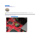
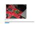
Back to Contents Page Coin-Cell Battery Dell™ OptiPlex™ 580 Service Manual—Mini Tower WARNING: Before working inside your computer, read the safety information that shipped with your computer. For additional safety best practices information, see the Regulatory Compliance Homepage at www.dell.com/regulatory_compliance. Removing the Coin-Cell Battery 1. 2. Follow the procedures in Before Working Inside Your Computer. Pull the retention clip away from the coin-cell battery. 3.
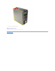
Replacing the Coin-Cell Battery To replace the coin-cell battery, perform the above steps in reverse order.
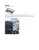
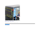
Back to Contents Page Cover Dell™ OptiPlex™ 580 Service Manual—Mini Tower WARNING: Before working inside your computer, read the safety information that shipped with your computer. For additional safety best practices information, see the Regulatory Compliance Homepage at www.dell.com/regulatory_compliance. Removing the Cover 1. 2. Follow the procedures in Before Working Inside Your Computer. Pull back the cover release latch. 3. Tilt the cover from the top outward.
4. Remove the cover from the computer. Replacing the Cover To replace the cover, perform the above steps in reverse order.
Back to Contents Page Diagnostics Dell™ OptiPlex™ 580 Service Manual—Mini Tower Dell Diagnostics Power Button Light Codes Beep Codes Diagnostic Lights Dell Diagnostics When to Use the Dell Diagnostics It is recommended that you print these procedures before you begin. NOTE: The Dell Diagnostics software works only on Dell computers. NOTE: The Drivers and Utilities media is optional and may not ship with your computer.
2. If a problem is encountered during a test, a message appears with an error code and a description of the problem. Write down the error code and problem description and follow the instructions on the screen. 3. If you run a test from the Custom Test or Symptom Tree option, click the applicable tab described in the following table for more information. Tab Function Results Displays the results of the test and any error conditions encountered.
The diagnostic lights are not lit after the computer successfully boots to the operating system. A possible processor failure has occurred. l Memory modules are detected, but a memory failure has occurred. l l l l A possible graphics card failure has occurred. l l l A possible floppy drive or hard drive failure has occurred. Reseat the processor (see Processor information for your computer). If the problem persists, contact Dell.
Back to Contents Page Drive Bezel Dell™ OptiPlex™ 580 Service Manual—Mini Tower WARNING: Before working inside your computer, read the safety information that shipped with your computer. For additional safety best practices information, see the Regulatory Compliance Homepage at www.dell.com/regulatory_compliance. Removing the Drive Bezel 1. 2. Follow the procedures in Before Working Inside Your Computer. Slide the drive-release latch toward the base of the computer. 3.
Replacing the Drive Bezel To replace the drive bezel, perform the above steps in reverse order.
Back to Contents Page Hard Drive Dell™ OptiPlex™ 580 Service Manual—Mini Tower WARNING: Before working inside your computer, read the safety information that shipped with your computer. For additional safety best practices information, see the Regulatory Compliance Homepage at www.dell.com/regulatory_compliance. Removing the Hard Drive 1. 2. Follow the procedures in Before Working Inside Your Computer. Disconnect the data cable from the hard drive. 4. Disconnect the power cable from the hard drive.
5. Press the blue release tabs on each side of the hard drive and slide the hard drive from the computer. Replacing the Hard Drive To replace the hard drive, perform the above steps in reverse order.
Back to Contents Page Heat Sink Dell™ OptiPlex™ 580 Service Manual–Mini-Tower WARNING: Before working inside your computer, read the safety information that shipped with your computer. For additional safety best practices information, see the Regulatory Compliance Homepage at www.dell.com/regulatory_compliance. Removing the Heat Sink 1. Follow the procedures in Before Working Inside Your Computer. 2. Loosen the captive screws that secure the heat sink to the system board. 3.
Replacing the Heat Sink To replace the heat sink, perform the above steps in reverse order.
Back to Contents Page I/O Panel Dell™ OptiPlex™ 580 Service Manual—Mini Tower WARNING: Before working inside your computer, read the safety information that shipped with your computer. For additional safety best practices information, see the Regulatory Compliance Homepage at www.dell.com/regulatory_compliance. Removing the I/O Panel 1. 2. Follow the procedures in Before Working Inside Your Computer. Disconnect the I/O panel data cable from the system board. 3.
4. Remove the screw that secures the I/O panel to the front of the computer. 5. Press the retention latch to release the I/O panel from the chassis.
6. Tilt the I/O panel toward the back of the computer. 7. Lift the I/O panel out of the slot and lay it on the drive cage.
8. Disconnect the data cable from the I/O panel. 9. Remove the I/O panel from the computer.
Replacing the I/O Panel To replace the I/O panel, perform the above steps in reverse order.
Back to Contents Page Memory Dell™ OptiPlex™ 580 Service Manual—Mini Tower WARNING: Before working inside your computer, read the safety information that shipped with your computer. For additional safety best practices information, see the Regulatory Compliance Homepage at www.dell.com/regulatory_compliance. Removing a Memory Module 1. 2. Follow the procedures in Before Working Inside Your Computer. Push down the memory retention clips to release the memory module. 3.
Replacing a Memory Module To replace a memory module, perform the above steps in reverse order.
Back to Contents Page Optical Drive Dell™ OptiPlex™ 580 Service Manual—Mini Tower WARNING: Before working inside your computer, read the safety information that shipped with your computer. For additional safety best practices information, see the Regulatory Compliance Homepage at www.dell.com/regulatory_compliance. Removing the Optical Drive NOTE: You may need to install Adobe Flash Player from Adobe.com to view the following illustrations. 1. 2. 3.
5. Slide the optical drive from the computer. Replacing the Optical Drive To replace the optical drive, perform the above steps in reverse order.
Back to Contents Page Removing and Replacing Parts Dell™ OptiPlex™ 580 Service Manual—Mini Tower Cover Drive Bezel Coin-Cell Battery Memory Optical Drive Fan Video Card I/O Panel Hard Drive Heat Sink Power Supply Processor System Board Back to Contents Page
Back to Contents Page Power Supply Dell™ OptiPlex™ 580 Service Manual—Mini Tower WARNING: Before working inside your computer, read the safety information that shipped with your computer. For additional safety best practices information, see the Regulatory Compliance Homepage at www.dell.com/regulatory_compliance. Removing the Power Supply 1. 2. Follow the procedures in Before Working Inside Your Computer. Remove the screws that secure the power supply to the back of the computer. 3.
4. Disconnect the optical-drive power cable from the optical drive. 5. Disconnect the processor power cable from the system board.
6. Disconnect the main power cable from the system board. 7. Remove all data cables from the cable routing clip at the base of the power supply.
9. Press the release latch that secures the power supply to the chassis.
10. Slide the power supply toward the front of the computer and lift the power supply up and away from the computer. Replacing the Power Supply To replace the power supply, perform the above steps in reverse order.
Back to Contents Page Processor Dell™ OptiPlex™ 580 Service Manual—Mini Tower WARNING: Before working inside your computer, read the safety information that shipped with your computer. For additional safety best practices information, see the Regulatory Compliance Homepage at www.dell.com/regulatory_compliance. Removing the Processor 1. 2. Follow the procedures in Before Working Inside Your Computer. Pull the processor cover release lever down and out to release the processor cover. 3.
4. Remove the processor from its socket on the system board. CAUTION: When replacing the processor, do not touch any of the pins inside the socket or allow any objects to fall on the pins in the socket. Replacing the Processor To replace the processor, perform the above steps in reverse order.
Back to Contents Page System Setup Dell™ OptiPlex™ 580 Service Manual—Mini Tower Overview Entering System Setup System Setup Options Overview Use System Setup to: l Change the system configuration information after you add, change, or remove any hardware in your computer. l Set or change a user-selectable option such as the user password. l View the installed amount of memory or set the type of hard drive installed.
L2 Cache Displays the amount of processor Level 2 cache L3 Cache Displays the amount of processor Level 3 cache Installed Memory Indicates the amount of installed memory Memory Speed Indicates the frequency of installed memory Memory Technology Indicates the type of installed memory SATA 0 Displays the SATA drives connected to the SATA 0 connector SATA 1 Displays the SATA drives connected to the SATA 1 connector SATA 2 Displays the SATA drives connected to the SATA 2 connector SATA 3 Displa
l TPM Security Enables or disables the TPM security feature. l l TPM Activation Off On Off (default) Activates or deactivates the TPM feature if it is enabled. l l l Enable Disable Don't Change Power AC Recovery Specifies the behavior of the system when AC power is restored after an AC power loss. l l l Auto Power On Enables the Auto Power On feature l l Remote Wake Up l Disabled Enabled (default) Allows the system to conserve power while in hibernate mode.
Provides options to Save Changes and Exit, Discard Changes and Exit, and Load Default Setting Back to Contents Page
Back to Contents Page Specifications Dell™ OptiPlex™ 580 Service Manual—Mini Tower Processor Controls and Lights Memory Network Expansion Bus Audio Video Power System Information System Board Connectors Cards Physical Drives Environmental External Connectors NOTE: Offerings may vary by region. For more information regarding the configuration of your computer, click Start® Help and Support and select the option to view information about your computer.
SATA 1.5 Gbps and 3.0 Gbps USB 480 Mbps (high speed) 12 Mbps (full speed) 1.2 Mbps (low speed) Cards PCI: Mini–tower two Desktop one low profile card Small form factor N/A PCI Express x4 one PCI Express x16 one NOTE: The PCI Express x16 slot is disabled when a display is connected to the integrated video connector. Drives Externally accessible: 5.25 inch drive bay(s): Mini-tower two Desktop one Small form factor one (slimline) Internally accessible: 3.
Serial ATA: Mini–tower four 7-pin connectors Desktop three 7-pin connectors Small form factor three 7-pin connectors Memory four 240-pin connectors Internal USB device none Processor fan one 5–pin connector Hard-drive fan: Mini–tower none Desktop none Small form factor one 5–pin connector Front panel control one 40–pin connector Processor AM3 941–pin connector Power 12V one 4–pin connector Power one 24–pin connector PS/2 or serial connector (optional) one 24–pin connector Control
NOTE: Heat dissipation is calculated by using the power supply wattage rating. NOTE: See the safety information that shipped with your computer for important voltage setting information. Physical Height: Mini–tower 40.80 cm (16.10 inches) Desktop 11.40 cm (4.50 inches) Small form factor 9.30 cm (3.70 inches) Width: Mini–tower 18.70 cm (7.40 inches) Desktop 39.90 cm (15.70 inches) Small form factor 31.40 cm (12.40 inches) Depth: Mini–tower 43.30 cm (17.00 inches) Desktop 35.30 cm (13.
Back to Contents Page System Board Layout Dell™ OptiPlex™ 580 Service Manual—Mini Tower 1 fan connector (FAN_CPU) 2 speaker connector (INT_SPKR) 3 processor connector (CPU) 4 processor power connector (12VPOWER) 5 memory module connectors (DIMM_1, DIMM_2, DIMM_3, and DIMM_4) 6 SATA connectors (SATA0 and SATA1) 7 front panel connector (FRONTPANEL) 8 power connector (POWER) 9 SATA connector (SATA2) 10 SATA connector (SATA3) 11 intrusion switch connector (INTRUDER) 12 coin-cell battery
Back to Contents Page System Board Dell™ OptiPlex™ 580 Service Manual—Mini Tower WARNING: Before working inside your computer, read the safety information that shipped with your computer. For additional safety best practices information, see the Regulatory Compliance Homepage at www.dell.com/regulatory_compliance. Removing the System Board 1. 2. 3. 4. 5. Follow the procedures in Before Working Inside Your Computer. Remove the memory. Remove the video card. Remove the heat sink.
7. Disconnect the system board power cable. 8. Disconnect the optical-drive data cable from the system board.
9. 10. Disconnect the hard-drive data cable from the system board. Disconnect the I/O-panel data cable from the system board.
11. Remove the screws that secure the heat sink assembly bracket to the system board. 12. Remove the heat sink assembly bracket from the computer.
13. Remove the screws that secure the system board to the chassis. 14. Remove the system board from the chassis.
Replacing the System Board To replace the system board, perform the above steps in reverse order.
Back to Contents Page Fan Dell™ OptiPlex™ 580 Service Manual—Mini Tower WARNING: Before working inside your computer, read the safety information that shipped with your computer. For additional safety best practices information, see the Regulatory Compliance Homepage at www.dell.com/regulatory_compliance. Removing the Fan 1. 2. Follow the procedures in Before Working Inside Your Computer. Disconnect the hard-drive power cable from the hard drive. 3. Disconnect the data cable from the hard drive.
4. Disconnect the fan power cable from the system board. 5. Pull up the retention tab that is closest to the top of the computer.
6. Press the fan retention tab that is closest to the base of the computer. 7. Slide the fan toward the back of the computer.
8. Remove the fan from the computer. Replacing the Fan To replace the fan, perform the above steps in reverse order.
Back to Contents Page Video Card Dell™ OptiPlex™ 580 Service Manual—Mini Tower WARNING: Before working inside your computer, read the safety information that shipped with your computer. For additional safety best practices information, see the Regulatory Compliance Homepage at www.dell.com/regulatory_compliance. Removing the Video Card 1. 2. Follow the procedures in Before Working Inside Your Computer. Press the release tab on the card retention latch from inside, then pivot the latch open. 3.
4. Lift the expansion card up and out of the expansion slot. Replacing the Video Card To replace the video card, perform the above steps in reverse order.
Back to Contents Page Working on Your Computer Dell™ OptiPlex™ 580 Service Manual—Mini Tower Before Working Inside Your Computer Recommended Tools Turning Off Your Computer After Working Inside Your Computer Before Working Inside Your Computer Use the following safety guidelines to help protect your computer from potential damage and to help to ensure your personal safety.
Click Start® Turn Off Computer® Turn Off. The computer turns off after the operating system shutdown process is complete. 2. Ensure that the computer and all attached devices are turned off. If your computer and attached devices did not automatically turn off when you shut down your operating system, press and hold the power button for about 6 seconds to turn them off.