
Owners Manual


c) Remove the two screws (M3x5) securing the I/O board shield to the display assembly base [3].
d) Lift the I/O board shield from the display assembly base [4].
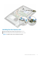
4. To remove the I/O board:
a) Remove the headset port cable from the routing guide on the I/O board [1].
b) Remove the two screws (M3x5) that secure the I/O board to the display assembly base [2].
c) Lift the I/O board with its cables from the display assembly base [3].
76
Removing and Installing components