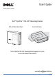
User’s Guide dell.com/regulatory_compliance Dell™ OptiPlex™ 780-USFF Mounting Bracket Wall with Wood Stud Mount Under Desk Mount The Dell OptiPlex 780-USFF Mounting Bracket supports the System in vertical or horizontal orientations. www.dell.com support.dell.
Hazard Symbols Review These symbols alert the user about a safety condition that demands attention. All users of the product should be able to recognize and understand the significance of the following safety hazards if encountered on the product or within product documentation. Symbol Signal Word Level of Hazard NOTE A NOTE indicates important information that helps you make better use of your Dell Mounting Bracket.
Contents 1 About your Dell OptiPlex 780-USFF Mounting Bracket ...................................................4 2 Setting up your Dell OptiPlex 780-USFF Mounting Bracket.............................................4 3 Specifications ............................................................................................................... 14 4 Finding Information .....................................................................................................
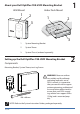
1 About your Dell OptiPlex 780-USFF Mounting Bracket Wall Mount 1 Under Desk Mount 2 1 2 3 3 1 System Mounting Bracket 2 System Sleeve 3 System Chassis (ordered separately) Setting up the Dell OptiPlex 780-USFF Mounting Bracket Components 2 Mounting Bracket, System Sleeve, two Lag Screws 2x M8 x 80 mm WARNING: Because surfaces vary widely and the ultimate mounting method is out of DELL’s control, it is imperative that you consult with an appropriate engineering, architectural or construct
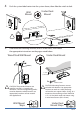
1 Ensure the system sleeve is unlocked, (orange tab will show). 2 Extend the system label carrier.
3 Insert the system into the system sleeve in the orientation appropriate to the mounting method as illustrated below. CAUTION: Do not reverse the insertion order. The system must be inserted in the orientation specified to ensure proper functioning of the CD tray! Wood Stud Wall Mount Insert the system into the system sleeve with the connections end first. NOTE: When inserted properly for wall mount applications, the connections end of the system will not reach the edge of the system sleeve.
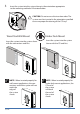
4 Push the system label carrier into the system sleeve, then slide the switch to lock. Under Desk Mount Wall Mount 5 Determine the mounting method (Wall or Under Desk), then follow the appropriate instructions on the pages noted below. Under Desk Mount Wood Stud Wall Mount ≥ 1/2” (1.25 cm) 4x CAUTION: The provided fasteners are rated for use with 2 x 4 wood studs, minimum. Consult an engineering professional to determine which fasteners are appropriate based on surface material and applied load.
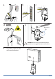
Wood Stud Wall Mount Steps 6 Stud Finder Attach the mounting bracket to the wood stud. NOTE: The following tools are required for installation to the wall stud: stud finder, measuring tape, pencil, level, safety glasses, power drill with 3/16” (5mm bit suitable for wood). Wall Mount Clearance Front View 2 1 Ø 5 mm (3/16”) Ceiling ≥3.33” (85 mm) ≥2.45” (62.2 mm) ≥2.28” (58 mm) Left Wall Right Wall Wall Mount Clearance Back View Ceiling ≥6.0” (152.4 mm) ≥13” (330.2 mm) Right Wall 8 of 14 ≥8.
a b c Stud Finder d Ø 5 mm (3/16”) e M8 x 80 mm 2x CAUTION: Make sure the wall mount bracket is level, flush and snuggly fitted to the wall surface. f Lower the system onto the wall-mounted bracket.
To remove the system from the mounting bracket: a Push the quick release tab backward. b Lift the system upward until it is free of the bracket. a b Under Desk Mount Steps 6 Mark the mounting hole locations using the measurements provided on the next pages. NOTE: The following tools are required for installation to the desk: measuring tape, pencil, level.
Under Desk Clearance during assembly Wall / Desk ≥6.0” (152.4 mm) ≥6.0” (152.4 mm) Wall / Desk ≤4.25” (108 mm) ≤ .5” (12.7 mm) Edge of Desk Under Desk Clearance after assembly Wall / Desk ≥6.0” (152.4 mm) ≥6.0” (152.4 mm) ≤4.25” (108 mm) Wall / Desk ≤ .5” (12.
Under Desk Clearance CAUTION: The system should have at least 6” (152.4 mm) of clearance on all vented sides to permit the airflow required for proper ventilation. Restricting airflow can damage the equipment or cause overheating. Wall / Desk Wall / Desk ≥6.0” (152.4 mm) ≥6.0” (152.4 mm) ≤4.25” (108 mm) Edge of Desk a Mount the bracket underneath the desk. CAUTION: Mounting fasteners are not included with bracket.
To remove the system from the mounting bracket: a Push the quick release tab upward. b Slide the system toward the right until it is free of the bracket.
3 Specifications System Weight Capacity Dell System: OptiPlex 780-USFF ≤ 7 lbs (3.2 kg) Temperature Operating Storage Transportation 32°F to 95°F (0°C to 35°C ) -40°F to 149°F (-40°C to +69°C) -40°F to 149°F (-40°C to +69°C) Finding Information 4 If you need to: See: Find safety best practices information for your computer, review Warranty information, Terms and Conditions (U.S.