Dell OptiPlex 790 Ultra Small Form Factor Owner's Manual Regulatory Model D01U Regulatory Type D01U001
Notes, Cautions, and Warnings NOTE: A NOTE indicates important information that helps you make better use of your computer. CAUTION: A CAUTION indicates potential damage to hardware or loss of data if instructions are not followed. WARNING: A WARNING indicates a potential for property damage, personal injury, or death. Information in this publication is subject to change without notice. © 2011 Dell Inc. All rights reserved.
Contents Notes, Cautions, and Warnings..................................................................2 1 Working on Your Computer......................................................................7 Before Working Inside Your Computer.............................................................................7 Recommended Tools.........................................................................................................8 Turning Off Your Computer.............................................
Installing The Chassis Intrusion Switch..........................................................................22 8 Speaker......................................................................................................23 Removing the Internal Speaker.......................................................................................23 Installing The Internal Speaker.......................................................................................24 9 Heat Sink And Processor...............
16 Drive Cage...............................................................................................45 Removing the Drive Cage................................................................................................45 Installing The Drive Cage................................................................................................46 17 Wireless Module....................................................................................47 Removing the Wireless Module.....................
Working on Your Computer 1 Before Working Inside Your Computer Use the following safety guidelines to help protect your computer from potential damage and to help to ensure your personal safety. Unless otherwise noted, each procedure included in this document assumes that the following conditions exist: • • You have read the safety information that shipped with your computer. A component can be replaced or--if purchased separately--installed by performing the removal procedure in reverse order.
CAUTION: When you disconnect a cable, pull on its connector or on its pull-tab, not on the cable itself. Some cables have connectors with locking tabs; if you are disconnecting this type of cable, press in on the locking tabs before you disconnect the cable. As you pull connectors apart, keep them evenly aligned to avoid bending any connector pins. Also, before you connect a cable, ensure that both connectors are correctly oriented and aligned.
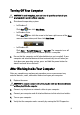
Turning Off Your Computer CAUTION: To avoid losing data, save and close all open files and exit all open programs before you turn off your computer. 1. Shut down the operating system: • In Windows 7: • Click Start , then click Shut Down. In Windows Vista: Click Start , then click the arrow in the lower-right corner of the Start menu as shown below, and then click Shut Down. • 2. In Windows XP: Click Start → Turn Off Computer → Turn Off .
Cover 2 Removing the Cover 1. Follow the procedures in Before Working Inside Your Computer. 2. Loosen the thumb screw that secures the computer cover. 3. Slide the cover towards the back of the computer. 4. Lift the cover up and away from the computer.
Installing The Cover 1. 2. 3. 4. 12 Place the computer cover on the chassis. Slide the computer cover towards the front of the chassis, until it clicks into place. Tighten the thumb screw to secure the computer cover. Follow the procedures in After Working Inside Your Computer.
Front Bezel 3 Removing the Front Bezel 1. Follow the procedures in Before Working Inside Your Computer. 2. 3. Remove the cover. Pry the front bezel retention clips away from the chassis. 4. Rotate the bezel away from the computer, to release the hooks on the opposite edge of the bezel from the chassis.
Installing The Front Bezel 1. 3. Insert the hooks along the bottom edge of the front bezel into the slots on the chassis front. Rotate the bezel toward the computer to engage the front bezel retention clips, until they click into place. Install the cover. 4. Follow the procedures in After Working Inside Your Computer. 2.
Optical Drive 4 Removing the Optical Drive 1. Follow the procedures in Before Working Inside Your Computer. 2. Remove the cover. 3. Remove the front bezel. 4. Remove the drive cage. 5. Release the retention clip and remove the optical drive from its cage. 6. Remove the optical drive bracket.
Installing The Optical Drive 1. 2. 3. Fix the optical drive bracket to the optical drive. Secure the optical drive into its cage. Install the drive cage. 4. 5. 6. Install the front bezel. Install the cover. Follow the procedures in After Working Inside Your Computer.
Hard Drive 5 Removing the Hard Drive 1. Follow the procedures in Before Working Inside Your Computer. 2. Remove the cover. 3. Remove the front bezel. 4. Remove the drive cage. 5. Remove the hard-drive cage from the compartment. 6. Remove the screws that secure the hard drive to the drive cage. 7. Slide the hard drive to release it from the drive cage.
Installing the Hard Drive 1. 2. 3. Slide the hard drive back into the drive cage. Tighten the screws to secure the hard drive to the drive cage. Install the drive cage. 4. 5. 6. Install the front bezel. Install the cover. Follow the procedures in After Working Inside Your Computer.
Memory 6 Removing the Memory 1. Follow the procedures in Before Working Inside Your Computer. 2. Remove the cover. 3. Remove the front bezel. 4. Remove the drive cage. 5. Press out on the release tabs located on each side of the memory module. 6. Lift the memory module out of the connector on the system board and remove it.
Installing The Memory 1. 2. 3. Insert the memory module into the connector on the system board. Press down on the memory module until the release tabs spring back to secure it in place. Install the drive cage. 4. 5. 6. Install the front bezel. Install the cover Follow the procedures in After Working Inside Your Computer.
Chassis Intrusion Switch 7 Removing the Chassis Intrusion Switch 1. Follow the procedures in Before Working Inside Your Computer. 2. Remove the cover. 3. Remove the front bezel. 4. Remove the drive cage. 5. Disconnect the intrusion cable from system board. 6. Slide the intrusion switch over and remove it off the bracket.
Installing The Chassis Intrusion Switch 1. 2. 3. Insert the intrusion switch into the bracket on the power supply and slide it over to secure it. Connect the intrusion cable to the system board. Install the drive cage. 4. 5. 6. Install the front bezel. Install the cover. Follow the procedures in After Working Inside Your Computer.
Speaker 8 Removing the Internal Speaker 1. Follow the procedures in Before Working Inside Your Computer. 2. Remove the cover. 3. Remove the front bezel. 4. Remove the drive cage. 5. Disconnect the speaker cable from the system board. 6. Pull out the speaker cable from beneath the system fan cable and wireless local Area network (WLAN) antennae (if installed).
7. Release the latch and rotate the speaker. 8. Remove the speaker from the chassis. Installing The Internal Speaker 1. Place the speaker on the appropriate location of the chassis rear and rotate until the latch is secured in place. 2. Route the speaker cable beneath the system fan cable and wireless local area network (WLAN) antennae (if installed). 3. Connect the speaker cable to the system board. 4. Install the drive cage. 5. Install the front bezel. 6. Install the cover. 7.
Heat Sink And Processor 9 Removing the Heat Sink 1. Follow the procedures in Before Working Inside Your Computer. 2. Remove the cover. 3. Remove the front bezel. 4. Remove the drive cage. 5. Disconnect the heat sink/fan assembly cable from the system board. 6. Press the release lever down and move it outward to release the fan retention hook that secures it.
7. Raise the heat sink/fan assembly. 8. Loosen the captive screws to secure the heat sink/fan assembly to the system board. 9. Lift the heat sink/fan assembly upward, and remove it from the computer. Lay the assembly with the fan facing downward, and with the thermal grease facing upward.
Installing The Heat Sink 1. 2. 5. 6. Place the heat sink/fan assembly into the chassis. Tighten the captive screws to secure the heat sink/fan assembly to the system board. Lower the heat sink/fan assembly. Press the release lever down and then move it inward to secure it with the fan retention hook. Connect the heat sink/fan assembly cable to the system board. Install the drive cage. 7. 8. 9. Install the front bezel. Install the cover. Follow the procedures in After Working Inside Your Computer. 3. 4.
Processor 10 Removing the Processor 1. Follow the procedures in Before Working Inside Your Computer. 2. 3. 4. 5. 6. Remove the cover. Remove the front bezel. Remove the drive cage. Remove the heat sink. Press the release lever down. Then move it outward to release it from the retention hook that secures it. 7. Raise the processor cover.
8. Lift the processor to remove it from the socket and place it into an antistatic packaging. Installing The Processor 1. Insert the processor into the processor socket. Ensure the processor is properly seated. 2. Lower the processor cover. 3. Press the release lever down and then move it inward to secure it with the retention hook. 4. Install the heat sink. 5. Install the drive cage. 6. Install the front bezel. 7. Install the cover. 8.
Coin-Cell Battery 11 Removing the Coin-Cell Battery 1. Follow the procedures in Before Working Inside Your Computer. 2. 3. 4. 5. 6. Remove the cover. Remove the front bezel. Remove the drive cage. Remove the heat sink. Press the release latch away from the battery to allow the battery to pop up from the socket. 7. Lift the coin-cell battery out of the computer and properly dispose of the battery.
Installing The Coin-Cell Battery 1. 2. 3. 4. 5. 6. 7. 32 Place the coin-cell battery into the slot on the system board. Press the coin-cell battery downward until the release latch springs back into place to secure it. Install the heat sink. Install the drive cage. Install the front bezel. Install the cover. Follow the procedures in After Working Inside Your Computer.
System Fan 12 Removing the System Fan 1. Follow the procedures in Before Working Inside Your Computer. 2. Remove the cover. 3. Remove the front bezel. 4. Remove the drive cage. 5. Disconnect the system-fan cable from the system board. 6. Disengage the system-fan cable from the chassis. 7. Remove the screws that secure the fan to the chassis.
8. Lift and remove the system fan out of the chassis. Installing The System Fan 1. 2. 3. 4. 5. 6. 7. 8. 34 Place the system fan in the chassis. Tighten the screws to secure the system fan to the chassis. Thread the system-fan cable into the chassis clip. Connect the system-fan cable to the system board. Install the drive cage. Install the front bezel. Install the cover. Follow the procedures in After Working Inside Your Computer.
Input/Output Panel 13 Removing the Input/Output Board 1. Follow the procedures in Before Working Inside Your Computer. 2. Remove the cover. 3. Remove the front bezel. 4. Remove the drive cage. 5. Disconnect the Input/Output board cable from the system board. 6. Remove the screws that secure the Input/Output bracket. 7. Remove the Input/Output bracket from the chassis.
8. Remove the screws that secure the Input/Output board. 9. Remove the Input/Output bracket. Installing the Input/Output Board 1. Align the Input/Output board with the Input/Output bracket and tighten the screws securing the Input/Output board. 2. Insert the Input/Output bracket into the slot on the chassis front. 3. Tighten the screws to secure the Input/Output bracket. 4. Connect the Input/Output board data cable to the system board. 5. Install the drive cage. 6. Install the front bezel.
Power Supply 14 Removing the Power Supply 1. Follow the procedures in Before Working Inside Your Computer. 2. 3. 4. 5. 6. 7. Remove the cover. Remove the front bezel. Remove the drive cage. Remove the intrusion switch. Remove the heat sink. Disconnect the cables from the system board. 8. Remove the screw that secures the power supply to the chassis.
9. Remove the screws that secure the power supply to the chassis. 10. Slide the power supply inward and remove the power supply. Installing The Power Supply 1. Place the power supply in the chassis and slide it outward to secure it. 2. Tighten screws to secure the power supply to the chassis. 3. Connect the cables to the system board. 4. Install the heat sink.
5. Install the intrusion switch. 6. 7. 8. 9. Install the drive cage. Install the front bezel. Install the cover. Follow the procedures in After Working Inside Your Computer.
System Board 15 Removing the System Board 1. Follow the procedures in Before Working Inside Your Computer. 2. Remove the cover. 3. Remove the front bezel. 4. Remove the drive cage. 5. Remove the power supply. 6. Remove the heat sink. 7. Remove the memory. 8. Remove the input/output panel. 9. Remove the wireless module. 10. Remove the speaker. 11. Disconnect all the cables connected to the system board, and move the cables away from the chassis. 12.
13. Remove the screws that secure the system board to the chassis. 14. Remove the 7–mm hex screw from the system board. 15. Slide the system board towards the front of the computer.
16. Remove the system board from the chassis. Installing The System Board 1. Align the system board to the port connectors on the rear of the chassis, and place the system board in the chassis. 2. Tighten the 7–mm hex screw to secure the system board to the chassis. 3. Tighten the screws to secure the system board to the chassis. 4. Thread the internal antenna into the chassis clips. 5.
12. Install the drive cage. 13. Install the front bezel. 14. Install the cover. 15. Follow the procedures in After Working Inside Your Computer.
Drive Cage 16 Removing the Drive Cage 1. Follow the procedures in Before Working Inside Your Computer. 2. Remove the cover. 3. Remove the front bezel. 4. Lift the drive cage using the handle and flip over the drive cage. 5. Remove the data cable and power cable from the back of the optical drive. 6. Remove the data cable and power cable from the back of the hard drive.
7. Remove the drive cage from the system. Installing The Drive Cage 1. 2. 3. 4. 5. 6. 7. 46 Place the drive cage on the edge of the computer to allow access to the cable connectors on the hard drive and optical drive. Connect the data cable and power cable to the back of the hard drive. Connect the data cable and power cable to the back of the optical drive. Flip over the drive cage and insert it into the chassis. The drive cage shoulder screws are secured by the slots in the chassis.
Wireless Module 17 Removing the Wireless Module 1. Follow the procedures in Before Working Inside Your Computer. 2. Remove the cover. 3. Remove the front bezel 4. Remove the drive cage. 5. Disconnect the cables from the wireless local area network (WLAN) card. 6. Push the securing levers away from the WLAN card. 7. Remove the WLAN card.
Installing The Wireless Module 1. 2. 3. 4. 5. 6. 7. 48 Slide the wireless local access network (WLAN) card into its slot. Press the WLAN card downward until it is locked in place by the securing levers. Connect the antennae according to the color code on the WLAN card. Install the drive cage. Install the front bezel. Install the cover. Follow the procedures in After Working Inside Your Computer.
Control Panel 18 Removing the Control Panel 1. Follow the procedures in Before Working Inside Your Computer. 2. Remove the cover. 3. Remove the front bezel. 4. Remove the drive cage. 5. Remove the memory. 6. Disconnect the control panel cable from the system board. 7. Unthread the control panel-speaker cable from the chassis clip.
8. Remove the screw that secures the control panel board. 9. Remove the control panel board. Installing The Control Panel 1. Insert the control panel board into the slot on the chassis front. 2. Tighten the screw to secure the control panel board. 3. Thread the control panel-speaker cable into the chassis clip. 4. Connect the control panel cable to the system board. 5. Install the memory. 6. Install the drive cage. 7. Install the front bezel. 8. Install the cover. 9.
Internal Antenna 19 Removing the Internal Antenna 1. Follow the procedures in Before Working Inside Your Computer. 2. Remove the cover. 3. Remove the front bezel. 4. Remove the drive cage. 5. Disconnect the cables from the wireless local area network (WLAN) card. 6. Unthread the internal antenna. 7. Release the internal antenna port.
8. Remove the internal antenna. Installing The Internal Antenna 1. 2. 3. 4. 5. 6. 7. 52 Insert the internal antenna into the port in the chassis and slide toward the right to secure it. Thread the internal antenna into the chassis clip. Connect the cables to the wireless local area network (WLAN) card. Install the drive cage. Install the front bezel. Install the cover. Follow the procedures in After Working Inside Your Computer.
System Setup 20 System Setup This computer offers you the following options: • • Access System Setup by pressing Bring up a one-time boot menu by pressing Press to enter System Setup and make changes to the user-definable settings. If you have trouble entering System Setup using this key, press when the keyboard LEDs first flash.
Partition. The benefit here is that you do not have to remember the and keystrokes (although they still work). NOTE: The BIOS features an option to disable either or both of the keystroke prompts under the System Security / Post Hotkeys submenu. When you enter the or keystroke correctly, the computer beeps. The key sequence invokes the Boot Device Menu.
Navigation The computer setup can be navigated by either the keyboard or the mouse.
General Boot Sequence Allows you to specify the order in which the computer attempts to find an operating system. The options are: • • • • • • Diskette drive USB Storage Device CD/DVD/CD-RW Drive Onboard NIC SATA CD/DVD/CD-RW Drive Boot List Option • • Legacy UEFI Date/Time Allows you to set the date and time. Changes to the system date and time take effect immediately. System Configuration Integrated NIC Allows you to enable or disable the integrated network card.
System Configuration NOTE: The operating system may allocate resources even though the setting is disabled. SATA Operation Allows you to configure the operating mode of the integrated hard drive controller.
Video Multi-Display Allows you to enable or disable Multi-Display. It should be enabled for Windows 7 32/64-bit only. . Enable Multi-Display — This option is disabled by default. NOTE: The Video setting will only be visible when a video card is installed in the system. Security Internal HDD-1 Password Allows you to set, change, or delete the password on the system's internal hard disk drive (HDD). Successful changes to this password take effect immediately.
Security Password Change Allows you to determine whether changes to the System and Hard Disk passwords are permitted when an administrator password is set. Allow Non-Admin Password Changes — This option is enabled by default. Non-Admin Setup Changes This option lets you determine whether changes to the setup option are permitted when an administrator password is set. Allow Wireless Switch Changes — This option is disabled by default.
Security these settings are capable of preventing access to Intel RAID (CTRL+I) or Intel Management Engine BIOS Extension (CTRL +P/F12) • • • Enable — User may enter OROM configuration screens via the hotkey. One-Time Enable — User may enter OROM configuration screens via the hotkeys on next boot only. After next boot, the setting will revert to disabled. Disable — User may not enter OROM configuration screens via the hotkey. This option is set to Enable by default.
Power Management AC Recovery Determines how the system responds when AC power is reapplied after a power loss. You can set the AC Recovery to: • • • Auto On Time Power Off (default) Power On Last State Allows you to set the option to automatically turn on the computer. Time is kept in standard 12-hour format (hour:minutes:seconds). Change the startup time by typing the values in the time and AM/PM fields.
POST Behavior Numlock LED Allows you to enable or disable the Numlock feature when your computer starts. This option is enabled by default. Keyboard Errors Allows you to enable or disable the keyboard error reporting when the computer starts. This option is enabled by default. POST Hotkeys Allows you to specify the function keys to display on the screen when the computer starts.
Maintenance SERR Messages Controls the SERR message mechanism. This option is not set by default. Some graphics cards require that the SERR message mechanism be disabled. Image Server Lookup Method Specifies how the ImageServer looks up the server address. • • Static IP DNS (enabled by default) NOTE: This field is only relevant when the "Integrated NIC" control in the "System Configuration" group is set to "Enabled with ImageServer".
Image Server NOTE: This field is only relevant when the "Integrated NIC" control in the "System Configuration" group is set to "Enabled with ImageServer" and when "Client DHCP" is set to "Static IP". Client Subnet Mask Specifies the subnet mask of the client. The default setting is 255.255.255.255. NOTE: This field is only relevant when the "Integrated NIC" control in the "System Configuration" group is set to "Enabled with ImageServer" and when "Client DHCP" is set to "Static IP".
Troubleshooting 21 Diagnostic LEDs NOTE: The diagnostic LEDs only serve as an indicator of the progress through the Power-on Self-Test (POST) process. These LEDs do not indicate the problem that caused the POST routine to stop. The diagnostic LEDs are located on the front of the chassis next to the power button. These diagnostic LEDs are only active and visible during the POST process. Once the operating system starts to load, they turn off and are no longer visible.
• • • Ensure that any power strips being used are plugged into an electrical outlet and are turned on. Ensure that the electrical outlet is working by testing it with another device, such as a lamp. Ensure that the main power cable and front panel cable are securely connected to the system board. LED Power Button Problem Description A possible system board failure has occurred. Troubleshooting Steps Unplug the computer. Allow one minute for the power to drain.
• If the LED still does not illuminate, the problem is with the power supply. LED Power Button Problem Description Memory modules are detected, but a memory power failure has occurred. Troubleshooting Steps • • If two or more memory modules are installed, remove the modules, then re-install one module and re-start the computer.
Problem Description A possible system board failure has occurred. Troubleshooting Steps Remove all peripheral cards from the PCI and PCI-E slots and re-start the computer. If the computer boots, add the peripheral cards back one by one until you find the bad one. LED Power Button Problem Description Power connector not installed properly. Troubleshooting Steps Re-seat the 2x2 power connector from the power supply unit.
• If the problem persists, the system board is faulty. LED Power Button Problem Description A possible coin cell battery failure has occurred. Troubleshooting Steps Remove the coin cell battery for one minute, reinstall the battery, and restart. LED Power Button Problem Description A possible processor failure has occurred. Troubleshooting Steps Re-seat the processor. LED Power Button Problem Description Memory modules are detected, but a memory failure has occurred.
• If available, install working memory of the same type into your computer. LED Power Button Problem Description A possible hard drive failure has occurred. Troubleshooting Steps Re-seat all power and data cables. LED Power Button Problem Description A possible USB failure has occurred. Troubleshooting Steps Re-install all USB devices and check all cable connections. LED Power Button Problem Description No memory modules are detected.
LED Power Button Problem Description Memory modules are detected, but a memory configuration or compatibility error has occurred. Troubleshooting Steps • • Ensure that no special requirements for memory module/connector placement exist. Ensure that the memory you are using is supported by your computer. LED Power Button Problem Description A possible expansion card failure has occurred.
Problem Description A possible system board resource and/or hardware failure has occurred. Troubleshooting Steps • • • Clear CMOS. Disconnect all internal and external peripherals, and restart the computer. If the computer boots, add the peripheral cards back one by one until you find the bad one. If the problem persists, the system board / system board component is faulty. LED Power Button Problem Description Some other failure has occurred.
Code 1-1-2 Cause Microprocessor register failure Code 1-1-3 Cause NVRAM Code 1-1-4 Cause ROM BIOS checksum failure Code 1-2-1 Cause Programmable interval timer Code 1-2-2 Cause DMA initialization failure Code 1-2-3 Cause DMA page register read/write failure Code 1-3-1 through 2-4-4 Cause DIMMs not being properly identified or used Code 3-1-1 Cause Slave DMA register failure Code 3-1-2 Cause Master DMA register failure Code 3-1-3 Cause Master interrupt mask register fai
Code 3-2-4 Cause Keyboard Controller Test failure Code 3-3-1 Cause NVRAM power loss Code 3-3-2 Cause NVRAM configuration Code 3-3-4 Cause Video Memory Test failure Code 3-4-1 Cause Screen initialization failure Code 3-4-2 Cause Screen retrace failure Code 3-4-3 Cause Search for video ROM failure Code 4–2–1 Cause No time tick Code 4–2–2 Cause Shutdown failure Code 4–2–3 Cause Gate A20 failure Code 4–2–4 Cause Unexpected interrupt in protected mode Code 4–3–1 Caus
Code 4–3–3 Cause Timer-chip counter 2 failure Code 4–3–4 Cause Time-of-day clock stopped Code 4–4–1 Cause Serial or parallel port test failure Code 4–4–2 Cause Failure to decompress code to shadowed memory Code 4–4–3 Cause Math coprocessor test failure Code 4–4–4 Cause Cache test failure Error Messages Address mark not found Description The BIOS found a faulty disk sector or could not find a particular disk sector.
Alert! Security override Jumper is installed. Description The MFG_MODE jumper has been set and AMT Management features are disabled until it is removed. Attachment failed to respond Description The floppy or hard drive controller cannot send data to the associated drive. Bad command or file name Description Ensure that you have spelled the command correctly, put spaces in the proper place, and used the correct pathname.
Decreasing available memory Description One or more memory modules may be faulty or improperly seated. Reinstall the memory modules and, if necessary, replace them. Diskette drive 0 seek failure Description A cable may be loose or the computer configuration information may not match the hardware configuration. Diskette read failure Description The floppy disk may be defective or a cable may be loose. If the drive access light turns on, try a different disk.
Hard-disk drive controller failure Description The hard drive failed initialization. Hard-disk drive failure Description The hard drive failed initialization. Hard-disk drive read failure Description The hard drive failed initialization. Invalid configuration information-please run SETUP program Description The computer configuration information does not match the hardware configuration. Invalid Memory configuration, please populate DIMM1 Description DIMM1 slot does not recognize a memory module.
Memory allocation error Description The software you are attempting to run is conflicting with the operating system, another program, or a utility. Memory data line failure at address, read value expecting value Description A memory module may be faulty or improperly seated. Reinstall the memory modules and, if necessary, replace them. Memory double word logic failure at address, read value expecting value Description A memory module may be faulty or improperly seated.
Memory tests terminated by keystroke Description A keystroke interrupted the memory test. No boot device available Description The computer cannot find the floppy disk or hard drive. No boot sector on hard-disk drive Description The computer configuration information in System Setup may be incorrect. No timer tick interrupt Description A chip on the system board might be malfunctioning.
Read fault Description The operating system cannot read from the floppy or hard drive, the computer could not find a particular sector on the disk, or the requested sector is defective. Requested sector not found Description The operating system cannot read from the floppy or hard drive, the computer could not find a particular sector on the disk, or the requested sector is defective. Reset failed Description The disk re-set operation failed.
Time-of-day not set-please run the System Setup program Description The time or date stored in System Setup does not match the computer clock. Timer chip counter 2 failed Description A chip on the system board may be malfunctioning. Unexpected interrupt in protected mode Description The keyboard controller may be malfunctioning or a memory module may be loose.
Write fault on selected drive Description The operating system cannot write to the floppy or hard drive. X:\ is not accessible. The device is not ready Description The floppy drive cannot read the disk. Insert a floppy disk into the drive and try again.
22 Specifications Technical Specifications NOTE: Offerings may vary by region. For more information regarding the configuration of your computer, click Start (or Start in Windows XP) Help and Support, and then select the option to view information about your computer.
Memory Desktop, Mini-Tower, Small Form Factor four DIMM slots Ultra Small Form Factor two DIMM slots Capacity 1 GB, 2 GB, and 4 GB Minimum Memory 1 GB Maximum memory Desktop, Mini-Tower, Small Form Factor 16 GB Ultra Small Form Factor 8 GB Video Integrated • • Discrete PCI Express x16 graphics adapter Video memory up to 1.
Expansion Bus • • x1-slot bidirectional speed – 500 MB/s x16-slot bidirectional speed – 16 GB/s SATA: 1.5 Gbps, 3.0 Gbps, and 6.
Drives Ultra Small Form Factor one slim line bay Internally Accessible: 3.5–inch SATA drive bays Mini-Tower two Desktop one Small Form Factor one Ultra Small Form Factor none 2.
External Connectors Back Panel: 5 Video 15-pin VGA connector, 20-pin DisplayPort connector NOTE: Available video connectors may vary based on the graphics card selected. System Board Connectors PCI 2.
System Board Connectors Mini-Tower, Desktop, Small Form Factor four 240-pin connectors Ultra Small Form Factor two 240-pin connectors Internal USB Mini-Tower, Desktop one 10-pin connector Small Form Factor, Ultra Small Form Factor none System Fan one 5-pin connector Front panel control Mini-Tower, Desktop, Small Form Factor one 34-pin connector Ultra Small Form Factor one 20-pin connector Desktop, Small Form Factor, Ultra Small Form Factor two 2-pin connectors Processor one 1155-pin connect
Controls and Lights Blinking amber light indicates a problem with the system board. Drive activity light Blue light — Blinking blue light indicates that the computer is reading data from or writing data to the hard drive. Diagnostic lights Four lights located on the front panel of the computer. Back of the computer: Link integrity light on integrated network adapter Green — a good 10 Mbps connection exists between the network and the computer.
Power Wattage Maximum Heat Dissipation Voltage Mini-Tower 265 W 1390 BTU/hr 100 VAC to 240 VAC, 50 Hz to 60 Hz, 5.0 A Desktop 250 W 1312 BTU/hr 100 VAC to 240 VAC, 50 Hz to 60 Hz, 4.4 A Small Form Factor 240 W 1259 BTU/hr 100 VAC to 240 VAC, 50 Hz to 60 Hz, 3.6 A; 100 VAC to 240 VAC, 50 Hz to 60 Hz, 4.0 A Ultra Small Form Factor 200 W 758 BTU/hr 100 VAC to 240 VAC, 50 Hz to 60 Hz, 2.9 A NOTE: Heat dissipation is calculated by using the power supply wattage rating.
Environmental Maximum vibration: Operating 0.25 GRMS Storage 0.5 GRMS Maximum shock: Operating 40 G Storage 105 G Altitude: Operating –15.2 m to 3048 m (–50 ft to 10,000 ft) Storage –15.2 m to 10,668 m (–50 ft to 35,000 ft) Airborne contaminant level G1 or lower as defined by ANSI/ISAS71.
Contacting Dell 23 Contacting Dell NOTE: If you do not have an active Internet connection, you can find contact information on your purchase invoice, packing slip, bill, or Dell product catalog. Dell provides several online and telephone-based support and service options. Availability varies by country and product, and some services may not be available in your area. To contact Dell for sales, technical support, or customer service issues: 1. 2. 3. 4. Visit support.dell.com.