Implementing a Hard Real-Time Data Acquisition and Control System on Linux RTAI-LXRT F.M.Klomp - 0499684 DCT 2005.72 Traineeship report Coach: M.G.E. Schneiders Supervisor: M.J.G. v.d.
ii
Summary In the Dynamics and Control Technology group of the department of Mechanical Engineering, dSPACE is a common choice for rapid control prototyping in multiple analog in/output set-ups. For smaller set-ups, up to 2 analog in/outputs, the TUeDACS QAD or AQI systems are usually used. The biggest advantage of the latter is the direct interface with Matlab Simulink. This report describes how dSPACE can be replaced by a system alike the TUeDACS QAD and AQI.
iv SUMMARY
Contents Summary 1 iii Introduction 1 2 Implementation of soft- and hardware 2.1 Real-Time OS . . . . . . . . . . . . . . . . . . . 2.1.1 Soft and Hard Real-Time . . . . . . . . . 2.1.2 RTAI . . . . . . . . . . . . . . . . . . . . 2.1.3 RTAI-LXRT . . . . . . . . . . . . . . . . . 2.2 Software: explanation and installation . . . . . . 2.2.1 Operating System (OS) and Matlab . . . . 2.2.2 S-function board drivers . . . . . . . . . . 2.3 Getting started . . . . . . . . . . . . . . . . . . . 2.3.
CONTENTS vi E.4 RTAI Target Real Time Workshop . . . . . . . . . . . . . . . . . . . . . . . . . . . . . .
Chapter 1 Introduction A cost-efficient alternative for the widely used but expensive dSPACE systems has to be created. The Data Acquisition and Control System (DACS) in the "light-weight positioning" project is used as a carrier for this task. Within this project lies the scope of this traineeship. The DACS specifications for this project are taken as an example, but the use should not be limited to this project. The DACS is developed for rapid control prototyping of mechanical systems.
CHAPTER 1. INTRODUCTION 2 The third and last option is described in this report. Using I/O boards with onboard processors no extra interface and hardware is needed. The boards are plugged in the PCI Bus of any PC. Writing the drivers as S-functions2 and using a Real-Time target, Real-Time Simulink executables can be directly interfaced from Simulink and model parameters can be changed on-the-fly in the same model. The hardware is cheap and requires no additional PC as with the xPC concept.
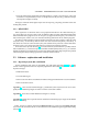
Chapter 2 Implementation of soft- and hardware 2.1 Real-Time OS 2.1.1 Soft and Hard Real-Time With an ordinary Linux kernel it is not possible to handle interrupts for user processes with highest performance. This implies that no Real-Time performance can be guaranteed. To make this possible two kernel extensions are available, Real-Time Application Interface (RTAI) and RTLinux. Both the extensions function in a similar way, with as important difference that RTAI is open-source freeware.
CHAPTER 2. IMPLEMENTATION OF SOFT- AND HARDWARE 4 • Since the RTOS and the application are linked together in a "single" execution space, system call mechanism is implemented by means of a simple function call (not using a software interrupt which produces higher overhead). Having less overhead makes higher sample rates for acquiring, computing controller actions and sending data possible. 2.1.3 RTAI-LXRT RTAI requires the use of kernel calls to access peripherical hardware in the Hard Real-Time process.
2.2. SOFTWARE: EXPLANATION AND INSTALLATION 5 2.2.2 S-function board drivers The source-code of the user space drivers and some kernel space routines for the two boards were supplied by the manufacturer [12]. This gave the opportunity to make a Real-Time driver which can interact with Simulink using LXRT. Simulink offers the possibility to use own c-code in the models by means of S-function [10] blocks. These S-function blocks are used as board drivers to initialize the boards and run the acquisition.
CHAPTER 2. IMPLEMENTATION OF SOFT- AND HARDWARE 6 The Acquisition Delay option in the AIn Simulink GUI has a big impact on the Ain driver function AiGetAIValue. First a command to acquire data is send to the PowerDAQ PD2-MF-16-500/16H board. The executable starts to evaluate the next command parallel to this. However the next command is reading the acquired data from the board, but the board is still acquiring. This results in bad readouts and/or sometimes even a shuffled channellist.
2.3. GETTING STARTED 7 ∗ The option -w makes a connection to the external mode of the Simulink model. – When -w is specified return to Simulink. ∗ ∗ ∗ ∗ Choose Simulation -> Connect To Target. Then Simulation -> Start Real-Time Code. Optionally adjust parameters while the model is executed. To stop the execution prematurely choose Simulation -> Stop Real-Time Code. 2.3.2 Simulink Graphical User Interface (GUI) In the file Total.mdl, which can be found in the 16AI_16AO_DACS.
CHAPTER 2. IMPLEMENTATION OF SOFT- AND HARDWARE 8 (a) GUI for Analog In. (b) GUI for Analog Out. Figure 2.2: GUI to set options for the Simulink blocks. • Board ID# This option should be set accordingly to the PCI slot position of the boards. The position can be checked with the command cat /proc/pwrdaq in the Konsole window. • Channel List Vector Can be specified in almost any way. channels can occur multiple times and are not fixed to a strict ascending or descending order.
Chapter 3 Performance of the DACS To give an idea of what the DACS is capable of, in this chapter the performance is evaluated by means of experiments. Before any experiment can begin, a Connector Box (CBox) has to be connected. The CBox has 16 coaxial female connectors for Analog In and 16 for Analog Out. They are all connected in single-ended mode to the PowerDAQ boards in the PC. To accommodate the experiments, the Analog In channels are connected to the Analog Out channels, see figure 3.1 Figure 3.
CHAPTER 3.
3.2. ACCURACY 11 With the Acquisition Delay set to 10000[ns], table 3.1 shows the maximal sample rates for three different sets of channels. This is without any controller, so only sending and acquiring data. As an example, the procedure above is carried out for a set of 7 AIn and 7 AOut channels. Only the desired set of channels is known, so first the maximal sample rate is determined to be 16[kHz] with an Acquisition Delay of 3000[ns]. N o of channels Sample rate [kHz] 1 22.5 8 15 16 9 Table 3.
12 CHAPTER 3. PERFORMANCE OF THE DACS 3.3 Discussion Once again it is stressed that the experiments described above are only mend to give a first impression. No hard conclusion can be drawn, merely some guesses of what to do to improve the performance and accuracy, because the DACS is not completely finished. Any change to the DACS will have an effect on the performance and accuracy. So a detailed survey is only useful after completion.
Chapter 4 Conclusions and Recommendations Conclusions Two Simulink S-function driver blocks for the PowerDAQ boards have been realized, which make Hard Real-Time execution of Simulink models possible on a Linux RTAI-LXRT platform. Together with the custom made Connector Box, a rapid control prototyping system is constructed. Using the standard user space library functions, the PowerDAQ PD2-AO-16/16 has a maximal sample rate of 100[kS/s] and the PowerDAQ PD2-MF-16-500/16H of 500[kS/s].
14 CHAPTER 4.
Appendix A S-function C-code A.1 Analog In file /* Analog input S-function for: United Electronic Industries PowerDAQ board type: PD2-MF-16-500/16H Input Fifo size: 1024 samples CL FIFO Size: 256 entries Output Fifo size: 2048 samples Mfg. date: 01-JAN-2003 Cal. date: 21-NOV-2003 Firmware type: MFx rev: 3.31/30819 (c) Frederik Klomp, Februari 2005 */ #define S_FUNCTION_NAME uei_pd2mf_ai #define S_FUNCTION_LEVEL 2 #include "simstruc.h" #include
APPENDIX A.
A.1.
18 #ifdef APPENDIX A. S-FUNCTION C-CODE MATLAB_MEX_FILE #include "simulink.c" #else #include "cg_sfun.
A.2. ANALOG OUT FILE 19 A.2 Analog Out file /* Analog output S-function for: United Electronic Industries PowerDAQ board type: PD2-AO-16/16 Output Fifo size: 2048 samples Mfg. date: 01-Oct-2003 Cal. date: 24-Nov-2003 Firmware type: AO rev: 3.31/30819 (c) Maurice Schneiders, September 2004 (c) Frederik Klomp, Februari 2005 */ #define S_FUNCTION_NAME uei_pd2ao_ao #define S_FUNCTION_LEVEL 2 #include "simstruc.h" #include
APPENDIX A.
A.2. ANALOG OUT FILE PdAcquireSubsystem(Handle, BoardLevel, 0); if (retVal < 0) { printf("AO: PdReleaseSubsystem error %d\n", retVal);} #endif } #ifdef MATLAB_MEX_FILE #include "simulink.c" #else #include "cg_sfun.
APPENDIX A.
Appendix B Listings of hardware and software Listing of hardware used: PC Dell OptiPlex GX270 R Pentium° R 4, 2.6 GHz CPU Intel° RAM 512 MB HD IDE, 19.5 GB Boards PowerDAQ board type: Analog In PD2-MF-16-500/16H Analog Out PD2-AO-16/16 monitor IIyama Vision Master 400 (horizontal sync range: 27-96 kHz, vertical sync range: 50-160 Hz) Listing of software used: Matlab version 6.1 R12 Real-Time Workshop version 4.0 Wintarget [4] for RTAI, using Matlab 6.1 RTAI version 3.0r3, using patched Linux kernel 2.4.
24 APPENDIX B.
Appendix C Installation of the Linux OS and extra software C.1 Linux OS The Knoppix 3.3 distribution is used, which can be installed from CD. Put the CD in the drive and wait for Knoppix to start. Next, start the konsole window and type knx-hdinstall, which will start the harddisk installation. Click through the options or use the extensive installation guide [3]. C.2 GCC 3.2 To be able to install version 3.2 of gcc (C-compiler), first a new apt-source has to be added to the system.
26 APPENDIX C. INSTALLATION OF THE LINUX OS AND EXTRA SOFTWARE Doing this, the listed are packages being updated and being installed. When asked, choose to restart services. While installing kdm you have to choose the standard “display manager”. Choose the option kmd. The new compilers gcc and g++ are not operational yet. First a symbolic link to the compiler has to be changed. Realize this with: cd /usr/bin ln -s -f gcc-3.2 gcc ln -s -f g++-3.
Appendix D Matlab 6.1 D.1 Preparation Before we can start installing Matlab 6.1, some settings in Debian need to be changed. First of all it has to be possible to start programs from CD. Open /etc/fstab in any text-editor. In the same line as /dev/cdrom add the option exec. /dev/cdrom /cdrom iso9660 ro,user,noauto,exec 0 0 It is now possible to mount a CD with the command mount /dev/cdrom.
APPENDIX D. MATLAB 6.1 28 • Simulink • Matlab Compiler • Real-time Workshop • FLEXm Check “Create symbolic links to Matlab and mex scripts” and choose /usr/local/bin as path. The display license number 0 is correct. D.3 Configuration After installation the FLEXm server should start automatically. This requires a startup script, which has to be copied: cp /usr/local/Matlab6p1/etc/rc.lm.glnx86 /etc/init.d/lm.glnx86 An option still needs to be changed in the startup script.
Appendix E RTAI In this appendix it is assumed you are logged in as root. You will need it at least for installing the kernel and RTAI. E.1 Requirements for RTAI The required software for RTAI can either be copied from the CD or be downloaded from internet. After copying the source-code onto the computer in any of the two ways it still needs to be unpacked. Downloading the software from the internet The kernel source-code can also be downloaded: http://www.kernel.
APPENDIX E. RTAI 30 – Set version information on all module symbols, choose N • Processor type and features – Processor family, choose Pentium-Pro/Celeron/Pentium-II – Real-Time Hardware Abstraction Layer, choose Y – Local APIC support on uniprocessor, choose Y • Networking options – Packet socket, choose Y (or else the DHCP will not work) – Socket filtering, choose Y (or else the DHCP will not work) • Network device support – Ethernet (10 or 100 Mbit) ∗ 3COM Cards, choose Y ∗ 3c590/3c900...
Bibliography [1] Linux COntrol and MEasurement Device Interface, "Comedi homepage", www.comedi.org. [2] dSPACE GmbH, "dSPACE homepage", www.dspace.com. [3] Knoppix 3.3 installation guide, kookboek.knoppix.nl/kk33hd.htm. [4] Dr. Ir. M.J.G. v.d. Molengraft is an assistant professor in the Control Systems Technology group of the Mechanical Engineering Department of Eindhoven University of Technology. TUeDACS support pages: http://www.tuedacs.nl/ or http://www.dct.tue.nl/home_of_wintarget.htm.