
Specifications


2.3. GETTING STARTED
7
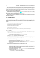
∗ The option -w makes a connection to the external mode of the Simulink model.
– When -w is specified return to Simulink.
∗ Choose Simulation -> Connect To Target.
∗ Then Simulation -> Start Real-Time Code.
∗ Optionally adjust parameters while the model is executed.
∗ To stop the execution prematurely choose Simulation -> Stop Real-Time Code.
2.3.2 Simulink Graphical User Interface (GUI)
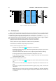
In the file Total.mdl, which can be found in the 16AI_16AO_DACS.zip archive, there is an
Analog In and Out block. The blocks contain the S-function device drivers and are shown in figure 3.2.
Used together with the two PowerDAQ boards and the custom made Connector Box in figure 3.1, up
to 16 channels Analog In and 16 channels Out can be read/send.
Predefined options for the boards When compared with the boards manuals the simulink blocks
lack a few options. For the sake of completeness this paragraph treats those options which have been
left out.
For the analog input PowerDAQ PD2-MF-16-500/16H board, which is used solely for acquiring data
1
,
these are:
• The input mode is chosen single ended. This is fixed in hardware through the connection
of the inputs in the data acquisition box.
• For clocking CL=software and CV=continuous are chosen. This combination for the
boards is typically used to acquire a single set of data points. This setting is recommended for
Real-Time control applications.
• For triggering the default option (software) is used.
• The data mode is set to fast, which is the default setting. Normal mode checks if a sample
is available to collect, this is safer but takes more time.
• The data format is fixed by the type of board and is 16 bit. for ours, see appendix B for
more information.
• The sampling method is also fixed by the board (sequential).
For the analog output board PowerDAQ PD2-AO-16/16, these are:
• The clock and trigger functionalities are combined in the update mode. There are 3 options;
this board is fixed to Single Update.
• data format is again fixed by the board (16 bit).
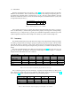
User defined options for the boards The options which can be set in the simulink environment are
listed below. Note that the Range in [V], Gain and SlowBit on/off options are the same for
all channels. The boards allow for setting these options for every channel separately. This slows down
the data acquisition considerably and is therefore left out.
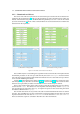
The options as seen in figure 2.2(a) for the PowerDAQ PD2-MF-16-500/16H board are:
1
This boards has two Analog outputs as well, but these are not supported by the S-function driver.