
Specifications


8
CHAPTER 2. IMPLEMENTATION OF SOFT- AND HARDWARE
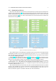
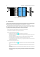
(a) GUI for Analog In. (b) GUI for Analog Out.
Figure 2.2: GUI to set options for the Simulink blocks.
• Board ID# This option should be set accordingly to the PCI slot position of the boards. The
position can be checked with the command cat /proc/pwrdaq in the Konsole window.
• Channel List Vector Can be specified in almost any way. channels can occur multiple
times and are not fixed to a strict ascending or descending order.
• Range in [V] There are 4 options to set the voltage range: [0 to 5], [0 to 10], [-5
to 5] and [-10 to 10].
• Gain Default set to 1, for more information see the PowerDAQ manual [7].
• Slow Bit on/off Can be set on or off. When set on, it gives leaves a larger time interval
between acquiring data for subsequent channels
• Acquisition Delay in [ns] Value for the time interval between the command to acquire
data and the command to read this data from the board. Adjusting this parameter is a compara-
tive assessment between lower achievable sample rates and incorrect acquisition.
And in figure 2.2(b) the options for the PowerDAQ PD2-AO-16/16 board are:
• Board ID# The same as for the Analog In board.
• Channel List Vector Also the same.