
Specifications


Chapter 3
Performance of the DACS
To give an idea of what the DACS is capable of, in this chapter the performance is evaluated by
means of experiments. Before any experiment can begin, a Connector Box (CBox) has to be connected.
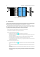
The CBox has 16 coaxial female connectors for Analog In and 16 for Analog Out. They are all con-
nected in single-ended mode to the PowerDAQ boards in the PC. To accommodate the experiments,
the Analog In channels are connected to the Analog Out channels, see figure 3.1
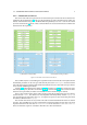
Figure 3.1: Custom made Connector Box for the PowerDAQ boards.
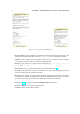
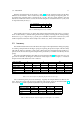
In Simulink the two S-function board driver blocks are put together in one model (figure 3.2). The
model can easily be adjusted to put a sine wave or a constant signal on the analog outputs. These
signals can be the same for all channels or can have a small amplitude difference. The analog input
values from the CBox inputs can be compared with the original signals. Both send and acquired data
is saved to the workspace for further calculations.
In the remaining sections, the performance and accuracy of the boards is treated. This is merely to
give an idea of what is working correctly and what to improve. Every set of channels can be optimized
for performance. For example if the model is executed on the same PC, logically a 1 AIn 1 AOut model
will achieve a far higher sample rate than a 16 AIn 16 AOut model.
When performing an experiment, an external oscilloscope should be used to verify if the model
executes Real-Time or not. For an unknown reason the target does not always correctly indicate missed
interrupts. With the scope this becomes apparent because a signal is transmitted for e.g. 3.5[s] instead
of the intended 3.0[s]. This problem should be resolved when newer versions of the software are
installed and is therefore ignored.
9