
Service Manual


Removing and Replacing Parts: Dell OptiPlex GX1 Systems Service Manual
file:///C|/infodev/2013/eDoc/OpGX1/SM/remsff.htm[2/21/2013 11:45:32 AM]
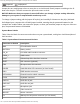
PANEL Control panel connector
PARALLEL Parallel port connector, sometimes referred to as LPT1
PCIn PCI expansion-card connector (on riser board)
POWER_1 Main power input connector
POWER_2 3.3-V power input connector
RISER Riser board connector
SERIALn Serial port connectors
SLOT1 Microprocessor connector
TAPI Telephony connector
USB USB connector
VIDEO_UPGRADE Video-memory upgrade socket
Expansion Cards
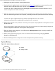
The small-form-factor GX1 chassis can accommodate up to two half-length 32-bit PCI expansion cards.
Figure 23 shows an example of a 32-bit PCI expansion card.
Figure 23. 32-Bit PCI Expansion Card Example
Removing an Expansion Card
CAUTION: Use a wrist grounding strap as explained in "Precautionary Measures."
To remove an expansion card, perform the following steps:
1. Remove the computer cover
.
2. If necessary, disconnect any cables connected to the card.
3. Remove the expansion-card cage.