Dell™ OptiPlex™ SX260 Systems User's Guide Documentation for Your Computer Finding Information for Your Computer Technical Specifications System Board Components Cleaning Your Computer Advanced Features LegacySelect Technology Control Manageability Security Password Protection System Setup Jumper Settings Power Button Hyper-Threading About Your Computer Front View Back View Back-Panel Connectors Inside Your Computer Orientations Chassis Stand Cable Cover Mounting Plate Connecting the Power Adapter Adding
Back to Contents Page Regulatory Notices Dell™ OptiPlex™ SX260 Systems User's Guide FCC Notices (U.S.
Once you have determined your system's FCC classification, read the appropriate FCC notice. Note that FCC regulations provide that changes or modifications not expressly approved by Dell could void your authority to operate this equipment. This device complies with Part 15 of the FCC Rules. Operation is subject to the following two conditions: l This device may not cause harmful interference. l This device must accept any interference received, including interference that may cause undesired operation.
CE Notice (European Union) Marking by the symbol indicates compliance of this Dell computer to the EMC Directive and the Low Voltage Directive of the European Union. Such marking is indicative that this Dell system meets the following technical standards: l EN 55022 — "Information Technology Equipment — Radio Disturbance Characteristics — Limits and Methods of Measurement." l EN 55024 — "Information Technology Equipment - Immunity Characteristics - Limits and Methods of Measurement.
Warning: This is a Class A product. In a domestic environment this product may cause radio interference, in which case the user may be required to take adequate measures. EN 55022 Compliance (Czech Republic Only) VCCI Notice (Japan Only) Most Dell computer systems are classified by the Voluntary Control Council for Interference (VCCI) as Class B information technology equipment (ITE). However, the inclusion of certain options can change the rating of some configurations to Class A.
Class B ITE This is a Class B product based on the standard of the Voluntary Control Council for Interference (VCCI) for information technology equipment. If this equipment is used near a radio or television receiver in a domestic environment, it may cause radio interference. Install and use the equipment according to the instruction manual.
If the regulatory label includes the following marking, your computer is a Class A product: Class B Device Please note that this device has been approved for nonbusiness purposes and may be used in any environment, including residential areas. MIC Class B Regulatory Label If the regulatory label includes the following marking, your computer is a Class B product.
BSMI Notice (Taiwan Only) If you find a or mark on the regulatory label on the bottom, side, or back panel of your computer, the following section is applicable:
NOM Information (Mexico Only) The following information is provided on the device(s) described in this document in compliance with the requirements of the official Mexican standards (NOM): Exporter: Dell Computer Corporation One Dell Way Round Rock, TX 78682 Importer: Dell Computer de México, S.A. de C.V. Paseo de la Reforma 2620 - 11° Piso Col. Lomas Altas 11950 México, D.F. Ship to: Dell Computer de México, S.A. de C.V. al Cuidado de Kuehne & Nagel de México S. de R.I. Avenida Soles No. 55 Col.
Back to Contents Page
Back to Contents Page Warranty and Return Policy Dell™ OptiPlex™ SX260 Systems User's Guide Dell Computer Corporation ("Dell") manufactures its hardware products from parts and components that are new or equivalent to new in accordance with industry-standard practices. For information about the Dell warranty for your computer, see the Setup and Quick Reference Guide.
Back to Contents Page About Your Computer Dell™ OptiPlex™ SX260 Systems User's Guide Front View Back View Back-Panel Connectors Inside Your Computer Orientations Chassis Stand Cable Cover Mounting Plate Connecting the Power Adapter Front View 1 power button Press this button to turn on the computer. NOTICE: To avoid losing data, do not use the power button to turn off the computer. Instead, perform a Microsoft® Windows® shutdown.
1 computer cover/hard- drive release button Press this button toward the cover release icon to remove the cover, or press this button toward the hard-drive icon to release the hard drive. 2 back-panel connectors The connectors for your computer. 3 power connector The connector for the power adapter. 4 diagnostic lights See "Diagnostic Lights" for a description of light codes that can help you troubleshoot problems with your computer.
CAUTION: Before you remove the computer cover, follow the steps in "CAUTION: Safety Instructions." CAUTION: To avoid electrical shock, always unplug your computer from the power adapter before removing the cover. CAUTION: To prevent static damage to components inside your computer, discharge static electricity from your body before you touch any of your computer's electronic components. You can do so by touching an unpainted metal surface on the computer chassis.
NOTICE: To ensure proper ventilation, do not place your computer vertically on a desktop without using the chassis stand (see "Chassis Stand"). NOTICE: To ensure proper ventilation, do not block the cooling vents. As an option, you may mount the computer to a vertical or horizontal surface by using a wall-mount bracket. If you have the integrated flat-panel option, the stand is integrated as part of the total assembly. Chassis Stand You may attach the chassis stand to orient your computer vertically.
Cable Cover NOTICE: If you are installing the computer under a desktop or tabletop, do not attach the cable cover until the computer is firmly attached to the mounting plate (see "Mounting Plate"). Attaching the Cable Cover NOTE: If you use the stand on your computer, attach the stand before attaching the cable cover.
1. Attach all the cables to the back panel. 2. To attach the two-piece cable cover, hold the bottom piece of the cable cover and align the four tabs with the four slots on the computer's back panel. 3. Insert the tabs into the slots and slide the piece toward the diagnostic lights (see the illustration) until it is securely positioned. 4. Grasp the top piece of the cable cover and align the two tabs with the two slots in the computer's back panel. 5.
NOTE: Before attaching the mounting plate to a surface, first orient yourself with how the stand will attach to the mounting plate. 1 release lever tab 2 mounting plate slot 3 screw holes (4) 4 solid surface with a 1-inch (2.5 cm) minimum thickness CAUTION: Attach the mounting plate to a solid surface capable of supporting 40 lbs (18.1 kg) hanging weight. 1. Using the four #6 wood screws (0.625 inch; 15.
1 mounting plate slot 2 release lever tab CAUTION: To avoid personal injury, remove the mounting plate if you are permanently removing the computer. 1. Firmly hold the computer and press on the release lever tab until the tab is freed from the slot on the mounting plate. 2. While still firmly holding the computer, slide the computer and stand approximately 1 inch (2.5 cm), until it stops. 3. Lower the computer and stand away from the mounting plate. Connecting the Power Adapter 1. 2.
3. Connect the metal ground connector to the grounding source on the outlet (see the following figure): a. Loosen the grounding source. b. Slide the metal ground connector behind the grounding source, and then tighten the grounding source. 1 grounding source 2 metal ground connector 4. Connect the power cable to the outlet.
Back to Contents Page Advanced Troubleshooting Dell™ OptiPlex™ SX260 Systems User's Guide Diagnostic Lights Beep Codes Dell Diagnostics Reinstalling Drivers Reinstalling Microsoft Windows XP Reinstalling Microsoft Windows 2000 Resolving Software and Hardware Incompatibilities Diagnostic Lights To help troubleshoot a problem, your computer has four lights on the back panel labeled "A","B","C," and "D." These lights can be either yellow or green.
green Possible video card failure or bad yellow on-board video green yellow If you have a video card, reseat it and restart the computer to retest. If you have video integrated, you must replace the system board. yellow Possible floppy or hard drive failure green green yellow Reseat all power and data cables, and restart the computer to retest. green Possible USB failure green green yellow Reseat all USB devices and cables, and restart the computer to retest.
1-3 Video Memory Test failure Run the VESA/VGA Interface tests in the Dell Diagnostics. DIMMs not being properly identified or used See "Memory Problems." 3-1-1 Slave DMA register failure Run the System Board Devices tests in the Dell Diagnostics, if possible. 3-1-2 Master DMA register failure Run the System Board Devices tests in the Dell Diagnostics, if possible. 3-1-3 Master interrupt mask register failure Contact Dell for technical assistance.
Enter system setup, review your computer's configuration information, and ensure that the device you want to test displays in system setup and is active. Start the Dell Diagnostics from either your hard drive or from the Drivers and Utilities CD (also known as the ResourceCD). Starting the Dell Diagnostics From Your Hard Drive 1. Shut down and restart the computer. 2. When the DELL® logo appears, press immediately.
If you cannot resolve the error condition, contact Dell. 3. If you run a test from the Custom Test or Symptom Tree option, click the applicable tab described in the following table for more information. Tab Function Results Displays the results of the test and any error conditions encountered. Errors Displays error conditions encountered, error codes, and problem description. Help Describes the test and may indicate requirements for running the test.
NOTE: The Product Key is the bar code number on the sticker that is located on the external side cover of your computer. You may be prompted for the Product Key when using the Operating System CD under certain conditions. Reinstalling Windows XP To reinstall Windows XP, perform all the steps in the following sections in the order in which they are listed. The reinstallation process can take 1 to 2 hours to complete.
17. Click Finish to complete the setup, and remove the CD from the drive. 18. Reinstall the appropriate drivers using the ResourceCD. 19. Reinstall your virus protection software. Reinstalling Microsoft Windows 2000 NOTICE: The Operating System CD provides options for reinstalling Windows XP. The options can overwrite files and possibly affect programs installed on your hard drive. Therefore, do not reinstall Windows XP unless instructed to do so by a Dell technical support representative.
Conflicts are indicated by a yellow exclamation point (!) beside the conflicting device or a red X if the device has been disabled. 5. Double-click any conflicting device listed to bring up the Properties window to determine what needs to be reconfigured or removed from the Device Manager. Resolve these conflicts before checking specific devices. 6. Double-click the malfunctioning device type in the Device Manager list. 7. Double-click the icon for the specific device in the expanded list.
Back to Contents Page Advanced Features Dell™ OptiPlex™ SX260 Systems User's Guide LegacySelect Technology Control Manageability Security Password Protection System Setup Jumper Settings Power Button Hyper-Threading LegacySelect Technology Control LegacySelect technology control offers legacy-full, legacy-reduced, or legacy-free solutions based on common platforms, hard-drive images, and help desk procedures.
IT Assistant configures, manages, and monitors computers and other devices on a corporate network. IT Assistant manages assets, configurations, events (alerts), and security for computers equipped with industry-standard management software. It supports instrumentation that conforms to SNMP, DMI, and CIM industry standards. Dell OpenManage Client instrumentation, which is based on DMI and CIM, is available for your computer.
NOTE: Before you purchase an antitheft device, make sure that it works with the security cable slot on your computer. Antitheft devices usually include a segment of metal-stranded cable with an attached locking device and key. Dell recommends that you use a Kensington lock. The documentation that comes with the device contains instructions for installing it. Password Protection NOTICE: Although passwords provide security for the data on your computer, they are not foolproof.
6. Exit system setup. Password protection takes effect when you restart the computer. Typing Your System Password When you start or restart your computer, one of the following prompts appears on the screen. If Password Status is set to Unlocked: Type in the password and - press to leave password security enabled. - press to disable password security. Enter password: If Password Status is set to Locked: Type the password and press .
6. Exit system setup. Setup Password Option Settings l Enabled — does not allow assignment of setup passwords; users must enter a setup password to make changes to system setup l Not Enabled — allows assignment of setup passwords; password feature is enabled but no password is assigned Assigning a Setup Password The setup password can be the same as the system password. NOTE: If the two passwords are different, the setup password can be used as an alternate system password.
Disabling a Forgotten Password and Setting a New Password NOTICE: This process erases both the system and setup passwords. CAUTION: Before you remove the computer cover, see "CAUTION: Safety Instructions." 1. Remove the computer cover. CAUTION: To prevent static damage to components inside your computer, discharge static electricity from your body before you touch any of your computer's electronic components. You can do so by touching an unpainted metal surface on the computer chassis. 2.
2. When Press to Enter Setup appears in the upper-right corner of the screen, press immediately. If you wait too long and the Microsoft® Windows® logo appears, continue to wait until you see the Windows desktop. Then shut down your computer and try again. NOTE: To ensure an orderly computer shutdown, see the documentation that came with your operating system. System Setup Screens System setup screens display current configuration information for your computer.
the computer to the boot routine. Exits system setup and restarts the computer, implementing any changes you have made. Resets the selected option to the default. Boot Device Menu This feature provides access to boot options and diagnostic features for your system. To access the boot device menu: 1. Turn on or restart your computer. 2. When F12 = Boot Menu appears in the upper-right corner of the screen, press . 3.
System Setup Options To get additional information about any setup option, highlight the entry and press . AC Power Recovery — determines what happens when AC power is restored to the computer. l l l Off — Computer remains off when AC power is restored. On — Computer starts when AC power is restored. Last — Computer returns to the AC power state existing at the time that AC power was lost.
If the computer generates a drive error message the first time you boot your computer after you install an IDE drive, your drive may not work with the automatic drive-type detect feature. Press in any hard drive field to set the hard drive autoconfiguration feature. During POST the computer scans the IDE channels for supported devices and generates a summary message.
jumpered unjumpered Power Button NOTICE: To turn off your computer, perform an orderly computer shutdown when possible. You can use the ACPI feature to configure the function of the Microsoft Windows 2000, and Windows XP operating systems.
To determine if your computer is using Hyper-Threading technology: 1. Click the Start button, right-click My Computer, and then click Properties. 2. Click Hardware and click Device Manager. 3. In the Device Manager window, click the plus (+) sign next to the processor type. If Hyper-Threading is enabled, the processor is listed twice. You can enable or disable Hyper-Threading through system setup.
Back to Contents Page Battery Dell™ OptiPlex™ SX260 Systems User's Guide CAUTION: Before you begin this procedure, follow the steps in "CAUTION: Safety Instructions." CAUTION: To prevent static damage to components inside your computer, discharge static electricity from your body before you touch any of your computer's electronic components. You can do so by touching an unpainted metal surface on the computer chassis. A coin-cell battery maintains computer configuration, date, and time information.
1 location of the battery connector 6. Replace the computer cover. 7. Reattach the stand (if used). 8. Replace the cable cover (if used). NOTICE: To connect a network cable, first plug the cable into the network wall jack and then plug it into the computer. 9. Connect your computer to the adapter cable and devices to electrical outlets, and turn them on.
Back to Contents Page Cleaning Your Computer Dell™ OptiPlex™ SX260 Systems User's Guide Before Cleaning Your Computer Computer, Keyboard, and Monitor Mouse Floppy Drive CDs and DVDs Before Cleaning Your Computer CAUTION: Before you begin any of the procedures in this section, follow the steps in "CAUTION: Safety Instructions." 1. Perform an orderly computer shutdown using the operating system menu.
CDs and DVDs 1. Hold the disc by its outer edge. It is okay to touch the inside edge of the center hole. NOTICE: To prevent damaging the surface, do not wipe in a circular motion around the disc. 2. With a soft, lint-free cloth, gently wipe the bottom of the disc (the unlabeled side) in a straight line from the center to the outer edge of the disc. For stubborn dirt, try using water or a diluted solution of water and mild soap.
Back to Contents Page Module Bay Dell™ OptiPlex™ SX260 Systems User's Guide You can install a Dell™ portable device such as a floppy drive, CD drive, CD-RW drive, DVD drive, DVD/CD-RW drive, or second hard drive in the module bay. Your Dell computer ships with either a floppy drive or an airbay (filler blank) installed in the module bay. NOTICE: To prevent damage to devices, place them in a safe, dry place when they are not installed in the computer.
1 module bay 2 airbay 3 module eject button 3. Slide the device into the module bay. 4. If desired, you may lock the device in the module bay by moving the module locking switch to the locked position. 5. Replace the hard-drive door. To remove a floppy drive, follow steps 1 and 2 in the previous procedure. Installing a CD/DVD Device When Your Computer Is Running Microsoft Windows® XP To install a CD/DVD device or second hard drive: 1.
1 module locking switch 2 locked position 3 unlocked position 4. While pressing the module eject button, grasp the airbay and pull it out of the module bay. NOTICE: Do not place any heavy objects on top of the computer. Doing so may cause difficulty in removing a module device. 1 module bay 2 airbay 3 module eject button 5. Slide the device into the module bay. 6. If desired, you may lock the device in the module bay by moving the module locking switch to the locked position. 7.
Installing a CD/DVD Device When Your Computer Is Running Windows 2000 To install a CD/DVD device or second hard drive: 1. Click the Unplug or Eject Hardware icon on the taskbar. 2. Click the device you want to eject and click Stop. 3. If the module bay is locked, open the hard-drive door and move the module locking switch to the unlocked position. 1 module locking switch 2 locked position 3 unlocked position 4.
1 module bay 2 airbay 3 module eject button 5. Slide the device into the module bay. 6. If desired, you may lock the device in the module bay by moving the module locking switch to the locked position. 7. Replace the hard-drive door. 8. When the operating system recognizes the new device, click Close.
Back to Contents Page Replacing the Computer Cover Dell™ OptiPlex™ SX260 Systems User's Guide 1. Ensure that no tools or extra parts are left inside the computer. 2. Replace the cover: 1 a. Lower and align the cover with the two lines on the metal computer frame. a. Slide the cover until you hear or feel it click into place. alignment lines NOTICE: To connect a network cable, first plug the cable into the network wall jack, and then plug it into the computer. 3.
Back to Contents Page Removing the Computer Cover Dell™ OptiPlex™ SX260 Systems User's Guide CAUTION: Before you begin this procedure, follow the steps in "CAUTION: Safety Instructions." CAUTION: To prevent static damage to components inside your computer, discharge static electricity from your body before you touch any of your computer's electronic components. You can do so by touching an unpainted metal surface on the computer chassis. 1. 2. Shut down the computer through the Start menu.
Back to Contents Page Documentation for Your Computer Dell™ OptiPlex™ SX260 Systems User's Guide Finding Information for Your Computer Technical Specifications System Board Components Cleaning Your Computer Back to Contents Page
Back to Contents Page Ergonomic Computing Habits Dell™ OptiPlex™ SX260 Systems User's Guide CAUTION: Improper or prolonged keyboard use may result in injury. CAUTION: Viewing the monitor screen for extended periods of time may result in eye strain. For comfort and efficiency, observe the following ergonomic guidelines when setting up and using your computer workstation: l Position your computer so that the monitor and keyboard are directly in front of you as you work.
References: 1. American National Standards Institute. ANSI/HFES 100: American National Standards for Human Factors Engineering of Visual Display Terminal Workstations. Santa Monica, CA: Human Factors Society, Inc., 1988. 2. Human Factors and Ergonomics Society. BSR/HFES 100 Draft standard for trial use: Human Factors Engineering of Computer Workstations. Santa Monica, CA: Human Factors and Ergonomics Society, 2002. 3. International Organization for Standardization (ISO).
Back to Contents Page Finding Information for Your Computer Dell™ OptiPlex™ SX260 Systems User's Guide What Are You Looking For? l l l l A diagnostic program for my computer Drivers for my computer My computer documentation My device documentation Find It Here Drivers and Utilities CD (also known as the ResourceCD) You can use this CD to access documentation, reinstall drivers, or run diagnostics tools.
l settings How to troubleshoot and solve problems Depending on your operating system, double-click the User's Guides icon on your desktop or click the Start button and then click Help and Support to access the electronic documentation stored on your hard drive.
Back to Contents Page Getting Help Dell™ OptiPlex™ SX260 Systems User's Guide Technical Assistance Problems With Your Order Product Information Returning Items for Warranty Repair or Credit Before You Call Contacting Dell Technical Assistance If you need help with a technical problem, Dell is ready to assist you. NOTE: Remove all external security features (Kensington locks and cable cover) before you call technical support.
www.dell.com/la/ (for Latin American countries) l Anonymous file transfer protocol (FTP) ftp.dell.com/ Log in as user: anonymous, and use your e-mail address as your password. l Electronic Support Service mobile_support@us.dell.com support@us.dell.com apsupport@dell.com (for Asian/Pacific countries only) support.euro.dell.com (for Europe only) l Electronic Quote Service sales@dell.com apmarketing@dell.com (for Asian/Pacific countries only) l Electronic Information Service info@dell.
To contact Dell's technical support service, see "Technical Assistance" and then call the number for your country as listed in "Contacting Dell." Problems With Your Order If you have a problem with your order, such as missing parts, wrong parts, or incorrect billing, contact Dell for customer assistance. Have your invoice or packing slip handy when you call. For the telephone number to call, see the contact numbers for your region.
Return Material Authorization Number (if provided by Dell support technician): Operating system and version: Devices: Expansion cards: Are you connected to a network? Yes No Network, version, and network adapter: Programs and versions: See your operating system documentation to determine the contents of the system's start-up files. If the computer is connected to a printer, print each file. Otherwise, record the contents of each file before calling Dell.
Belgium (Brussels) International Access Code: 00 Country Code: 32 Website: support.euro.dell.com E-mail: tech_be@dell.com E-mail for French Speaking Customers: support.euro.dell.
Country Code: 420 Customer Care 02 22 83 27 11 City Code: 2 Fax 02 22 83 27 14 TechFax 02 22 83 27 28 Switchboard 02 22 83 27 11 Denmark (Copenhagen) International Access Code: 00 Website: support.euro.dell.com E-mail Support (portable computers): den_nbk_support@dell.com E-mail Support (desktop computers): den_support@dell.com Country Code: 45 E-mail Support (servers): Nordic_server_support@dell.
Country Code: 852 India Ireland (Cherrywood) International Access Code: 16 Transaction Sales toll-free: 800 96 4109 Large Corporate Accounts HK toll-free: 800 96 4108 Large Corporate Accounts GCP HK toll-free: 800 90 3708 Technical Support 1600 33 8045 Sales 1600 33 8044 Website: support.euro.dell.com E-mail: dell_direct_support@dell.com Ireland Technical Support Country Code: 353 U.K. Technical Support (dial within U.K.
SalesFax (Austin, Texas, U.S.A.) 512 728-4600 or 512 728-3772 Luxembourg International Access Code: 00 Website: support.euro.dell.com E-mail: tech_be@dell.
International Access Code: 00 Country Code: 47 E-mail Support (portable computers): nor_nbk_support@dell.com E-mail Support (desktop computers): nor_support@dell.com E-mail Support (servers): nordic_server_support@dell.com Technical Support 671 16882 Relational Customer Care 671 17514 Home/Small Business Customer Care Switchboard 23162298 671 16800 Fax Switchboard 671 16865 Panama General Support 001-800-507-0962 Peru General Support 0800-50-669 Poland (Warsaw) Website: support.euro.dell.
Sweden (Upplands Vasby) International Access Code: 00 Country Code: 46 Website: support.euro.dell.com E-mail: swe_support@dell.com E-mail Support for Latitude and Inspiron: Swe-nbk_kats@dell.com E-mail Support for OptiPlex: Swe_kats@dell.com City Code: 8 E-mail Support for Servers: Nordic_server_support@dell.
Financial Services website: www.dellfinancialservices.
Back to Contents Page Glossary Dell™ OptiPlex™ SX260 Systems User's Guide A B C D E F G H I K L M N O P R S T U V W X Z A AC — alternating current — The form of electricity that powers your computer when you plug the AC adapter power cable into an electrical outlet.
Clock speed — The speed, given in MHz, that indicates how fast computer components that are connected to the system bus operate. Components that are synchronized with the clock speed can run faster or slower, but their speed is determined by multiplying or dividing a factor by the clock speed. cm — centimeter — A metric unit of measure equal to 0.39 inch. COA — Certificate of Authenticity — The Windows alpha-numeric code located on a sticker on your computer.
Extended Display Mode — A display setting that allows you to use a second monitor as an extension of your display. Also referred to as dual display mode. Extended PC Card — A PC card that extends beyond the edge of the PC card slot when installed. F F — Fahrenheit — A temperature measurement system where 32° is the freezing point and 212° is the boiling point of water. FCC — Federal Communications Commission — A U.S.
ISP — Internet service provider — A company that allows you to access its host server to connect directly to the Internet. The ISP gives you a software package, user name, and access phone numbers for a monthly fee. If your computer has a modem, you can connect to the Internet, access websites, and send and receive e-mail. K Kb — kilobit — A unit of data that equals 1024 bytes. A measurement of the capacity of memory integrated circuits.
is used for maintaining computer configuration information such as date, time, and other system setup options that you can set. O On-Board — Usually refers to components that are physically located or integrated on the computer's system board. P Parallel connector — An I/O port often used to connect a parallel printer to your computer. Also referred to as an LPT port. Partition — A physical storage area on a hard drive that is assigned to one or more logical storage areas known as logical drives.
Service tag — A bar code label on your computer that identifies your computer when you access Dell | Support at support.dell.com or when you call Dell for customer or technical support. Setup program — A program that is used to install and configure hardware and software. The setup.exe or install.exe program comes with most Windows software packages. Setup program differs from system setup program. Shortcut — An icon that provides quick access to frequently used programs, files, folders, and drives.
WHr — watt-hour — A unit of measure commonly used to indicate the approximate capacity of a battery. For example, a 66 WHr battery can supply 66 W of power for 1 hour or 33 W for 2 hours. Wallpaper — The background pattern or picture on the Windows desktop. Change your wallpaper through the Windows Control Panel. You can also scan in your favorite picture and make it wallpaper. Write-Protected — Files or media that cannot be changed.
Back to Contents Page Hard Drive Dell™ OptiPlex™ SX260 Systems User's Guide CAUTION: Before you begin this procedure, follow the steps in "CAUTION: Safety Instructions." CAUTION: To guard against electrical shock, always unplug your computer from the power supply before removing the hard drive. CAUTION: To prevent static damage to components inside your computer, discharge static electricity from your body before you touch any of your computer's electronic components.
12. 13. If your replacement drive is not attached to a metal sled: a. While holding the drive that you are replacing, remove the screws that hold the drive to the sled. b. Attach the replacement drive to the sled and replace the screws as shown in the illustration. Slide the new drive onto the plastic door.
NOTICE: There are four extra pins on the hard drive that are not on the cable connector. Use care when attaching the cable so that the drive pins are not bent or broken. 14. Attach the drive cable to the connector on the new drive, being careful not to bend any of the pins. 1 drive cable 2 drive connector 15. Slide the drive into the drive bay and lower the hard-drive door to lock into place. 16. Replace the cable cover (if used). 17. Attach the computer to the mounting plate (if used).
NOTE: If a setup password has been assigned by someone else, contact your network administrator for information on resetting the chassis intrusion detector.
Back to Contents Page Memory Dell™ OptiPlex™ SX260 Systems User's Guide Removing a Memory Module Adding a Memory Module CAUTION: Before you begin this procedure, follow the steps in "CAUTION: Safety Instructions." CAUTION: To guard against electrical shock, always unplug your computer from the electrical outlet before opening the cover.
1 cutouts (2) 2 connector 3 memory module 4 notch 5 securing clips (2) 6 memory connectors on system board 2. Align the notch on the bottom of the module with the crossbar in the connector. NOTICE: To avoid damage to the memory module, press the module straight down into the socket with equal force applied at each end of the module. 3. Insert the module straight down into the connector, ensuring that it fits into the vertical guides at each end of the connector.
The computer should have changed the value of System Memory to reflect the newly installed memory. Verify the new total. If it is correct, skip to step 12. 11. If the memory total is incorrect, turn off and disconnect your computer from the power adapter and devices from their electrical outlets. Remove the computer cover and check the installed memory modules to ensure that they are seated properly in their sockets. Then repeat steps 4 through 9. 12.
Back to Contents Page Adding and Removing Parts Dell™ OptiPlex™ SX260 Systems User's Guide Removing the Computer Cover Battery Module Bay Hard Drive Memory Microprocessor Replacing the Computer Cover Back to Contents Page
Back to Contents Page Microprocessor Dell™ OptiPlex™ SX260 Systems User's Guide CAUTION: Before you begin this procedure, follow the steps in "CAUTION: Safety Instructions." CAUTION: To prevent static damage to components inside your computer, discharge static electricity from your body before you touch any of your computer's electronic components. You can do so by touching an unpainted metal surface on the computer chassis. 1. 2. Shut down the computer through the Start menu.
11. Remove the heat sink. a. 1 2 Remove the two securing brackets, if present, by pressing the tabs together and lifting the brackets up. tabs (2 on each securing bracket) securing brackets (2) NOTE: Your computer may or may not have securing brackets. Operating the computer without these brackets does not affect its performance. b. Remove the memory module (see "Removing a Memory Module") closest to the heat sink. c. Press the lever on the retention base until the heat sink is released.
NOTICE: Be careful not to bend any of the pins when you remove the microprocessor. Bending the pins can permanently damage the microprocessor. 12. Pull the release lever straight up until the microprocessor is released, and then remove the microprocessor from the socket. 1 release lever 2 microprocessor 3 socket NOTICE: Ground yourself by touching an unpainted metal surface on the back of the computer. NOTICE: Be careful not to bend any of the pins when you unpack the microprocessor.
16. Set the microprocessor lightly in the socket and ensure that all pins are headed into the correct holes. Do not use force, which could bend the pins if the microprocessor is misaligned. When the microprocessor is positioned correctly, press it with minimal pressure to seat it. 17. When the microprocessor is fully seated in the socket, pivot the release lever back toward the socket until it snaps into place to secure the microprocessor.
Back to Contents Page
Back to Contents Page CAUTION: Safety Instructions Dell™ OptiPlex™ SX260 Systems User's Guide General When Working Inside Your Computer Protecting Against Electrostatic Discharge Ergonomic Computing Habits Battery Disposal Use the following safety guidelines to help ensure your own personal safety and to help protect your computer and working environment from potential damage. General l l l l l l l l l l l l Do not attempt to service the computer yourself unless you are a trained service technician.
Doing so reduces the potential for personal injury or shock. In addition, take note of these safety guidelines when appropriate: l l When you disconnect a cable, pull on its connector or on its strain-relief loop, not on the cable itself. Some cables have a connector with locking tabs; if you are disconnecting this type of cable, press in on the locking tabs before disconnecting the cable. As you pull connectors apart, keep them evenly aligned to avoid bending any connector pins.
Back to Contents Page Solving Problems Dell™ OptiPlex™ SX260 Systems User's Guide System Lights Mouse Problems Battery Problems Network Problems Drive Problems Power Problems Repairing a Wet Computer Printer Problems Dropped or Damaged Computer Serial or Parallel Device Problems Error Messages Sound and Speaker Problems General Problems System Board Problems Keyboard Problems Video and Monitor Problems Memory Problems System Lights Located on the front of the computer, these lights can in
Drive Problems Fill out the Diagnostics Checklist as you complete these checks. Floppy drive problems Test the drive — l l Insert another disk to eliminate the possibility that the original floppy disk is defective. Insert a bootable floppy disk and reboot the computer. Ensure that the disk is not full or write-protected — Ensure that the disk has available space and that it is not write-protected (locked). See the following illustration.
Close other programs — The CD-RW drive must receive a steady stream of data when writing. If the stream is interrupted, an error occurs. Try closing all programs before writing to the CD-RW. DVD drive problems NOTE: Because of different worldwide file types, not all DVD titles work in all DVD drives. Test the drive with another DVD — Insert another DVD to eliminate the possibility that the original DVD is defective. Ensure that Windows recognizes the drive — Click the Start button and click My Computer.
2. 3. Let the computer dry for at least 24 hours. Make sure that it is thoroughly dry before you proceed. Replace the computer cover, reconnect the computer and devices to their electrical outlets, and turn them on. If the computer has power, proceed to the next step. If the computer does not have power, contact Dell. Run the System Board Devices test group in the Dell Diagnostics. If any of the diagnostics tests fail, contact Dell. 4.
Drive not ready — No floppy disk is in the drive. Put a floppy disk in the drive. Gate A20 failure — One or more memory modules might be faulty or improperly seated. l l Reinstall the memory modules (see "Memory") and, if necessary, replace them. See "Memory Problems" for additional troubleshooting suggestions. General failure — The operating system is unable to carry out the command. This message is usually followed by specific information—for example, Printer out of paper.
Requested sector not found — The operating system cannot read from the floppy or hard drive, the computer could not find a particular sector on the disk, or the requested sector is defective. See "Floppy drive problems" or "Hard drive problems" for troubleshooting suggestions. Reset failed — The disk reset operation failed. See "Floppy drive problems" or "Hard drive problems" for troubleshooting suggestions. Sector not found — The operating system cannot locate a sector on the floppy or hard drive.
A program crashes repeatedly NOTE: Software usually includes installation instructions in its documentation or on a floppy disk or CD. Check the software documentation — Many software manufacturers maintain websites with information that may help you solve the problem. Ensure that you properly installed and configured the program. If necessary, uninstall and then reinstall the program.
l The mouse pointer does not move or "stutters" when it moves. l Messages appear stating that the computer is not operating at maximum performance. l Errors occur and programs crash for no apparent reason. l Nothing displays on the monitor. Remove any recently added hardware to see if it resolves the conflict — If removing the hardware resolves the conflict, see the hardware documentation for configuration and troubleshooting instructions.
Fill out the Diagnostics Checklist as you complete these checks. Restart the computer — 1. 2. 3. Simultaneously press to display the Start menu. Type u, press the keyboard arrow keys to highlight Shut down or Turn Off, and then press . After the computer turns off, press the power button to restart the computer. Check the mouse cable — l l Check the cable connector for bent or broken pins and for damaged or frayed cables. Straighten bent pins.
l l l l l l l Reseat both ends of the power adapter and power cable. If the computer power adapter is plugged into a power strip, ensure that the power strip is plugged into an electrical outlet and that the power strip is turned on. Ensure that the electrical outlet is working by testing it with another device, such as a lamp. Bypass power protection devices, power strips, and power extension cables to verify that the computer turns on.
Fill out the Diagnostics Checklist as you complete these checks. NOTE: If you are having a problem with a printer, see "Printer Problems." Check the documentation for the device — See the device's documentation for troubleshooting procedures. Ensure that the device is turned on — Firmly press the device's power button. Check the device cable connections — Check the connector for bent or broken pins. (It is normal for most device cable connectors to have missing pins.
Disable digital mode — Your headphones do not work if the CD drive is operating in digital mode. To disable digital mode: 1. 2. 3. 4. 5. 6. Click the Start button, click Control Panel, and then click Sounds, Speech, and Audio Devices. Click Sounds and Audio Devices. Click the Hardware tab. Double-click the name of your CD drive. Click the Properties tab. Uncheck the Enable digital CD audio for this CD-ROM device box.
Check the monitor settings — See the monitor documentation for instructions on adjusting the contrast and brightness, demagnetizing (degaussing) the monitor, and running the monitor self-test. Move the subwoofer away from the monitor — If your speaker system includes a subwoofer, ensure that the subwoofer is at least 60 cm (2 ft) away from the monitor.
Back to Contents Page Technical Specifications Dell™ OptiPlex™ SX260 Systems User's Guide Microprocessor Ports Memory Key Combinations Computer Information Controls and Lights Audio Power Video Physical Expansion Bus Environmental Drives Microprocessor Microprocessor type Level 1 (L1) cache Level 2 (L2) cache Intel® Pentium® 4 and Celeron® microprocessors. Design provides for future processor upgrades. Supported processor upgrades are available from Dell. 8 KB 1.5–2.
Externally accessible: Serial (data terminal equipment [DTE]) one 9-pin connector; 16550-compatible on the back I/O panel Parallel one 25-hole connector (bidirectional) on the back I/O panel Video 15-hole VGA connector on the back I/O panel Integrated network adapter RJ45 connector on the back I/O panel; 10/100/1000 PS/2-style keyboard 6-pin mini-DIN on the back I/O panel PS/2-compatible mouse 6-pin mini-DIN on the back I/O panel USB four USB-compliant connectors on the back I/O panel; two on t
Relative humidity 20% to 80% (noncondensing) Maximum vibration: Operating Storage desktop or vertical hanging orientation: 0.25 gravities (G) at 3 to 200 Hz at 0.5 octave/min; horizontal orientation: 0.25 G at 20 to 200 Hz at 0.5 octave/min 0.5 G at 3 to 200 Hz at 1 octave/min Maximum shock: Operating bottom half-sine pulse with a change in velocity of 20 inches/sec (50.
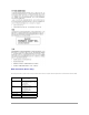
Back to Contents Page System Board Components Dell™ OptiPlex™ SX260 Systems User's Guide 1 fan shroud power connector (FAN2) 2 system board speaker (SPEAKER) 3 speaker connector (SPEAKER) 4 memory modules (DIMM_A and DIMM_B) 5 RTC reset jumper (RTCRST) 6 password jumper (PSWD) 7 standby power indicator (12V_PWR) 8 chassis intrusion switch power connector (INTRUDER) 9 battery (BATTERY) 10 fan shroud power connector (FAN1) 11 microprocessor heat sink Back to Contents Page
Back to Contents Page Microsoft® Windows® XP Features Dell™ OptiPlex™ SX260 Systems User's Guide Overview New User Interface Files and Settings Transfer Wizard Application and Device Compatibility System Restore User Accounts and Fast User Switching Home and Small Office Networking Internet Connection Firewall Overview Based on an enhanced version of the Windows 2000 operating system, Windows XP is available in consumer and business editions: Windows XP Home Edition and Windows XP Professional.
icons for accessing your files, configuring the computer, and finding information and assistance. The Dell Solution Center icon opens a portal to services and application programs installed on your Dell computer. Switching to Classic View If you want, you may change the appearance of the Start menu, desktop and windows, or Control Panel layout to that of earlier Windows operating systems. These classic view options are independent of each other.
Taskbar Grouping The Windows taskbar is a row of buttons that typically displays across the bottom of the screen. The taskbar includes the Start menu button and a button for each open application. (The taskbar also includes the Quick Launch icons and the notification area.) Windows XP groups multiple instances of the same application on the taskbar.
A program compatibility feature is provided in Windows XP that solves some issues that may be encountered when attempting to run older application programs. Using the Program Compatibility Wizard, you can configure a program to run in an environment closer to Windows 95, Windows 98/Me, Windows NT 4.0 with Service Pack 5, or Windows 2000. To use the Program Compatibility Wizard: 1. Click the Start button, point to All Programs—> Accessories, and click Program Compatibility Wizard. 2.
By default, System Restore creates a restore point every day that the computer is running. If your computer is off for more than a day, a new restore point is created the next time you turn the computer on. Event-Triggered Restore Points Event-triggered restore points are created before key changes are made to the system.
restoration. To undo a restoration: 1. Click the Start button, point to All Programs—> Accessories—> System Tools, and then click System Restore. 2. Select Undo my last restoration and click Next>. 3. Click Next> to confirm the restoration undo. After System Restore finishes collecting data, the computer automatically restarts and the Undo Complete screen appears. 4. Click OK. Driver Rollback Windows XP device Driver Rollback can replace a device driver with the previously installed version.
When a fast user switch occurs, the original user is not logged off the computer as previously happened on other Microsoft operating systems. On Windows XP, the user's logon remains active, but is replaced by the new user. Users can switch between login IDs as often as they want. However, user applications active during a user switch remain active and running in the background while the new user is working; this can result in a slower computer until the process finishes.
5. 6. Under Pick an account type, click the bullet next to the type of account you are going to create — Computer administrator, Standard, or Limited. l Computer administrators can change all computer settings. l Standard account users (Windows XP Professional only) can install some programs and hardware. l Limited account users can change only a few settings such as their own passwords. Click Create Account. After the accounts are created, each shows up on the Fast User Switching Welcome screen.
disabled. Additional configuration options are available for more advanced users. These advanced options include the ability to open or close specific Transmission Control Protocol (TCP) or User Datagram Protocol (UDP) ports or to enable port redirection. Port redirection allows access requests to a specific port on the firewall (such as port 80, the Web server port) to be automatically redirected to another computer on the local network.